Article

Hairpin Windings for Electric Vehicle Motors: Modeling and Investigation of AC Loss-Mitigating Approaches

by
Payam Shams Ghahfarokhi
1,2,3,*,
Andrejs Podgornovs
1,
Antonio J. Marques Cardoso
3,
Ants Kallaste
2,
Anouar Belahcen
4 and
Toomas Vaimann
2
1
Department of Electrical Machines and Apparatus, Riga Technical University, Kaļķu iela 1, LV-1048 Riga, Latvia
2
Department of Electrical Power Engineering and Mechatronics, Tallinn University of Technology, 19086 Tallinn, Estonia
3
CISE—Electromechatronic Systems Research Centre, University of Beira Interior, 6201-001 Covilhã, Portugal
4
Department of Electrical Engineering and Automation, Aalto University, P.O. Box 15500, 00076 Espoo, Finland
*
Author to whom correspondence should be addressed.
Machines 2022, 10(11), 1029; https://doi.org/10.3390/machines10111029
Submission received: 6 October 2022 / Revised: 31 October 2022 / Accepted: 2 November 2022 / Published: 4 November 2022

Abstract

:
The hairpin winding configuration has been attracting attention as a solution to increase the power density of electric vehicle motors by enhancing the slot-filling factor. However, this winding configuration brings high AC losses during high-speed operation and we require new approaches to tackle this challenge. This paper considers reducing AC losses by proposing two main methods: correct transposition of conductors in parallel paths, and enhancing the number of conductor layers in a slot. First, the proper connection of conductors in parallel paths is considered, and the essential rules for this purpose are described. Next, the paper uses a numerical approach to deal with the effect of incorrect conductor transposition in winding paths on generating additional AC losses due to circulating currents. Finally, the impact of the number of conductor layers in the mitigation of AC losses is also discussed in detail. According to the results, by increasing the number of layers, ohmic losses in the layer near the slot opening dramatically decrease. For instance, ohmic losses in the layer near the slot opening of the eight-layer setup were 82% less than the two-layer layout.

1. Introduction

Due to the destructive effects of combustion engines on global warming and the environment, there is an increased demand for sustainable and green transportation [1,2]. Therefore, due to intensive research and development in transportation electrification for all applications, hybrid and pure electric vehicles (EVs) have been proposed and developed [3,4]. The demanded metrics mainly concentrate on maximizing power and torque density and minimizing the weight of electric motors [5,6].
The requirement for maximizing the electric motors’ power and torque density has led to a revolution in winding technology [7]. The key enabler point is to find a way to increase the slot-filling factor. In earlier investigations, research studies mainly concentrated on increasing the traditional round-wound wire-filling factor by proposing an orthocyclic, layered winding methodology and the pressing tooth-wound [7]. However, none of the aforementioned methods achieved the desired result; the orthocyclic and layered winding methodology requires specific and expensive equipment and machinery types, and the pressing tooth-wound can only be implemented for electric motors with concentrated windings [7].
The practical option for maximizing electric motors’ power and torque density for traction applications and overcoming the drawbacks mentioned earlier is replacing the traditional round-wound wires with rectangular hairpins [1,8]. This winding configuration has various advantages over traditional round-wound winding, for instance, less complexity, a higher possibility of mass production, maximizing current density, shorter end winding, and lower DC copper losses [1,9]. More recently, hairpin windings technology has gained attention as the standard solution for high-reliability motor drives for hybrid electric vehicles [9,10,11]. As illustrated in Figure 1, this winding technology has been applied to hybrid electric vehicles such as the Toyota Prius and Chevrolet Volt /Bolt [8,12].
However, this solution leads to some drawbacks and challenges, for instance, low motor-design flexibility that arises from a fabrication perspective [1,8,9,11,13]. Furthermore, the traction motor for electric vehicle applications has a maximum speed of above 12000 rpm and depends on the number of poles; their fundamental frequency reaches more than 1 kHz. Due to the skin and proximity, the current density distribution inside the conductors is non-uniform. Therefore, these types of winding generate high AC losses [1,10,14,15]. Improvements to the hairpin design should be aimed at mitigating AC losses to enhance the reliability and the electric motors’ working speed limits for transportation electrification purposes.
The main objective of this paper is to investigate ways to mitigate AC losses. For this purpose, two different methods are investigated: the first relies on the correct transposition of rectangular conductors in parallel paths to reduce recirculating currents, and the second is based on increasing the number of conductor layers in slots to reduce the cross-section of each conductor, leading to a reduction in the impact of skin and proximity effects.

2. Basic Design Rules of Hairpin Winding and Case Study

The working voltage of traction motors has increased, and in some cases, it reaches about 800 V. Furthermore, these motors are implemented for high-current and -speed applications. Hence, the winding design with parallel paths is essential. In this situation, the conductors’ correct transposition into parallel paths is essential for eliminating potential circulating currents between parallel branches that generate additional AC losses. This section explains the fundamental design principle for hairpin windings and the proper transposition and connection of series conductors in the wire path. In addition, the effect of incorrect transposition of conductors in the wire path on additional AC losses is also considered.

2.1. Hairpin Winding Design Principle

Layout plots are an effective way to explain and provide an intuitive view of hairpin connections. For example, Figure 2a,b illustrate two conceivable ways of designing a three-phase, six-layer hairpin winding layout for a 36-slot, four-pole stator. The number of stator slots per phase (qm), and number of slots per pole per phase (q), are calculated as [16]:
    q m = N s m
q = N s 2 m p
where Ns is the number of stator slots, m is the number of phases, and p is the number of pole pairs.
According to Equation (1) and (2), the number of stator slots per phase is qm = 12, and the number of slots per pole per phase is q = 3. Figure 2a shows the connection of the winding layers (nw) with one parallel path per phase (Naa = 1), and the number of series turns per phase (Nst) is calculated as follows [16]:
N s t = 2 n w p q N a a
Therefore, in this specific design, the number of series turns per phase is Nst = 36. The winding connections start from layer a of slot 1 (S1-a), and during the first revolution (in each revolution, the number of turns is 2p), they continue to cover conductor layers a and b with full pitch. After completing the first revolution, S28-b is connected to S2-a using a jumper short pitch to change the phasor (slot). After finalizing the second revolution, another jumper changes the phasor and connects S29-b to S3-a. After completing the third revolution, another short-pitch jumper must change the layer level from a and b to c and d and connect S30-b to S1-c. This process continues for three successive revolutions to change the phasor, and after completing three multiple revolutions, the layer levels are changed, and finally, it is finished by going back to S30-a.
The hairpins count as lap-winding topology and follows these winding format connection rules [8]. According to the above hairpins layout, the principle rules for the number of stator slots and hairpin winding are as follows [8,17]:
  • The number of slots per pole pair must be greater than one to provide the possibility of generating electro-motive force (EMF);
  • The number of slots per phase per parallel path must be an integer;
  • The number of pole pairs per parallel path is equal to 2k, where k is an integer;
  • The number of slots per phase divided by the greatest common divisor of the number of slots, and the number of pole pairs (GCD (slots, pole pairs)) must be an integer;
  • The number of conductors in the slot must be even.
If the number of parallel paths per phase is greater than one (Naa > 1), the following two rules, titled transposition rules, are essential in a hairpin winding configuration:
  • Layer arrangement rules: In the presence of parallel paths, the wires belonging to one similar path should be placed in all layers of the slot to provide the same inductances for all parallel paths;
  • Slot per pole arrangement rule: To make sure that all parallel paths generate the same EMF, the wire that belongs to one similar path should be distributed in all slots per pole per phase.
Figure 2b illustrates the winding transposition for two parallel paths (Naa = 2): the paths are represented by black and red arrows. In this design, the number of series turns per phase is Nst = 18. Accordingly, one path starts from S01-a, and the other starts from S01-f. Correct driving transposition rules and the layer arrangement and number of slots per pole per phase rules are essential in this condition. To increase the resolution, conductors included in path one are displayed in orange, and those belonging to path two are displayed in blue. According to Figure 2b, each path’s wires located in all slot layers provide similar inductance, and all slots per pole of that phase contribute to balancing the EMF. The concept of winding transposition is critical in wires with parallel paths. Therefore, a 33 kW synchronous reluctance motor (SynRM) with a 36-slot, four-pole, with six-layer layout, 400 V, and a base speed of 4500 rpm was selected as a case study to check and validate the correct transposition (analytical winding configuration) of the 36-slot layout with two parallel paths presented in Figure 2b using Motor-CAD. When using the SynRM rotor, the investigation procedure is more straightforward as the impact of PM eddy current losses does not interfere when one is considering AC losses to check the performance of hairpin winding.
For this purpose, the SynRM for EV applications, with the parameters presented in Table 1, is defined in Motor-CAD. Furthermore, Motor-CAD provides the option titled custom in the winding pattern table. By selecting this option, the designer can manually implement a hairpin configuration and define the conductors’ transposition. Hence, as seen in Figure 3a, the winding transposition is defined as a table on the winding pattern page. In addition, the slot coil arrangement of phase one and linear hairpin winding patterns are shown in Figure 3b,c, respectively. Finally, Figure 3d shows the phasor diagram of the three phases of the SynRM. The three phases are displaced from each other by 120 degrees, and it can be concluded that the proposed winding pattern is correct.

2.2. Additional AC Losses

Failure to follow the transposing rules leads to a significant circulating current, thus increasing AC losses. A quarter of the SynRM is modeled to reduce computational burden using the finite element analysis (FEA) approach to investigate the effect of the incorrect transposition of rectangular conductors on additional AC losses. For this purpose, the 2D FE commercial software package Magnet from Mentor Graphics is used. Figure 4a shows the geometry of a quarter of the SynRM with the names and positions of phases and conductors. Figure 4b,c illustrate the proposed correct transposition and incorrect transposition equivalent circuits, respectively. These circuit models consist of each conductor’s details, which permit access to each conductor to find ohmic losses, including the summation of AC and DC copper losses. In the incorrect transposition circuit, the connection of conductors A3 (Slot A1-Conductor A3) and A4 (Slot A1-Conductor A4) is changed. Both models were solved using the time-harmonic approach for the frequency domain range from 1 Hz to 1 kHz.
Figure 5a,b show the FEA results of correct and incorrect winding transposing, respectively. The comparison of the FEA models, especially for A3 and A4 conductors, shows that the current density distribution in A3 and A4 is significantly changed. Moreover, Figure 5c shows the changing value of ohmic losses versus frequency for A3 and A4, for correct and incorrect models.
As seen in Figure 5c, the AC losses in A3 and A4 change dramatically. For instance, in the incorrect transposition model, the amount of ohmic loss of conductor A3 for the frequency of 1 kHz rises to about 88% more than its value for the correct format. In addition, ohmic loss behaviors for both conductors have entirely changed in the incorrect transposition model. For example, as seen in Figure 5c, for the incorrect case, ohmic losses for both conductors rise rapidly, while for the correct model, after a particular frequency, the intensity of the increment of ohmic losses decreases.

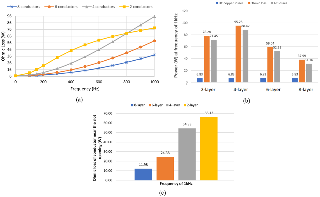
3. Number of Conductor Layers

The hairpin winding configuration has low motor-design flexibility and suffers from high AC losses. The high AC losses limit the motor’s operation speed (frequency). Therefore, it requires new winding techniques to mitigate AC losses of hairpins and enhance the motor’s operation speed (frequency). An effective way to mitigate AC losses is to increase the number of conductor layers in a slot. Thus, the conductor height and cross-section are reduced, and skin and proximity effects are reduced.
In conventional machine design, resistive losses of m-phase machines are computed as [18]:
P C u =   m R A C I 2
The AC resistance of one phase (RAC) is expressed as [19]:
R A C =   K A C η R D C
where KAC is a dimensionless coefficient, RDC is the winding DC resistance, and η is the characteristic height of the conductor given by (6) in the case of a rectangular conductor [19,20]:
η = ϵ l h c δ
where ϵl is the layer filling factor for a rectangular conductor, hc is conductor height, and δ is the skin depth.
According to (5), the challenging factor in AC winding resistance calculation is the dimensionless coefficient (KAC). Therefore, the layer conductor model is implemented to precisely determine the dimensionless coefficient (KAC) as follows [19,20]:
K A C = C I η + C I I η 1 + 2 1 l 1 N I N l I 0 2
where l is the number of the layer, N is the number of conductors, and CI(η) and CII(η) are defined as [19,20]:
C I η = η sinh η + sin η 2 cosh η cos η
C I I η = η sinh η sin η 2 cosh η + cos η
Therefore, correlations of AC loss factors for the various layers and an entire slot are defined, respectively, as follows [19]:
K A C l a y e r   n = C I η + C I I η 2 n 1 2
K A C = C I η + C I I η n i = 1 n 2 n 1 2
According to (6), (10), and (11), AC losses are a function of the conductor height and the number of conductor layers.
The numerical approach is used to further study the effect of the number of layers on AC copper losses in the hairpin winding configuration. Since AC losses chiefly pertain to leakage flux in the slot, a single slot is modeled using the software to reduce the computational time. The time-harmonic solution is used with an electrical circuit fed by sinusoidal current sources (in this manner, a nominal peak current is imposed on the hairpin windings).
Figure 6 shows four different layer layouts in a single slot, with two-, four-, six-, and eight-layer layouts modeled and analyzed to further investigate the impact of the number of conductor layers on mitigating AC losses. To make these cases comparable regarding the placement in the slot, the conductor width and the slot filling factor are kept the same in all setups; therefore, the only variable parameter is the conductor’s height. Moreover, the distance of the last conductor from the slot opening is the same in all configurations. Therefore, the maximum current value for the six-layer conductors’ structure is 96.2 A, and the current values of other setups are set in accordance with this value. The conductor dimensions and current value of each configuration are presented in Table 2. After the model construction, each model was run using a frequency range from 1 Hz to 1 kHz, by steps of 100 Hz, at a temperature of 120 °C.
The current density distribution for two setups, four-layer and eight-layer layouts, is considered in the first step. Figure 7a,b show the current density development along with the slot height (y-axis) for four-layer and eight-layer layouts, respectively. Moreover, Figure 7c shows the numerical results in terms of the current density distribution inside a single slot with eight-layer and four-layer layouts. Accordingly, due to the proximity effect, the current density distribution is uneven in each layer and is concentrated on one side of the conductors. In addition, the uneven current density distribution is significant in the layer near the slot opening due to the high leakage-flux density.
However, due to lower skin and proximity effects, the current density in the slot with an eight-layer layout is distributed more uniformly than in the slot with a four-layer layout, leading to lower AC losses in the eight-layer layout. Therefore, increasing the number of layers in hairpin windings leads to a more even distribution of current density in the conductor inside slots and lower AC losses.
As previously mentioned, Magnet provides each conductor’s ohmic loss value, which is the summation of AC and DC copper losses. In Table 3, the influence of the number of layers on ohmic losses is evaluated for the different layers in a frequency range from 1 Hz to 1 kHz.
Moreover, the AC losses factor (KAC) is estimated as [7]:
K A C η =   P A C P D C
where PAC and PDC represent the ohmic loss and DC copper loss, respectively.
For calculating the AC loss factor (KAC), the setups are first simulated from a frequency of 1 Hz, which gives a uniform current distribution in the conductors and represents DC losses, and then the value of the AC loss factor for each operating frequency is evaluated using (12). Table 4 shows the AC loss factor for various layer layouts for a frequency range from 1 Hz to 1 kHz.
For ease of comparing numerical results of setups, the data for each configuration are plotted against the frequency. This plot is expected to help show the effect of the number of layers on AC losses. Figure 8a shows the variation of ohmic losses with the frequencies for four layouts. Accordingly, increasing the conductor layers leads to lower AC losses, such that the eight-layer setup has the lowest ohmic losses.
However, the setup with the two-conductor layer does not follow the same behavior at frequencies above 300 Hz. Moreover, Figure 8b shows ohmic, AC, and DC losses of all setups at a frequency of 1 kHz, clearly showing that the two-layer layout is not following the same behavior. In addition, Figure 8c shows the ohmic losses in the layer near the slot opening at 1 kHz. The ohmic losses in the conductor near the slot opening for the eight-layer setup are significantly lower than in other setups. This value is about 82% lower than the two-layer setup and shows that the AC losses are reduced by increasing the number of layers and reducing the conductor height.
Bianchi and Berardi in [10,15] mentioned the same condition for the two-layer layout; however, they did not investigate the cause of this behavior. In the following, the impact of proximity losses in the different conductor layers of all the setups is investigated to clarify the reason for the two-layer setup behavior. Figure 9a,b show the current density distribution in the Z-direction and flux-density distribution at 50 Hz and 800 Hz, respectively. Due to the proximity effect, the highest current density generated from the magnetic flux distribution concentrates at the bottom of conductors. This condition becomes severe in the conductor layer near the slot opening due to the significant magnetic flux concentration. As a result, for frequencies greater than 300 Hz (according to Figure 9b), the total active area of the two-layer setup is smaller than the active area of other configurations. For instance, in the four-layer configuration, the unused area is restricted to the first layer on top of the slot (approximately one-quarter of the total cross-section area), while the two-layer winding active area covers almost one-third of all copper conductors’ area.

4. Conclusions

This paper considered hairpin winding as a solution for currently in-demand metrics, such as maximizing power and torque density and minimizing the weight of electric motors. This winding topology offers a high filling factor to maximize electrical motors’ power and torque density for traction applications; however, it suffers from high AC losses. Therefore, this paper’s main focus was to investigate approaches to mitigate these losses. For this purpose, two methods were considered: the correct transposition of conductors in the wire path to protect the circuit from circulating currents, and increasing the number of conductor layers in a slot.
For the proper transposition of the conductors in parallel paths, the primary design principle, and the rules for proper wire connections in the parallel passages, were investigated using an analytical approach and then validated using Motor-CAD. In addition, the examples of correct and incorrect transposition of conductors in parallel paths with their effect on AC losses were considered by employing numerical methods. According to primary observation, the ohmic losses increased about 88% in the numerical model with the wrong transposition.
The impact of conductor layers on the AC loss reduction was investigated in the next part. For this purpose, various setups with different conductor layers were modeled using a numerical approach. According to numerical results, the number of conductor layers has a significant impact on the AC losses in that setups with a higher number of layers provide lower AC losses, for example, the ohmic loss in the conductor near the slot opening for the eight-layer setup was about 82% less than for the two-layer setup.

Author Contributions

Conceptualization, P.S.G., A.P., A.K., A.B. and A.J.M.C.; methodology, P.S.G., A.P. and A.K.; validation, P.S.G. and A.K.; data curation, P.S.G.; writing—original draft preparation, P.S.G.; writing—review and editing, A.J.M.C., A.B. and T.V.; visualization, T.V.; supervision, A.P. All authors have read and agreed to the published version of the manuscript.

Funding

This work was supported by the European Regional Development Fund within Activity 1.1.1.2 “Postdoctoral Research Aid” of the Specific Aid Objective 1.1.1 “To increase the research and innovative capacity of scientific institutions of Latvia and the ability to attract external financing, investing in human resources and infrastructure” of the Operational Program “Growth and Employment” (no. 1.1.1.2/VIAA/3/19/501).

Institutional Review Board Statement

Not applicable.

Informed Consent Statement

Not applicable.

Data Availability Statement

Not applicable.

Conflicts of Interest

The authors declare no conflict of interest.

References

  1. Ghahfarokhi, P.S.; Podgornovs, A.; Kallaste, A.; Vaimann, T.; Belahcen, A.; Cardoso, A.J.M. Oil Spray Cooling with Hairpin Windings in High-Performance Electric Vehicle Motors. In Proceedings of the 28th International Workshop on Electric Drives: Improving Reliability of Electric Drives (IWED), Moscow, Russia, 27–29 January 2021; pp. 1–5. [Google Scholar]
  2. Preci, E.; Valente, G.; Galassini, A.; Yuan, X.; Degano, M.; Gerada, D.; Buticchi, G.; Gerada, C. Experimental Statistical Method Predicting AC Losses on Random Windings and PWM Effect Evaluation. IEEE Trans. Energy Convers. 2020, 36, 2287–2296. [Google Scholar] [CrossRef]
  3. Ghahfarokhi, P.S.; Podgornovs, A.; Cardoso, A.J.M.; Kallaste, A.; Belahcen, A.; Vaimann, T. Hairpin Windings Manufacturing, Design, and AC Losses Analysis Approaches for Electric Vehicle Motors. In Proceedings of the 2021 11th International Electric Drives Production Conference (EDPC), Erlangen, Germany, 7–9 December 2021; pp. 1–7. [Google Scholar]
  4. Ju, X.; Cheng, Y.; Du, B.; Yang, M.; Yang, D.; Cui, S. AC Loss Analysis and Measurement of a Hybrid Transposed Hairpin Winding for EV Traction Machines. IEEE Trans. Ind. Electron. 2022, 1–12. [Google Scholar] [CrossRef]
  5. Lamichhane, T.N.; Sethuraman, L.; Dalagan, A.; Wang, H.; Keller, J.; Paranthaman, M.P. Additive manufacturing of soft magnets for electrical machines—A review. Mater. Today Phys. 2020, 15, 100255. [Google Scholar] [CrossRef]
  6. Ghahfarokhi, P.S.; Podgornovs, A.; Kallaste, A.; Cardoso, A.J.; Belahcen, A.; Vaimann, T.; Tiismus, H.; Asad, B. Opportunities and Challenges of Utilizing Additive Manufacturing Approaches in Thermal Management of Electrical Machines. IEEE Access. 2021, 9, 36368–36381. [Google Scholar] [CrossRef]
  7. Arzillo, A.; Nuzzo, S.; Braglia, P.; Franceschini, G.; Barater, D.; Gerada, D.; Gerada, C. An analytical approach for the design of innovative hairpin winding layouts. In Proceedings of the 2020 International Conference on Electrical Machines, ICEM 2020, Gothenburg, Sweden, 23–26 August 2020; pp. 1534–1539. [Google Scholar]
  8. Xue, S. Maximising E-Machine Efficiency with Hairpin Windings; White Paper (Report); motor design Ltd.: Wrexham, UK, 2021; pp. 1–7. [Google Scholar]
  9. Zhao, Y.; Li, D.; Pei, T.; Qu, R. Overview of the rectangular wire windings AC electrical machine. CES Trans. Electr. Mach. Syst. 2019, 3, 160–169. [Google Scholar] [CrossRef]
  10. Bianchi, N.; Berardi, G. Analytical Approach to Design Hairpin Windings in High Performance Electric Vehicle Motors. In Proceedings of the 2018 IEEE Energy Conversion Congress and Exposition, ECCE 2018, Portland, OR, USA, 23–27 September 2018; pp. 4398–4405. [Google Scholar]
  11. Liu, C.; Xu, Z.; Gerada, D.; Li, J.; Gerada, C.; Chong, Y.C.; Popescu, M.; Goss, J.; Staton, D.; Zhang, H. Experimental Investigation on Oil Spray Cooling with Hairpin Windings. IEEE Trans. Ind. Electron. 2020, 67, 7343–7353. [Google Scholar] [CrossRef]
  12. Sano, S.; Yashiro, T.; Takizawa, K.; Mizutani, T. Development of new motor for compact-class hybrid vehicles. World Electr. Veh. J. 2016, 8, 443–449. [Google Scholar] [CrossRef] [Green Version]
  13. Berardi, G.; Nategh, S.; Bianchi, N.; Thioliere, Y. A Comparison Between Random and Hairpin Winding in E-mobility Applications. In Proceedings of the IECON 2020 The 46th Annual Conference of the IEEE Industrial Electronics Society, Singapore, 18–21 October 2020; pp. 815–820. [Google Scholar]
  14. Preci, E.; Nuzzo, S.; Valente, G.; Gerada, D.; Barater, D.; Degano, M.; Buticchi, G.; Gerada, C. Segmented Hairpin Topology for Reduced Losses at High Frequency Operations. IEEE Trans. Transp. Electrif. 2021, 8, 688–698. [Google Scholar] [CrossRef]
  15. Berardi, G.; Bianchi, N. Design Guideline of an AC Hairpin Winding. In Proceedings of the 2018 23rd International Conference on Electrical Machines, ICEM 2018, Alexandroupoli, Greece, 3–6 September 2018; pp. 2444–2450. [Google Scholar]
  16. Zou, T.; Gerada, D.; La Rocca, A.; Moslemin, M.; Cairns, A.; Cui, M.; Bardalai, A.; Zhang, F.; Gerada, C. A Comprehensive Design Guideline of Hairpin Windings for High Power Density Electric Vehicle Traction Motors. IEEE Trans. Transp. Electrif. 2022, 8, 3578–3593. [Google Scholar] [CrossRef]
  17. Rosu, M.; Zhou, P.; Lin, D.; Ionel, D.M.; Popescu, M.; Blaabjerg, F.; Rallabandi, V.; Staton, D. Multiphysics Simulation by Design for Electrical Machines, Power Electronics and Drives, 1st ed.; Wiley-IEEE Press: West Sussex, UK, 2017. [Google Scholar]
  18. Pyrhönen, J.; Jokinen, T.; Hrabovcová, V. Design of Rotating Electrical Machines; Wiley: West Sussex, UK, 2008. [Google Scholar]
  19. Ghahfarokhi, P.S.; Podgornovs, A.; Cardoso, A.J.M.; Kallaste, A.; Belahcen, A.; Vaimann, T. AC Losses Analysis Approaches for Electric Vehicle Motors with Hairpin Winding Configuration. In Proceedings of the IECON Proceedings (Industrial Electronics Conference), Toronto, ON, Canada, 13–16 October 2021. [Google Scholar]
  20. Mellor, P.; Wrobel, R.; Simpson, N. AC losses in high frequency electrical machine windings formed from large section conductors. In Proceedings of the 2014 IEEE Energy Conversion Congress and Exposition, ECCE 2014, Pittsburgh, PA, USA, 14–18 September 2014; pp. 5563–5570. [Google Scholar]
Figure 1. Replacing the conventional round winding with hairpin windings in various electric motors.
Machines 10 01029 g001
Figure 2. Feasible hairpin configuration of a three-phase, six-layer hairpin winding layout for a 36-slot, four-pole stator: (a) one path, (b) two parallel paths [3].
Machines 10 01029 g002
Figure 3. Modeling the hairpin winding configuration with six-layer conductors with Motor-CAD: (a) the table of transposition of windings, (b) coil arrangement of phase one, (c) linear view of coil arrangement of phase one, and (d) phasor diagram of the windings.
Machines 10 01029 g003
Figure 4. (a) Geometry model of a quarter of SynRM in Magnet software, (b) correct transposition circuit, and (c) incorrect transposition conductors.
Machines 10 01029 g004
Figure 5. (a) FEA results of correct transposition of windings for 1 kHz, (b) FEA results of incorrect transposition of windings for 1 kHz, and (c) ohmic losses versus frequency in A3 and A4 conductors with correct and incorrect transposition of windings.
Machines 10 01029 g005
Figure 6. Various setups for considering the effect of conductor numbers on AC losses: (a) two-layer, (b) four-layer, (c) six-layer, and (d) eight-layer.
Machines 10 01029 g006
Figure 7. Comparison of numerical results of current density distribution counter plot at 1 kHz: (a) four-layer, (b) eight-layer layout, and (c) diagram current density distribution diagram of both layouts.
Machines 10 01029 g007
Figure 8. (a) Numerical results of ohmic losses for various conductor layers, (b) DC, AC, and total ohmic losses of layouts at 1 kHz, and (c) ohmic loss for the layer near the slot opening at 1 kHz for various setups.
Machines 10 01029 g008
Figure 9. Current density distribution in the Z direction and the flux density distribution for two-layer, four-layer, and eight-layer conductors (a) at 50 Hz and (b) 800 Hz.
Machines 10 01029 g009
Table 1. SynRM parameters.
ParameterSymbolQuantity
Pole pitchτ106.2 mm
Machine stack lengthL156.1 mm
Air gap thicknessg0.4 mm
Rotor outer diameter of the rotorDro135.2 mm
Slot widthbs16 mm
Slot active heighths21.7 mm
Teeth widthbts6.2 mm
Yoke widthhss19.8 mm
Stator inner diameterDsi136 mm
Stator outer diameterDso219 mm
Number of conductors per slotnw6
Conductor heighthc3.4 mm
Conductor widthwc4.5 mm
Slot filling factorkf0.7
Table 2. Dimension and current value of various configurations.
ConfigurationWidth (mm)Height (mm)Current (Amp)
Two-layer3.410.2288.6
Four-layer3.45.1144.3
Six-layer3.44.596.2
Eight-layer3.42.5572.15
Table 3. Ohmic losses of various setups.
Frequency
(Hz)
Ohmic Losses (W)
2-Layer4-Layer6-Layer8-Layer
16.836.836.836.83
10011.298.087.407.15
20021.8911.769.098.11
30033.8517.6911.889.70
40044.4425.6015.7611.93
50053.0435.1620.6814.77
60059.9346.0026.5918.23
70065.5857.7433.4522.30
80070.3570.0641.1926.96
90074.5282.6549.7432.19
100078.2895.2559.0437.99
Table 4. AC losses factor of various layer layouts.
Frequency
(Hz)
Ohmic Losses (W)
2-Layer4-Layer6-Layer8-Layer
11.001.001.001.00
1001.651.181.081.05
2003.201.721.331.19
3004.952.591.741.42
4006.503.752.311.75
5007.765.143.032.16
6008.776.733.892.67
7009.598.454.893.26
80010.2910.256.033.94
90010.9012.097.284.71
100011.4513.948.645.56
Publisher’s Note: MDPI stays neutral with regard to jurisdictional claims in published maps and institutional affiliations.

