1. Introduction
Due to the rapid growth of China’s national economy, the number of aircraft in service has increased dramatically with the development of civil aviation. China’s civil aviation passenger volume is predicted to be second only to the United States in the next 20 years [
1,
2,
3,
4,
5]. Along with the pursuit of faster, safer and more convenient demands, people are paying more attention to flight safety. As to the aircraft failure, more than 50% of accidents are reported to come from the engines, while the gas path failure could account for 90% of the total engine failure [
6]. High speed fuel solenoid valve (HFSV) is an important control element in the aerospace field, which is mainly used in aero-engine guide vane regulating systems [
7,
8]. With the help of HFSV, the real-time and accurate adjustment of stator blade angle could be achieved to improve the surge margin of compressors and expand the stable working range of engines, which ensures the safe and reliable operation of aero-engines. The improved requirements in aircraft stability and reliability require strong static electromagnetic forces generated from HFSV to meet the demands for the precise control of fuel. Therefore, studying for the influence of valve structure factors on static electromagnetic characteristics is of great significance.
As for HFSVs, the static electromagnetic force is generated from the interactions between armature current and the magnetic core. At present, the static characteristic of HFSV is mostly researched by the magnetic field analysis method and finite element method (FEM) [
9,
10]. In [
11], influence of the pole shoe shape, guide sleeve thickness, magnetic material, iron core structure and other parameters of the electromagnet on the static electromagnetic force was analyzed and the optimal structural parameters of the electromagnet was obtained. In [
12], the effects of structural parameters of a solenoid valve pole shoe on static characteristics were determined by FEM, and the optimal structural parameters of a pole shoe were determined by evaluation strategy algorithm. In [
13], the armature structural parameters of the solenoid valve on the static electromagnetic force were investigated and optimized by genetic algorithm. In [
14], iron core was optimized through the study of the influence of the core cross-sectional area and ampere turns on static electromagnetic characteristics. In [
15], a mathematical model of electromagnetic force of a high-speed solenoid valve (HSV) was established, and the influence of valve key parameters on an electromagnetic force of a common rail injector was further studied. Besides the influence of key parameters (e.g., magnetizer height, width of working air gap and damping hole angle) on the working characteristics of an electromagnetic injector, driving current and structural parameters of a solenoid valve on the static electromagnetic characteristics were also implemented [
16,
17,
18]. Considering the magnetic saturation phenomenon, an electromagnetic mathematical model of the high-speed solenoid valve was established [
19].
The above study for influence of gap and material magnetoresistance on the electromagnetic characteristics were mainly based on univariate analysis. Multi-objective optimization technology was used to optimize the dynamic response characteristics of HSV [
20,
21,
22]. In [
20], optimization of five selected key factors, which is related to the dynamic response characteristics of high-speed solenoid valves, was achieved by the Kriging model. In [
21], optimal parameters of a proportional electromagnet were found by studying the influence of the basin mouth depth. According to the dynamic behavior of proportional electromagnets of different models, a natural model test method was used to fit the measurement on the physical object, and natural model experiments were proposed to verify the dynamic properties [
22].
Great efforts have been devoted to the optimization of static electromagnetic forces. However, most of them are limited to the improvement of static electromagnetic forces at a certain position in the working stroke. To the best of our knowledge, the multi-objective optimization of static electromagnetic forces at different working positions has not been studied under the full working cycle.
In this paper, the static characteristics of the HFSV for blade regulator are studied and optimized. Firstly, the working principle of the HFSV is introduced. Secondly, the mathematical model of the HFSV is established and corrected by experiments. On this basis, the influence of a single factor on static electromagnetic force is analyzed. Thirdly, the Taguchi method is used for the optimization of static electromagnetic force at different working positions in the working stroke, considering the coupling effect of multiple factors on the static electromagnetic force. Finally, a sample HFSV is manufactured and tested.
2. Structure and Working Principle
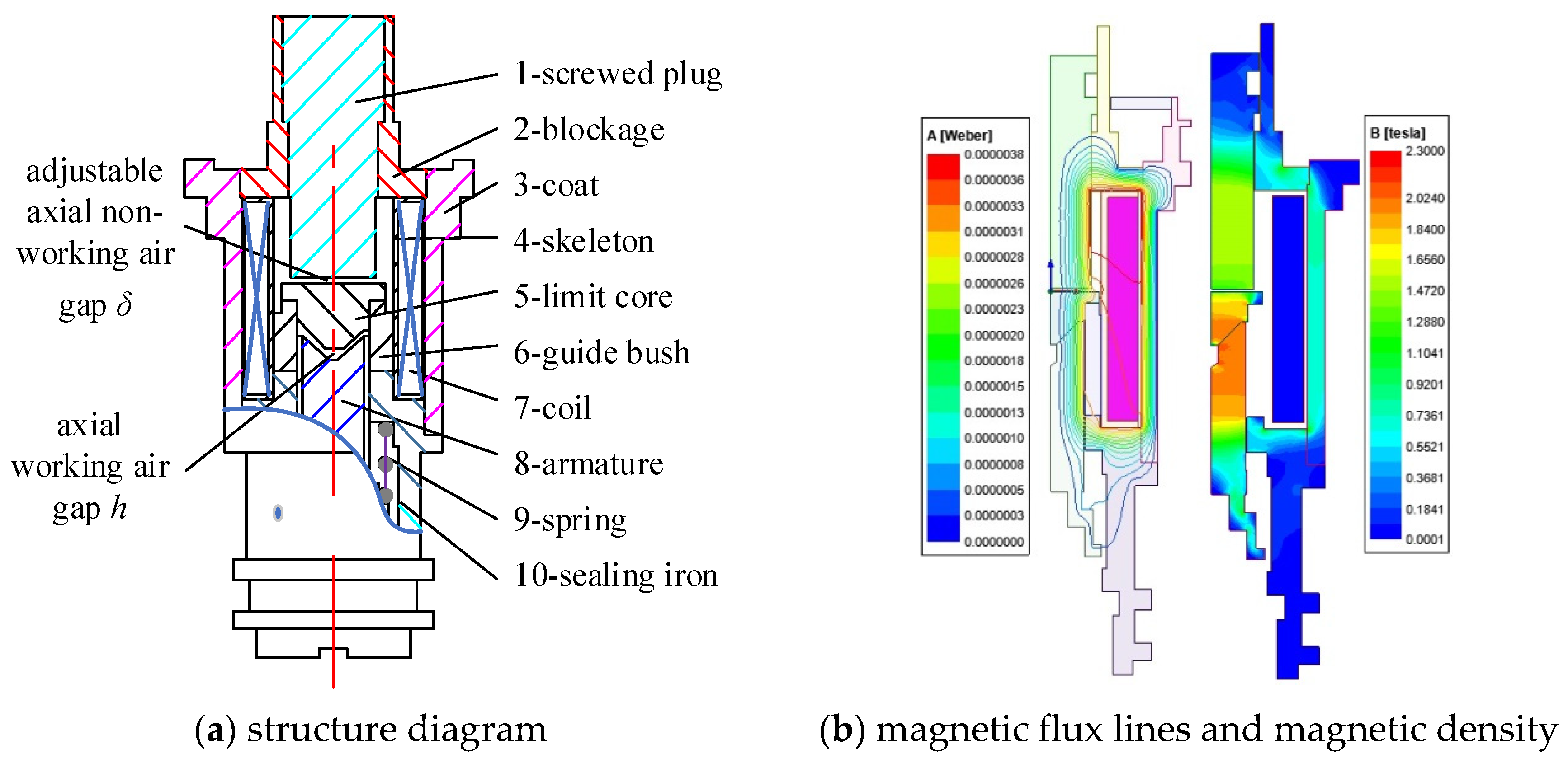
The HFSV introduced in this paper is a normally closed valve. This is an on–off valve that relies on the spring return. The flow of the valve is 1.5 L/min when entrance pressure difference is 1 MPa. The structure, which is divided into electromagnet and valve body, is shown in
Figure 1a. The electromagnet part is mainly composed of the screw plug, plug frame, shell, coil winding, skeleton, limit core, guide sleeve, armature and iron sealing components. The armature is guided by the axial sliding of the sealing iron, the screw plug is connected with the plug frame through the screw thread. An adjustable non-working air gap
δ between the screw thread rotation and the limiting core could be formed in the screw plug. The working air gap
h is formed between the armature and the limiting core.
When the coil is excited, a closed magnetic circuit will be formed along the minimum path of magnetoresistance, through the magnetic components of a screw plug, limit core, armature, iron seal, shell and screwed plug. That is shown in
Figure 1b. Axial electromagnetic attraction will be generated in the axial working air gap. Then, the armature overcomes the forces of spring, friction and damping, and then the valve begins opening. In the state of power failure, the armature would be reset under the action of spring force. The armature is pressed and reaches to the valve seat to keep the valve port be closed.
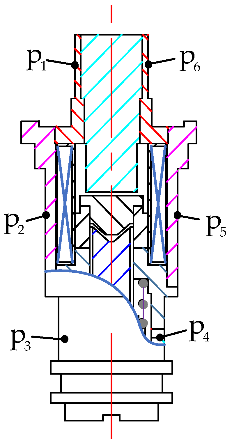
Six different measured positions of surface magnetic density of the HFSV are shown in
Figure 2. The real magnetic density of the HFSV was measured by Gauss meter and compared with the simulation values, as shown in
Table 1. It can be seen that the simulation results are in good agreement with the test results, which verified the correctness of the established simulation model.
3. Dynamic Mathematical Model of HFSV
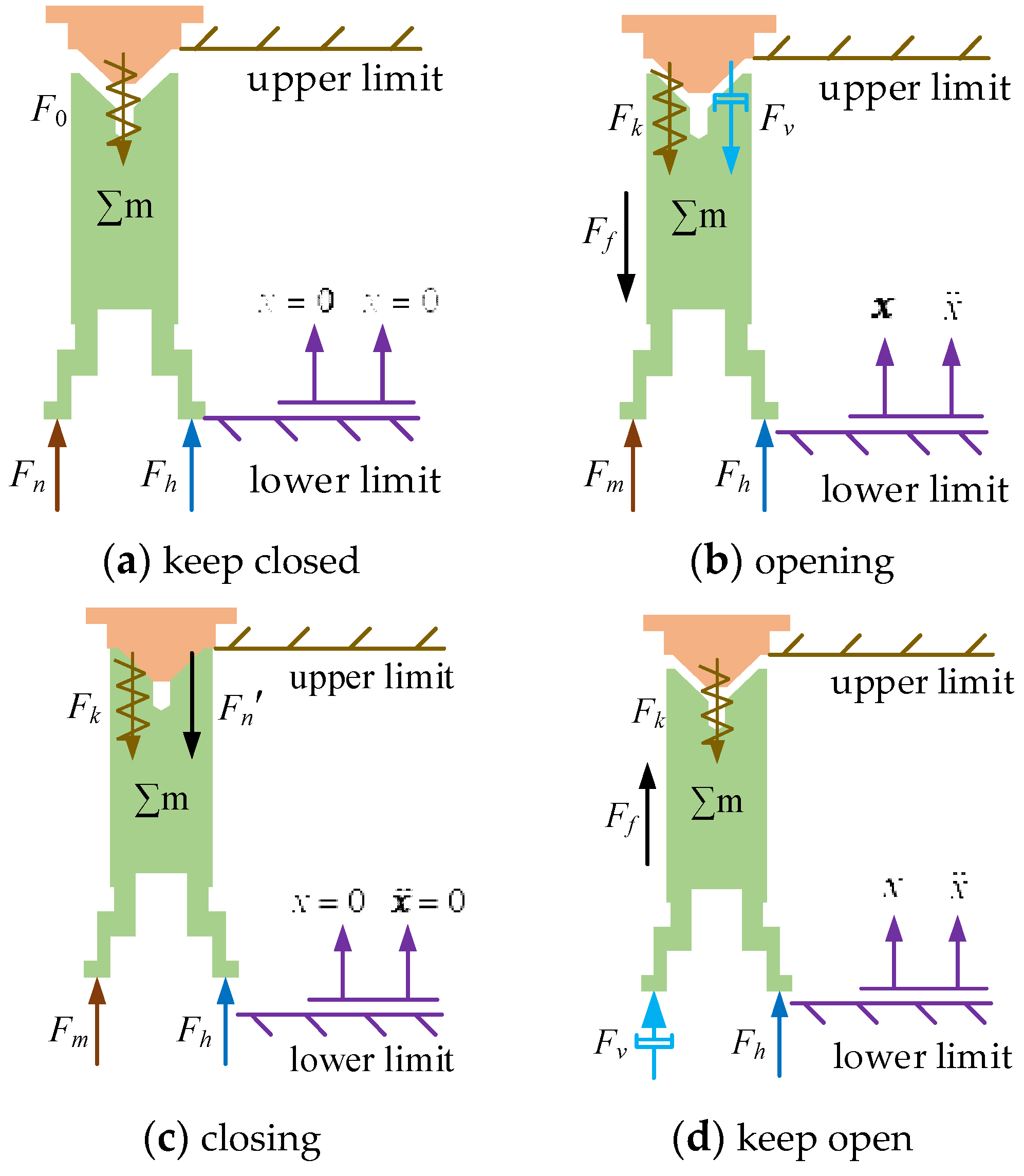
The force of armature in the working state is the combined action of electromagnetic force
Fm, spring force
Fk, friction force
Ff and damping force
Fv. The gravity of armature assembly ∑
mg is very small, which can be ignored. The armature undergoes four states during the working process, which are kept closed, opening, kept open and closing. The force analysis of armature in the four states is shown in
Figure 3.
The force analysis of the armature closing state is shown in
Figure 3a. The coil is not excited, the electromagnetic force
Fm is zero, and the spring preload
F0 is greater than the hydraulic pressure
Fh at the initial position, so that the armature is statically pressed on the valve seat. The force balance equation is:
where
Fn is the force of valve seat on armature (N);
Fh is the hydraulic pressure (N);
F0 is the spring preload (N), 4.5 N.
The force analysis of armature opening state is shown in
Figure 3b. When the coil is excited, the electromagnetic force
Fm is not zero, electromagnetic force
Fm and hydraulic pressure
Fh overcome the spring force
Fk and friction
Ff and damping force
Fv. Then the valve port opens, and then the dynamic equation is:
where
m is the mass of armature assembly (kg);
is acceleration of armature (N);
Fk is spring force (N);
Ff is the friction force of armature (N);
Fv is damping force of armature (N);
Fl is load force on armature.
The force analysis with the valve port kept open is shown in
Figure 3c. After the opening state, the armature moves upward, and the air gap becomes zero. The coil continues to be excited, the electromagnetic force
Fm is not 0, the electromagnetic force
Fm and the hydraulic pressure
Fh are greater than the spring force
Fk, the valve port remains open, and the force balance equation is:
where
Fnʹ is the force of upper limit on armature (N).
The stress analysis of the armature return state is shown in
Figure 3d. The coil is not excited. The electromagnetic force
Fm is 0. The spring force
Fk overcomes the hydraulic pressure
Fh to make the armature closed, and dynamic equation is:
The working load of the spring can be expressed as:
where
k is spring coefficient (N/mm), 500 N/mm;
x is displacement of armature (mm).
The armature generates friction between the sealing iron and the inner wall of the guide sleeve during the action, and forming a friction force against the armature. Because the valve body is immersed in fuel medium, the friction coefficient is small, and the quality of armature assembly is also small, the friction of armature can usually be ignored in previous studies. In this paper, the friction Ff is ignored when analyzing the dynamic characteristics of high-speed solenoid valve.
The damping force of the armature assembly is the viscous resistance between the armature assembly and the fuel medium during the movement. The calculation expression is:
where
ζ is the damping coefficient of velocity (N/(m/s));
v is the speed of armature (m/s).
4. Electromagnetic Modeling
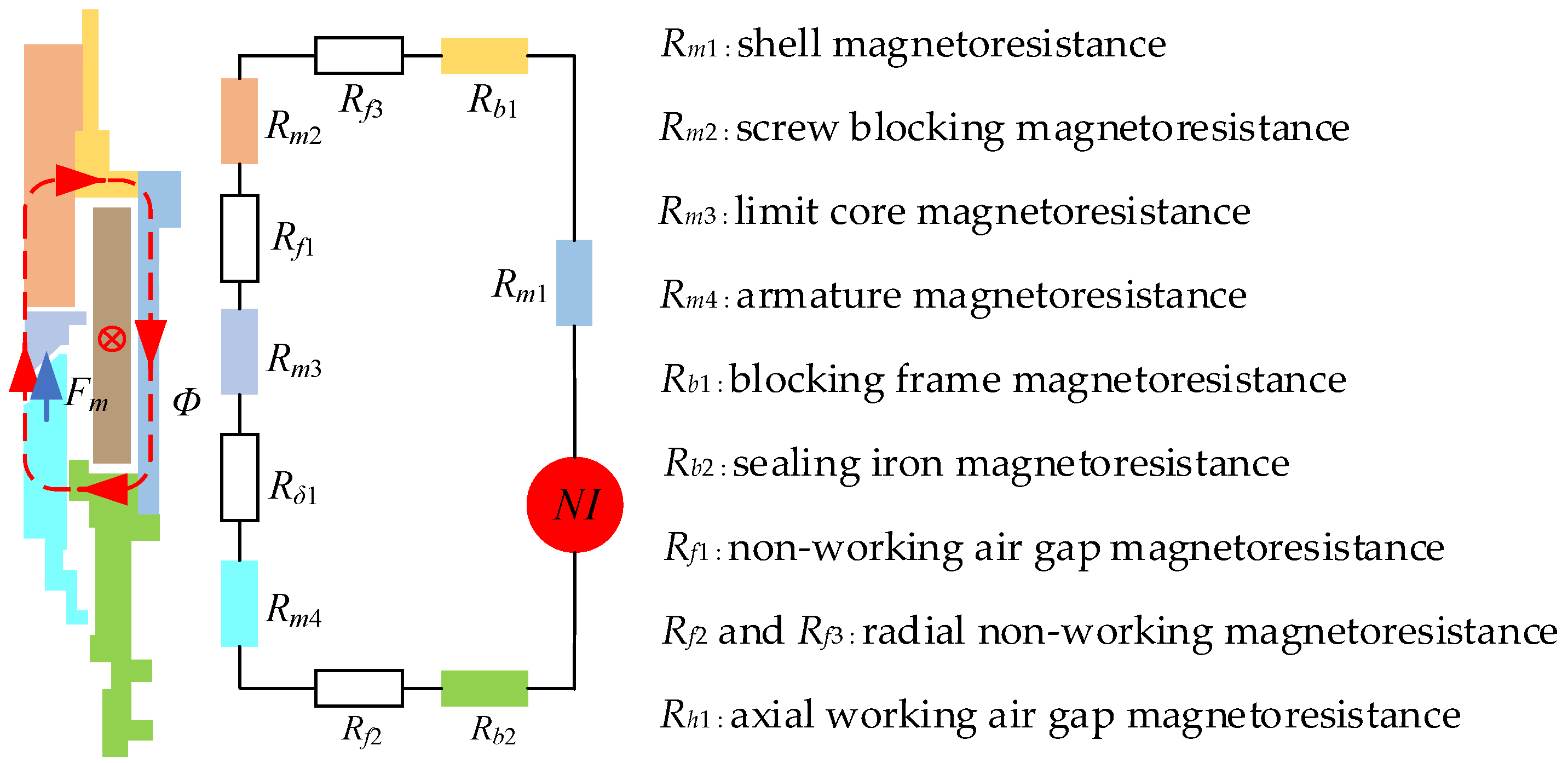
Magnetic equivalent circuit of the HFSV is divided by magnetic circuit segmentation method, as depicted in
Figure 4. The red virtual line represents the path of the main flux
Φ.
NI is defined as the magnetomotive force of the electrified coil.
It can be found from
Figure 2, due to all the magnetoresistances being series connected, that the total magnetoresistance ∑
Rc can be calculated as below.
where Σ
Rm is the axial reluctance of magnetic element (H
−1);
Rh is working air gap magnetoresistance (H
−1); ΣR
f is non-working air gap magnetoresistance (H
−1); Σ
Rb is a magnetic element with radial magnetoresistance (H
−1). The specific sub-items of each reluctance are Σ
Rm =
Rm1 +
Rm2 +
Rm3 +
Rm4, Σ
Rf =
Rf1 +
Rf2 +
Rf3, Σ
Rb =
Rb1 +
Rb2,
Rh =
Rh1.
The axial magnetoresistance of magnetic elements is:
where
μi is the permeability of the magnetic material (H/m);
Lmi is magnetic element length (mm);
Smi is the cross-sectional area of magnetic components (mm
2).
The two parallel circular planar non-working air gap reluctance
Rf1 between the limit core and the screw plug is deduced as:
where
δ is the length of non-working air gap (mm);
μ0 is vacuum permeability (H/m), and equals to 4 π × 10
−7 H/m;
S0 is non-working air gap flux area (mm
2).
The non-working air gap magnetoresistance
Rf2 formed by radial concentric annular surface between armature and seal is deduced as:
where
rf1 is the inner diameter of radial air gap annular plane between armature and sealing iron (mm);
rf2 is the outer diameter of radial air gap annular plane between armature and sealing iron (mm);
Lf1 is the axial thickness of radial air gap of armature and sealing iron (mm).
The non-working air gap reluctance
Rf3 formed by the radial concentric annular surface between the screw plug and the plug frame is deduced as:
where
rf3 is the inner diameter of the radial air gap between the screw plug and the plug frame (mm);
rf4 is the outer diameter of the annular surface of the radial air gap between the screw plug and the plug frame (mm);
Lf2 is the axial thickness of the radial air gap between the screw plug and the plug frame (mm).
The magnetoresistance
Rb formed by the radial concentric annular surfaces of screw plug and iron seal is deduced as:
where
rbi is the inner diameter of the annular surface of the radial magnetic material between the screw plug and iron seal (mm);
rbo is the outer diameter of the annular surface of the radial magnetic material between screw plug and iron seal (mm);
Lbi is the axial thickness of the radial magnetic material of screw plug and iron seal (mm).
The magnetoresistance
Rh1 of axial conical surface working air gap between armature and limiting core can be deduced as:
where
dc is the diameter of conical cylinder (mm);
α is the cone angle of the conical surface (°);
h is the cone axial spacing (mm).
The flux
Φ in the magnetic circuit is calculated as:
where
Φ is magnetic flux (Wb).
Thus, assuming that the magnetic flux is uniformly distributed on the conical surface of the armature, the axial electromagnetic force
Fm of the armature can be calculated as:
where
Fm is the electromagnetic force of the armature (N);
Sm4 is the radial cross-sectional area of armature (mm
2).
6. Key Influence Factors on Static Electromagnetic Characteristic
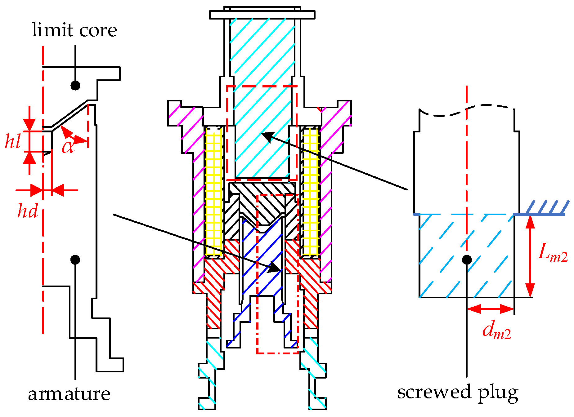
The study of static characteristics is the foundation and steady state of the dynamic response. Base on this, the influence of key parameters on the static characteristics of HFSV was studied. The structural parameters of HFSV electromagnet components are shown in
Figure 9.
The length and radius of the plug screw entry section are Lm2 and dm2, which can be converted into the magnetic flux cross-sectional area Sm2 and the non-working air gap length δ. And the key structural parameters, which is between the armature and limiting core, are those of the conical magnetic pole angle α, armature opening radius hd and hole depth hl.
Magnetic circuit was firstly chosen to investigate the influence of various key factors on the static electromagnetic force. The variation range of the above factors (i.e., magnetic flux cross section area, non-working air gap length, cone angle of armature magnetic pole surface, radius of opening hole of armature and hole depth of armature) is shown in
Table 3. Univariate analysis was adopted, which is when a certain factor variable is investigated, the other parameters will keep constant.
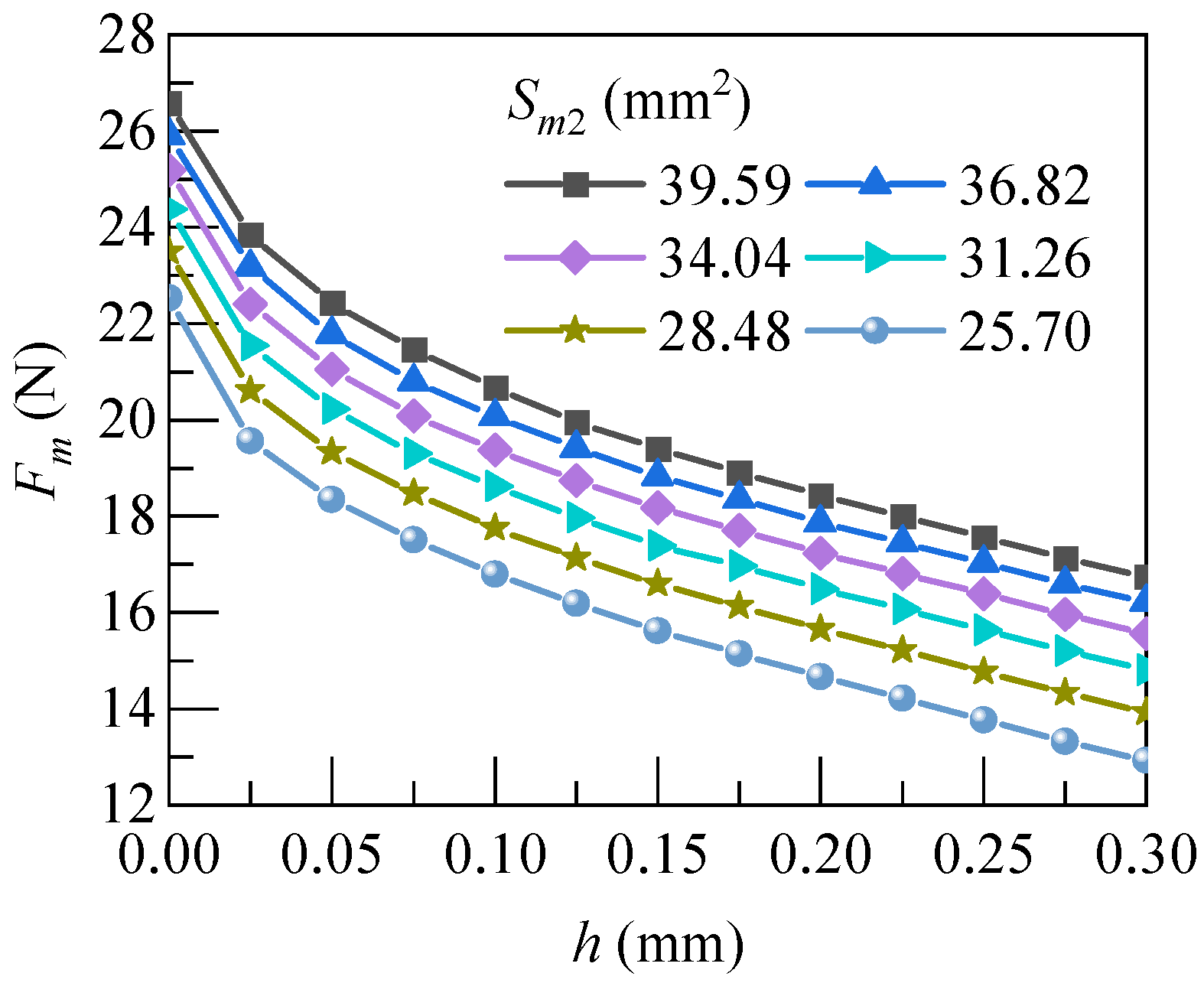
6.1. Magnetic Flux Cross Section Area
Six groups of static electromagnetic force under different magnetic flux cross-sectional area
Sm2 were obtained by adjusting the magnetic pole radius
dm2, as shown in
Figure 10. In this study, the range of
Sm2 was set to 25.70~39.59 mm
2. Under the same working air gap, the static electromagnetic force
Fm of the armature decreases with the decrease in
Sm2. This might be attributed to the excessive saturation of the magnetic induction intensity in the spiral section.
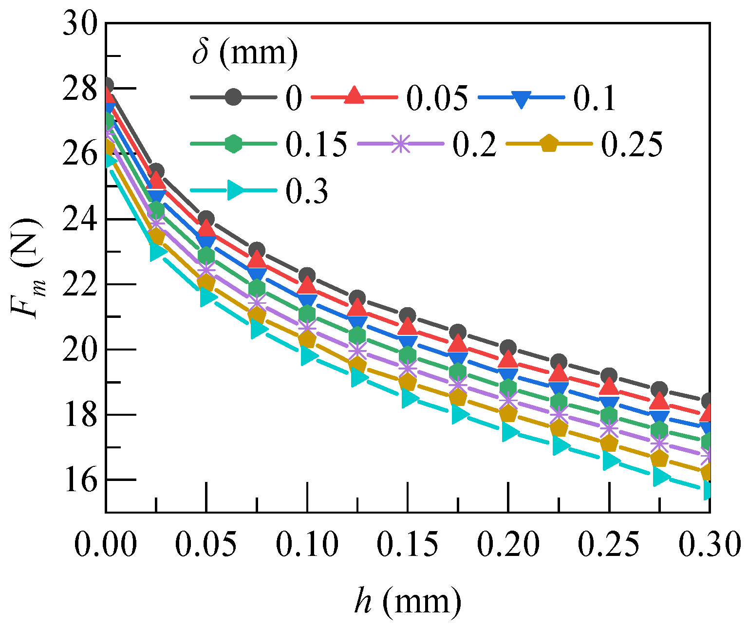
6.2. Non-Working Air Gap Length
After the connection of screw thread with the plug frame, the non-working air gap
δ between the screw thread and the limiting core changed with adjustment of the length
Lm2. Changing of
δ in 0–0.3 mm resulted in the adjustment of the static electromagnetic force on the armature. Variation curves of the static electromagnetic force under different value of
δ is shown in
Figure 11.
The curves showed that the static electromagnetic force Fm of the armature decreased with the increase in the non-working air gap δ under the same working air gap. From Formula (3), with the increase in the adjustable δ, the adjustable non-working air gap reluctance Rf1 increases. When the coil excitation current is constant, the magnetic induction intensity in the magnetic circuit decreased, and resulted in the armature static electromagnetic force Fm decreasing.
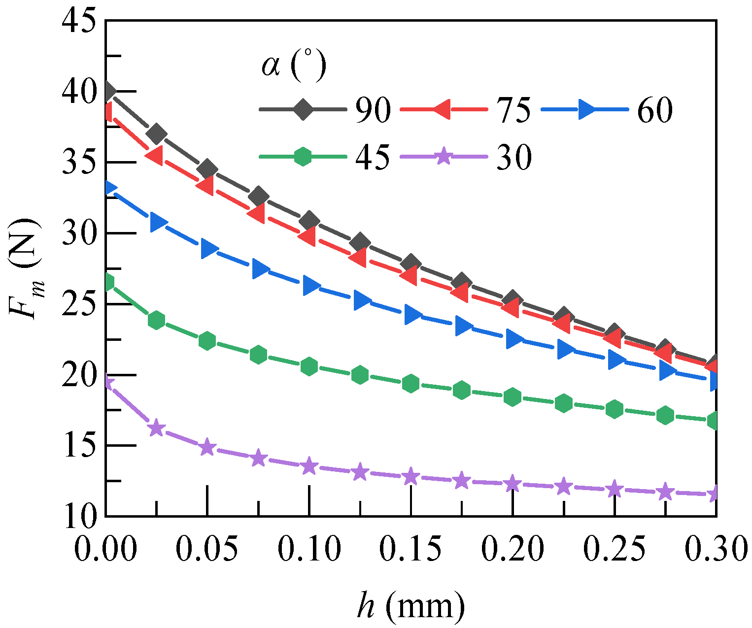
6.3. Angle of Conical Magnetic Pole
The shape of the armature magnetic pole surface was designed as a cone, which makes the trend of the static electromagnetic force curve flatter. The reference value of conical polar angle
α is 45°, and the adjustment range is 30–90°. The static electromagnetic force under the change of conical polar angle α was be obtained by the model, as shown in
Figure 12. Within this working stroke range, the static electromagnetic force
Fm of the armature increased with the increase in the magnetic polar cone angle
α. The increase trend decreased with the increase in the equivalency of the polar cone angle
α. Therefore, the dynamic response performance of the solenoid valve could be improved by adjusting the cone angle
α of the magnetic pole to match the reaction characteristics.
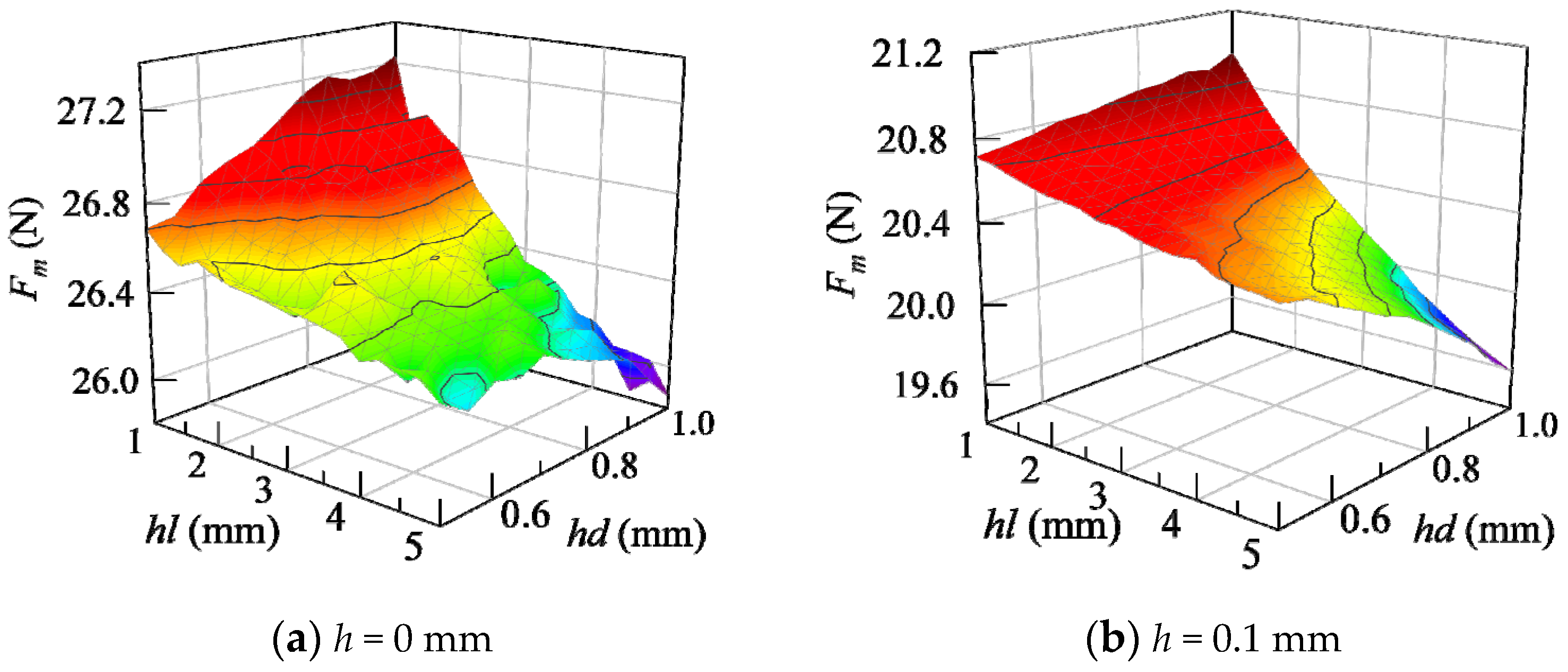
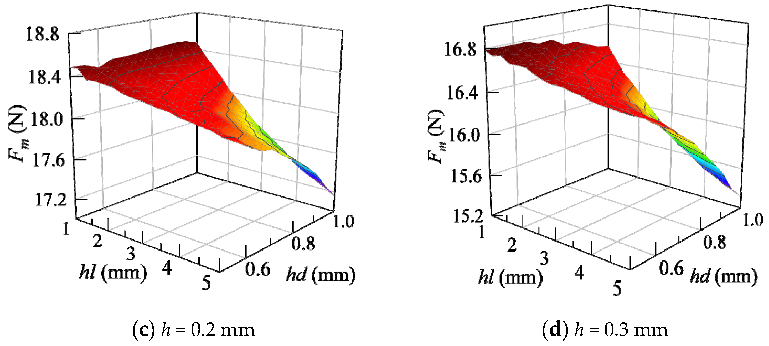
6.4. Opening Size of Armature
As a moving part of HFSV, the armature electromagnetic force has direct influence on the dynamic response characteristics of armature. Thus, the influence of the hole size parameters on the static electromagnetic force of the armature was studied. The hole radius
hd is 0.5 mm, the hole depth hl is 1.5 mm, the hole radius
hd is 0.5~1 mm and the hole depth hl is 1~5 mm. The static electromagnetic force with the change of the hole radius
hd and the hole depth hl was recorded, as shown in
Figure 13.
Figure 13 shows that the static electromagnetic force
Fm under each working air gap
h decreased with the increase in
hl and
hd. That’s because the magnetic induction intensity of the ring area at the upper end of the armature reaches saturation as
hd and
hl grow. Additionally, reduction of the contact area resulted in the decrease in the static electromagnetic force
Fm of the armature. However, the magnetic induction line was almost unable to pass the opening at the upper end of the armature, resulting in the limited variation of the static electromagnetic force
Fm of the armature.
7. Taguchi Method Based Structural Optimization
The Taguchi method can be used to realize multi-objective optimization design [
23,
24,
25,
26]. By establishing an orthogonal table, the results of multi-objective optimization design parameters can be searched in less test time. The core idea of the Taguchi method is to apply the robust design to the product [
25,
26,
27,
28]. To optimize the products, it is necessary to look for the best combination of controllable factors, which could make the response variables more in line with the test requirements.
The specific calculation process of the Taguchi method is as follows:
The total mean of all tests:
where
M(S) is the total mean;
i is the number of tests;
Si is the result of the experiment
i;
n is the number of orthogonal experiments.
Average value analysis can be expressed as:
where
MX(j)(
S) is the average of the optimization objectives at the level
j of the specific control factor
X;
X is a specific control factor;
j is a certain level of the specific control factor;
τ is the test result data of a specific control factor at this level.
Analysis of variance is:
where
SSDX(S) is variance of optimization object of factor
X;
n is the level number.
SS0,
SS1,
SS2 and
SS3 are variance of optimization object of factors, which is
SSDX(S) in Equation (12).
In the above single-factor analysis, the levels and ranges of the optimization variables of the experimental design model are determined. The number of test calculations is set to 9. The model of HFSV was numerically simulated according to the test scheme. The number of coil excitation turns is 674.5 A. The factors and levels of test design optimization variables are shown in
Table 4.
The test matrix and finite element simulation results are shown in
Table 5. The average test values under the four different working air gaps are 29.06 N, 21.35 N, 17.87 N and 15.35 N, respectively. The proportion of the influence of optimization variables on the static electromagnetic force under four working air gaps is shown in
Table 6. In this table, when
h = 0 mm, the proportion of α is the largest, so it can be obtained that its influence on the electromagnetic force is the largest at the suction position, so the angle with large electromagnetic force is preferred. Similarly, in other positions, the influencing factors with a large proportion are preferentially selected, and then the parameters that can generate a large electromagnetic force are selected according to their influence law on the electromagnetic force.
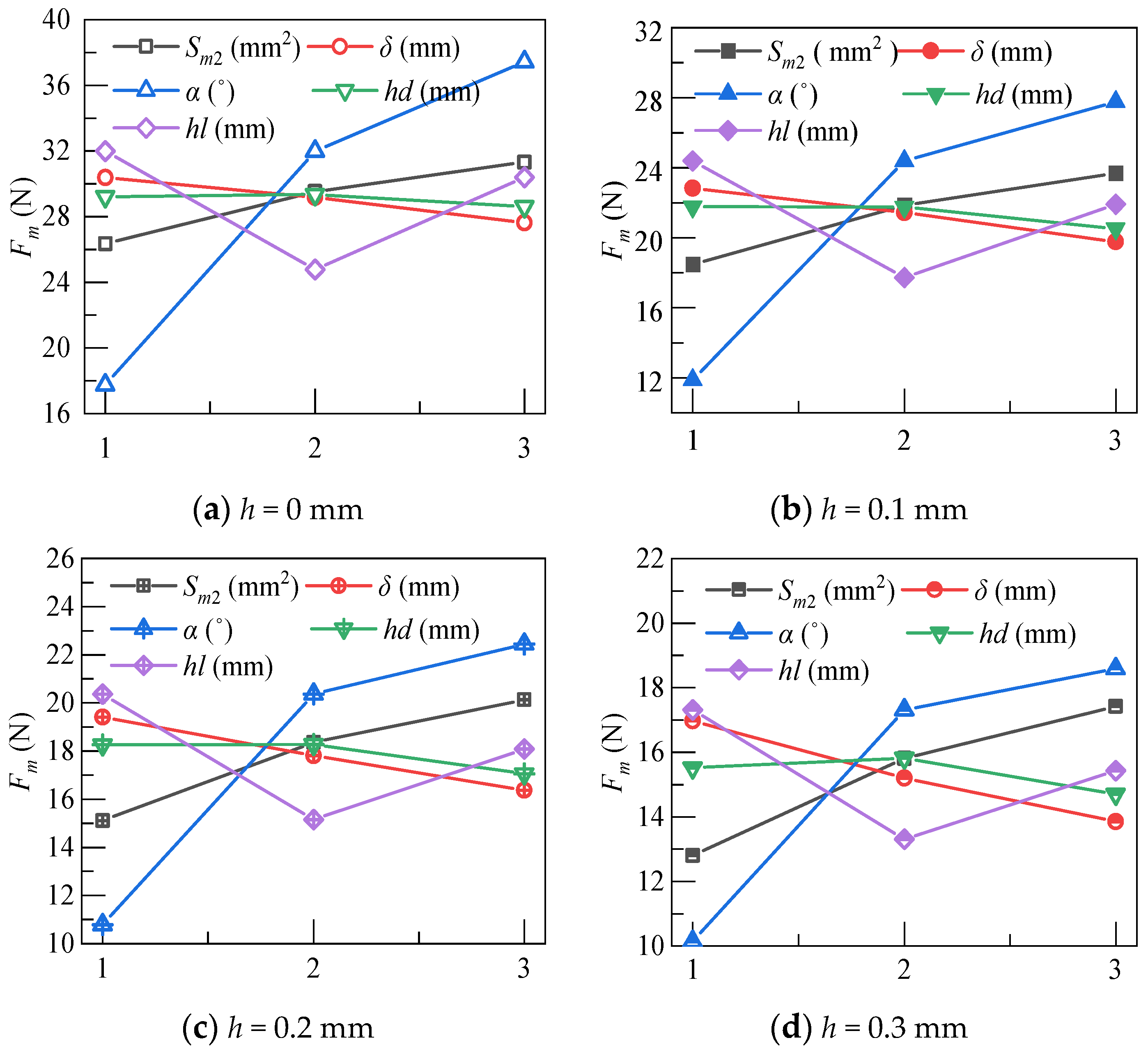
The influence trend of five variables on the static electromagnetic force
Fm under four working air gaps is shown in
Figure 14. It can be seen that the most obvious variable affecting the static electromagnetic force is the cone angle
α, followed by the depth of the armature opening hole
hl, the magnetic flux cross-sectional area
Sm2, the length of the non-working air gap
δ and the radius of the armature opening hole
hd.
The optimal structural design factors combination for the maximum static electromagnetic force is
Sm2 (3)
δ (1)
α (3)
hd (2)
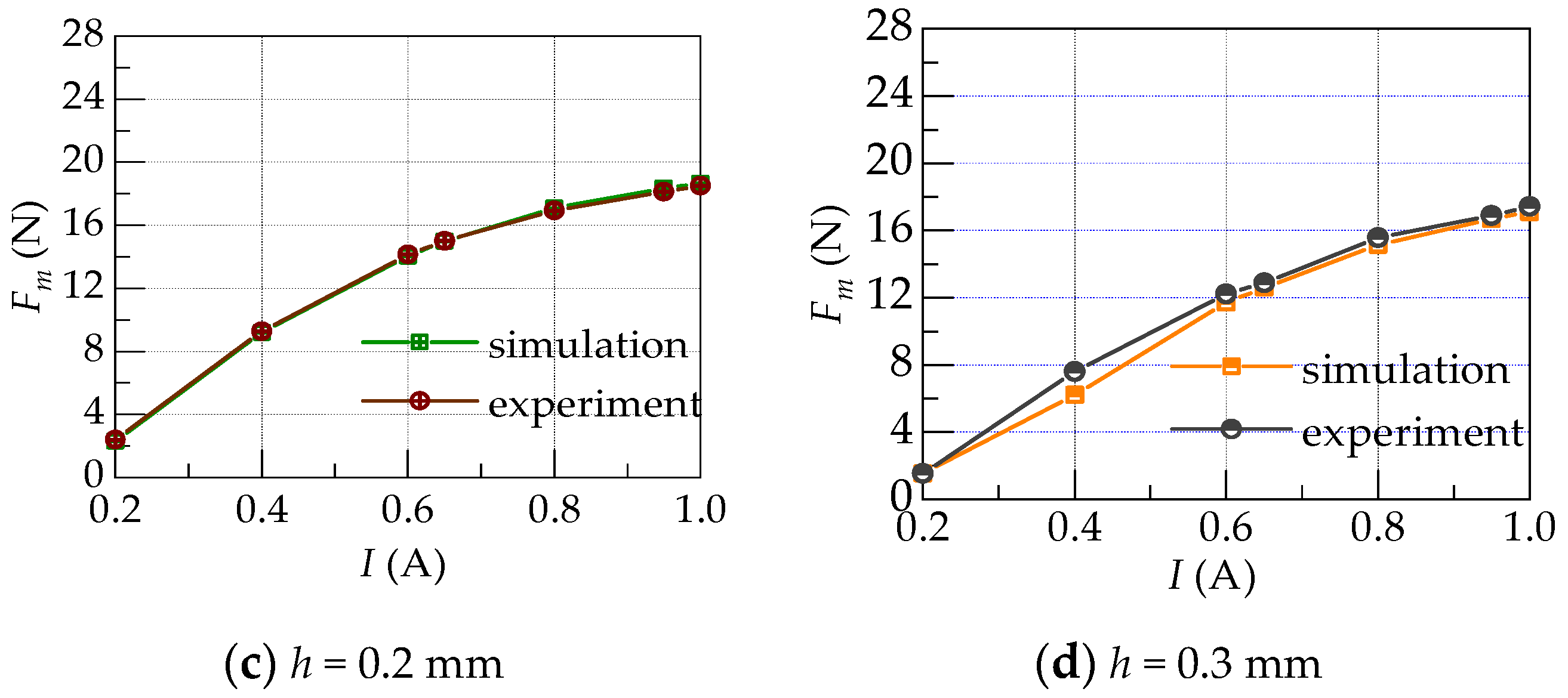
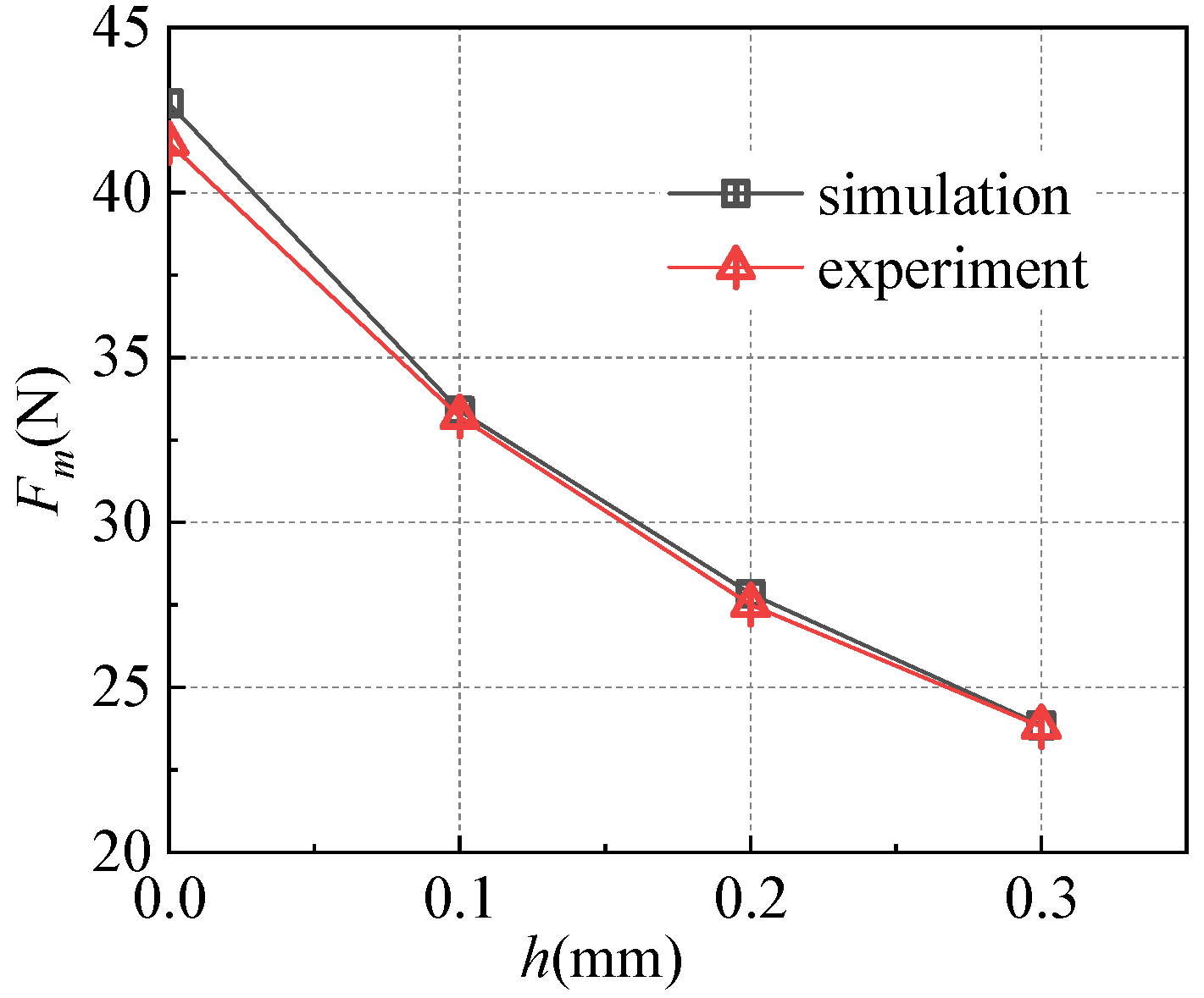
hl (1). Meanwhile, the optimized HFSV prototype was manufactured and tested. In
Figure 15, the experimental value is compared with the simulation under different working air gap. The experiment results are in good agreement with the simulation ones. The results before and after optimization are shown in
Table 7. It can be found that the static electromagnetic forces are increased by 60.65%, 61.56%, 51.04% and 42.48%, when the working air gap position is 0 mm, 0.1 mm, 0.2 mm and 0.3 mm, respectively.


 ,
, 


