1. Introduction
Stroke has a poor prognosis and is becoming the leading cause of permanent disabilities worldwide, with over 15 million new cases each year and 50 million stroke survivors, which can cause neurological and functional impairments and affect the patients’ daily activities [
1]. Most stroke survivors have lower limb mobility deficits [
2]. For the reason that manually assisted training for lower limbs requires intensive labor from the physical therapist, many different lower limb rehabilitation robots (LLRRs) have been developed in the last two decades, such as those commercial products including LOPES [
3], ALEX [
4], ReWalk [
5], Indego [
6], et al. In addition, many other LLRRs have also been studied with different mechanisms for different application scenarios and patient populations.
To design and analyze the configuration of the mechanical structure from different perspectives and face different application scenarios, many researchers have developed LLRRs. A passive lower limb exoskeleton with hip and knee joint is proposed for walking assistance to save powers and reduce the LLRR’s weight and its complexity of the mechanism, which is designed with built-in spring mechanisms for gravity compensation of the human leg [
7]. To help patients quickly and accurately transmit the motion intention to the robot and reduce the possibility of falls and errors, Liu et al. developed a vision-assisted autonomous lower-limb exoskeleton robot based on the principles of human visual feedback and motion decision-making [
8]. To reduce the size and mass of the conventional LLRRs, Wang et al. developed a hybrid end-traction LLRR by using the hybrid mechanism
and a mirror motion actuator [
9]. To deliver post-stroke therapy to both upper and lower extremities, Chole et al. developed an active mobile end-effector foot-plate/handle grip robot, which has features including dual-usability, lightweight design, mechanically adjustable maximum forces and torques, inherent safety, portability, and teleoperation capability [
10]. To probe and promote motor adaptation and volitional movement, Alexander et al. developed one degree of freedom (DOF) rehabilitation robot named NOTTABIKE, which can render both impedance- and admittance-based haptic environments with accuracy and responsiveness that are useful for the study of human coordination and the delivery of rehabilitative therapy [
11]. In addition to the different configurations, different control strategies have been developed for LLRRs, to improve their gait training performance using passive exercise or improve the rehabilitation training performance with patient-active exercise. From the above researches, we can see that although many different mechanisms related to LLRR have been studied, relatively little has been done with rigid-flexible characteristics.
In addition to the mechanism design, the control algorithms of the LLRRs are also very important. To overcome the situation that the patients must acquire the ability to maintain their balance and shift their weight using forearm crutches, which is challenging for paraplegics, Ma et al. proposed an automated intelligent gait planning method that integrated a finite-state machine model as an underlying foundation and a gait generation model in addition to the exoskeleton system [
12]. To target a specific muscle group during a functional task such as simulated walking, the indirect control scheme based on a computational model of the human musculoskeletal system is proposed in [
13], which searches for the optimal load along the predefined path to maximize the efficiency of muscle training. To achieve the predetermined angular trajectories, the Lyapunov adaptive and swarm-fuzzy logic control strategy was implemented on a 4-DOF lower limb assistive robot, in which the control law is an integration of swarm-fuzzy logic control (SFLC) and Lyapunov adaptive control (LAC) that are improved by particle swarm optimization (PSO) [
14]. To improve the safety and tracking performance of an LLRR, Liu et al. presented an application of the variable stiffness actuator (VSA)-based assistance/rehabilitation robot-featured impedance control using a cascaded position torque control loop; The robot follows the adaptive impedance control paradigm, thereby achieving an adaptive assistance level according to human joint torque [
15]. To plan the subject’s desired trajectory based on interaction force during physical human-robot interaction, Zhou et al. developed a trajectory deformation algorithm as a high-level trajectory planner, which can improve robot compliance and movement smoothness [
16]. To solve the problem that a significant gait deviation may occur between the gait trajectory of the wearer and the reference trajectory, Zhang et al. proposed a gait deviation correction method to decrease the gait deviation for lower limb exoskeleton robots [
17]. Although many control strategies of the LLRRs as mentioned above have been studied, we can see that most of the research is aimed at improving the performance of gait planning and trajectory tracking, and few studies on multimodal rehabilitation training methods have been carried out.
In this work, we developed an LLRR with rigid-flexible characteristics and multi-mode exercises based on our previous researches on rehabilitation robot, including improving the compatibility of upper limb rehabilitation robot with improved mechanism [
18] and developing different rehabilitation training methods with compliance control [
19]. The paper is organized as follows.
Section 2 demonstrates the mechanism design with rigid-flexible characteristics.
Section 3 presents the control system and multi-mode rehabilitation training methods in detail. Experiments and results are displayed and discussed in
Section 4, while conclusion is drawn in
Section 5.
2. Mechanism Design with Rigid-Flexible Characteristics
2.1. Mechanism Design and Compatibility
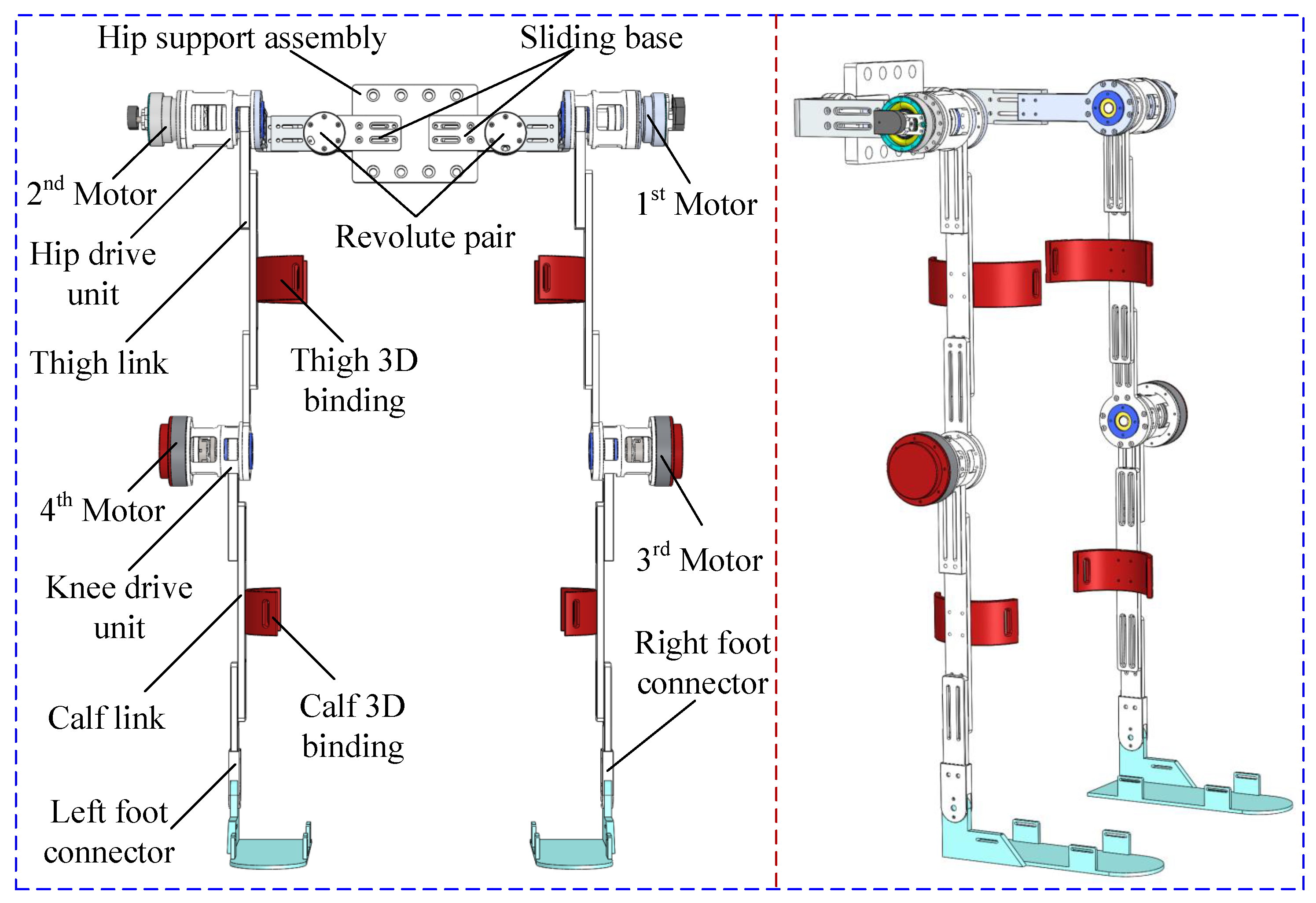
The prototype of the LLRR mainly consists of the hip support assembly, left and right leg motion systems, and leg bindings. Both sides of the hip support assembly are connected with the left and right leg motion systems, respectively. The components of the left and right leg motion systems are completely symmetrical and identical. Each motion system has a hip joint drive unit, a knee joint drive unit, and a lower limb link (thigh, calf, and foot). The hip joint drive unit and the knee joint drive unit are respectively driven to rotate by motors, and the leg links connect and support the drive units. In addition, the leg bindings are used to connect the human’s lower limbs and the LLRR. The detailed mechanical design of the LLRR is shown in
Figure 1, wherein, the hip support assembly has a fixed support seat, a pair of prismatic pairs, and a pair of sliding pairs, and the distal ends of the two sides are connected with the hip joint drive unit. Due to the symmetry of the LLRR’s structure, one side is taken as an example for description. The hip joint driving unit is connected with a thigh link, one side of the knee joint drive unit is connected with the thigh link and the other side is connected with the calf link. Both the thigh link and the calf link are provided with a chute, which can form a prismatic pair with the output rods of the hip joint and knee joint drive units, respectively. The length of the leg link can be fixed by bolts when the robot works.
In order to realize the human-machine compatibility of human hip and knee joints in rehabilitation training, we specially added corresponding passive joints in the mechanism design. The revolute pair in the hip support assembly allows the left and right leg motion systems to carry out adduction and abduction movements; the calf binding and the calf link have a sliding pair, which makes the LLRR’s knee joint and the human’s knee joint indistinguishable during the movement, with no special adjustment of center axis alignment required. Based on the sliding pair and the revolute pair mentioned above, the LLRR can generate passive deflection of the displacement and angle within a certain range to compensate for the error of the human-machine joint, thereby improving the compatibility between the human and the robot. By adjusting the hip support component and the prismatic pair in the leg link, the length of the LLRR’s hip and legs can be adjusted according to the different body sizes of the patients. The adjustment range of the hip width is 39∼47 cm, the leg length is 75∼100 cm, and the height is 155∼180 cm, thereby improving the versatility of the robot.
2.2. Principle and Implementation of the Rigid-Flexible Characteristics
To enhance the safety of the LLRR from the mechanism design, a flexible joint is mounted in the knee drive unit, with one end fixed to the motor output shaft and the other end fixed to the leg link. The purpose of the design is to transmit the torque from the motor to the leg link, and to provide a buffer space between the motor and the joint, thus increasing the compliance of the mechanism.
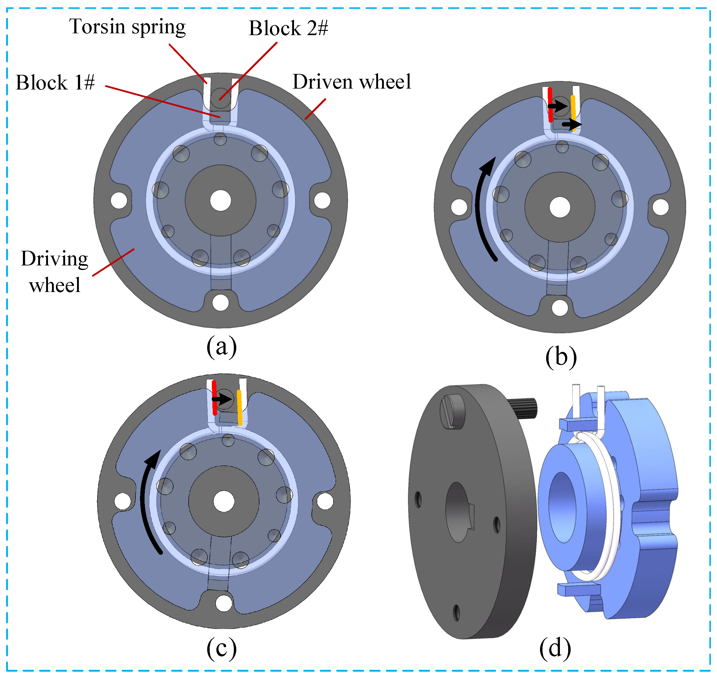
Usually, rigid joints are used to ensure precise motion trajectories, while in the mechanism, the torsion springs are connected in series in flexible joints to achieve compliance. The rigid-flexible characteristics of the LLRR are obtained by the combined design of rigid components and torsion springs. As shown in
Figure 2, the flexible joint consists of a torsion spring and two rigid wheels (made of aluminum alloy material) in series, which have the same axis of rotation. The driven wheel has a first limit block which is connected with the output shaft, while the driving wheel has a first limit block and a chute, which is connected to the motor. The torsion spring is arranged between the driving wheel and the driven wheel, and the torsion arms of the torsion spring are staggered, and the first limit block and the second limit block are clamped in the two torsion arms. Because of the existence of the spring, the second limit block in the initial position is located in the middle of the chute and does not contact the driving wheel. When the motor drives the driving wheel to rotate, the driving wheel and the driven wheel rotate relative to each other, and the second limit block is not in contact with the chute. At this time, the first limit block on the driving wheel drives one torsion arm of the torsion spring to rotate, the other torsion arm drives the second limit block to rotate, and the driving wheel and the driven wheel transmit torque through the torsion spring. When the second limit block is in contact with the chute, the driving wheel, and the driven wheel are approximately fixed together and can be regarded as a rigid whole. At this time, the driving wheel directly transmits the torque to the driven wheel to drive it to rotate. Since the second limit block can only rotate in the chute of the driving wheel, the range of the torque provided by the torsion spring for the second limit block is within a fixed
angle.
In the selection of the torsion spring, a torsion spring with a wire diameter of 1.5 mm, an angle width of , and an outer diameter of 34 mm is used. After being assembled to the driving wheel, it has a torsion range of . When the torsion angle of the joint exceeds the set value, the transmission between the driving wheel and the driven wheel changes from flexibility to rigidity. Using this structure as the connection between the motor and the leg drive rod allows the patient’s joints to still have room for adjustment during the rehabilitation training process. Therefore, although a small amount of position control accuracy is sacrificed when the motor drives the leg link to drive the lower limbs of the human body, its property of storing and releasing torque acts as a buffer and shock absorber for joint rotation, thus to reduce the discomfort caused by limbs being bound and improve the compliance and compatibility.
2.3. Design of the Driving Unit
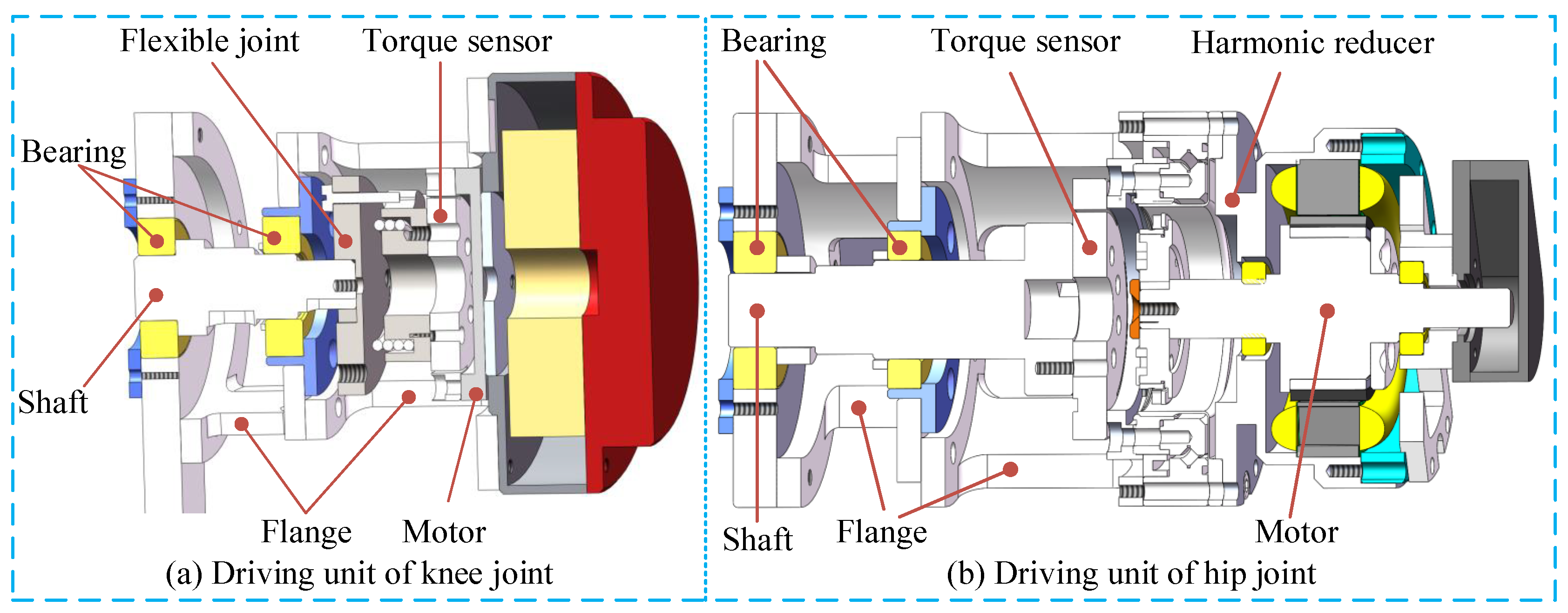
The developed LLRR has four active driving units, including two hip joint driving units and two knee joint driving units. The hip joint units are as shown in
Figure 3a, which are driven by two servo motors (TBMS-6013-A00, Kollmorgen, Waltham, MA, USA), with each servo motor providing a torque of 0.413 Nm. The servo motors are also deployed with harmonic reducers (LHD-17–100-C-I, Leader Harmonious Drive Systems Co., Ltd., Suzhou, China, with a reduction ratio of 1:100), thus can output a maximum torque of 41.3 Nm, which can provide a strong power for the LLRR to drive the lower limbs of the human body. On each side, the reducer is fixedly connected to a torque sensor (M2210E, SRI, Nanning, China, with a capacity of 60 Nm) through the flange, and the other side of the torque sensor is fixedly connected to the main shaft
, so the main shaft and the servo motor at the hip joint are rigidly connected. The knee joint units are as shown in
Figure 3b, which are driven by two joint motors with internal drive (HT-03, HAITAI Electromechanical Co., Ltd., China, with continuous torque 6.9 Nm). The motor output shaft is directly connected to the torque sensor (M2210E, SRI, Nanning, China), the other side of the torque sensor is fixedly connected to the driving wheel of the flexible joint, and the driven wheel of the flexible joint is fixedly connected to the main shaft; Therefore, there is a flexible connection between the motor at the knee joint and the main shaft. All the four motors are deployed with incremental encoders to obtain the corresponding angular velocity and angular acceleration.
3. Control System and Multi-Mode Rehabilitation Training Methods
3.1. Control System of the LLRR
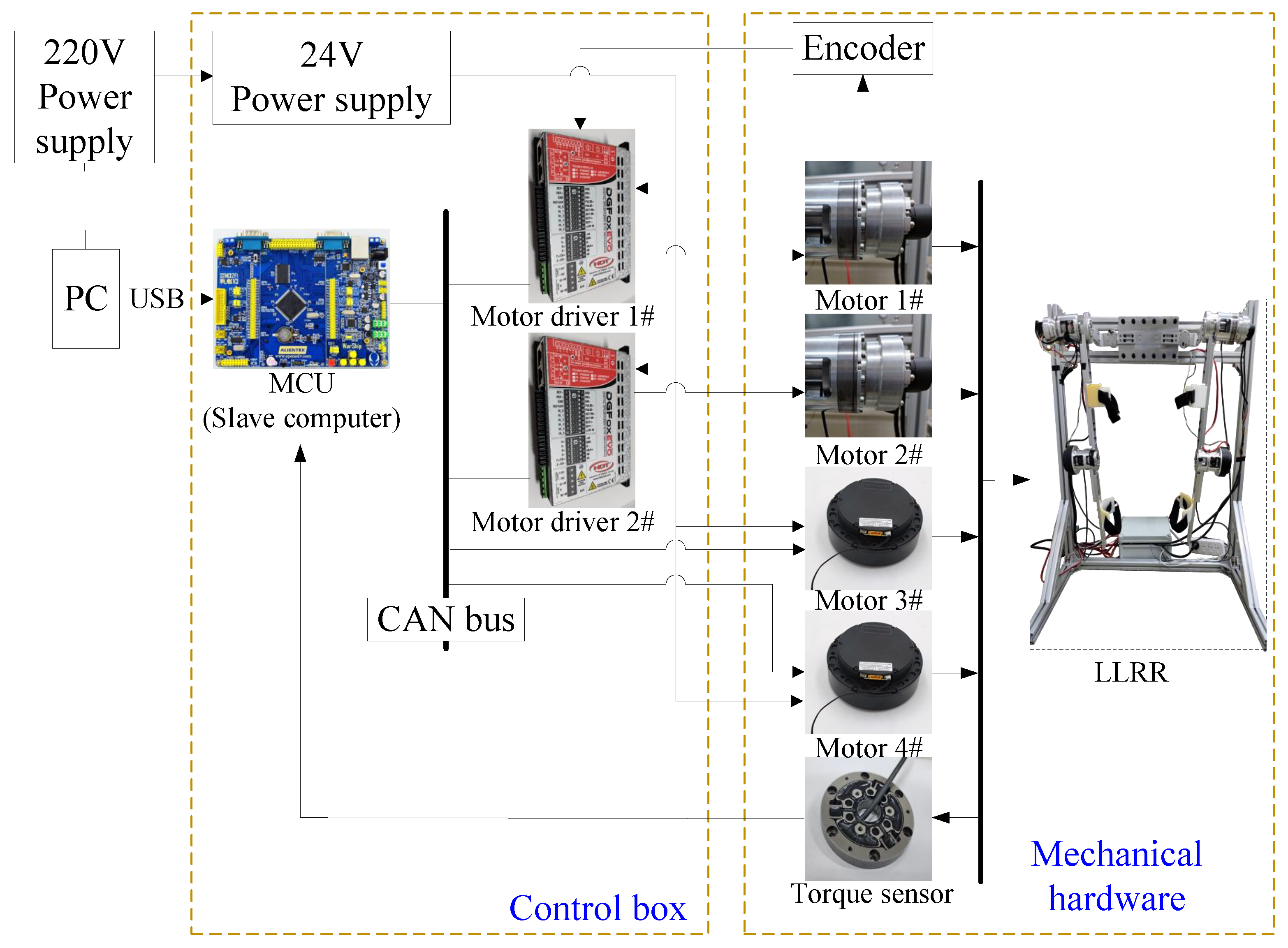
The LLRR adopts the master-slave distributed control, which mainly includes human-computer interface, STM32 microprocessor, servo motor drives, servo motors, and torque sensors, with the whole control system shown as in
Figure 4. The two servo motors in the hip joint units are driven by two DGFox DX060 drives (HDT, Monte Di Malo, Vicenza, Italy), which have good interpolated position modes using the CANopen DS402 Protocol. The torque sensors and the encoders are used to collect torque and angle information of the LLRR.
Based on the developed control system, three different rehabilitation training modes have been developed, namely, passive exercise, active exercise and resistance exercise, respectively.
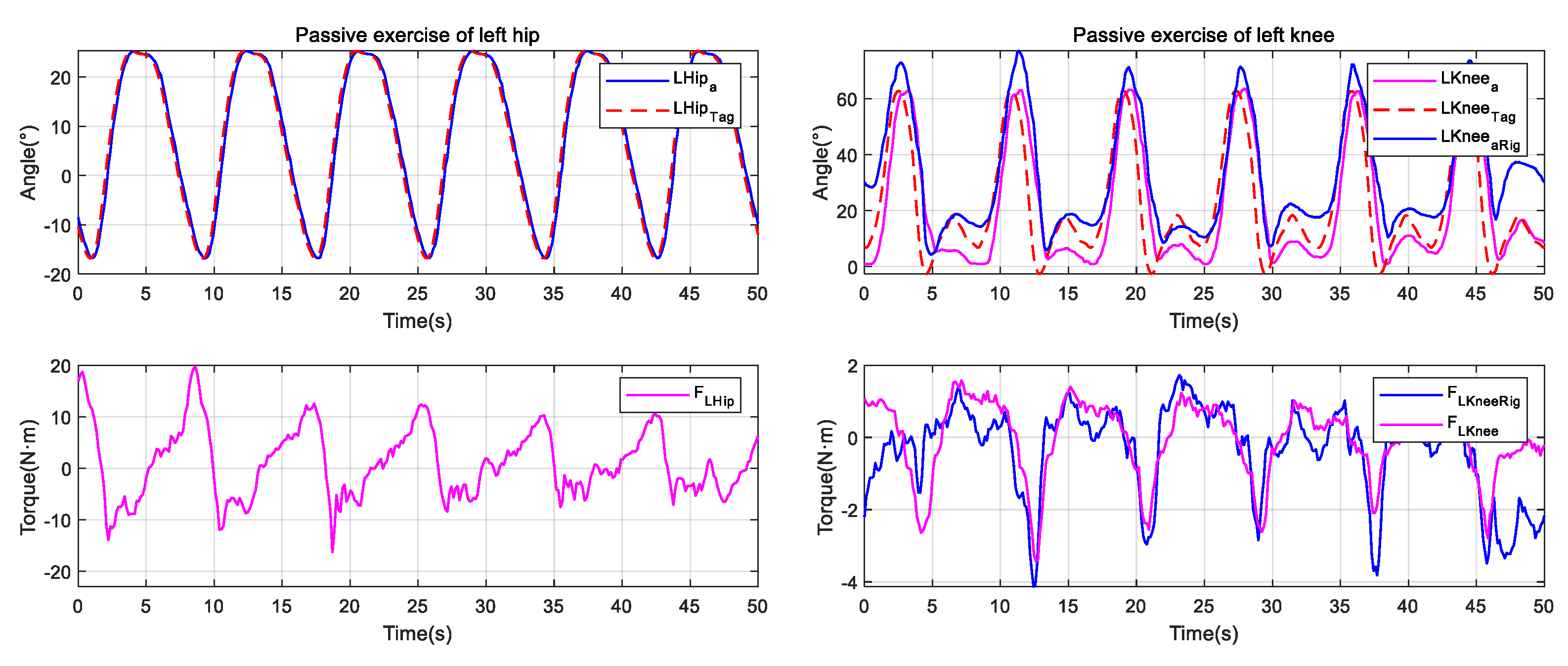
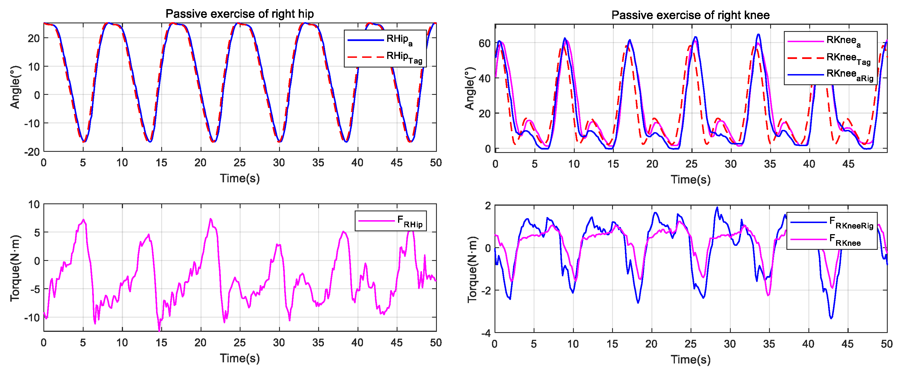
3.2. Passive Exercise
Passive exercise is suitable for the early stage of patient’s rehabilitation training. At this stage, the LLRR needs to provide support and assist the patient’s legs to walk according to the specified trajectory, thereby helping the patient to restore joints’ ranges of motion and muscle strength. Generally speaking, passive exercise does not consider human’s participation, and mainly relies on the robot to drive the patient’s hip and knee joints to produce extension and flexion movement, which promotes the contraction and relaxation of lower limb muscles, tendons, ligaments, etc., and improves the activity of related tissues, prevents limb muscle atrophy.
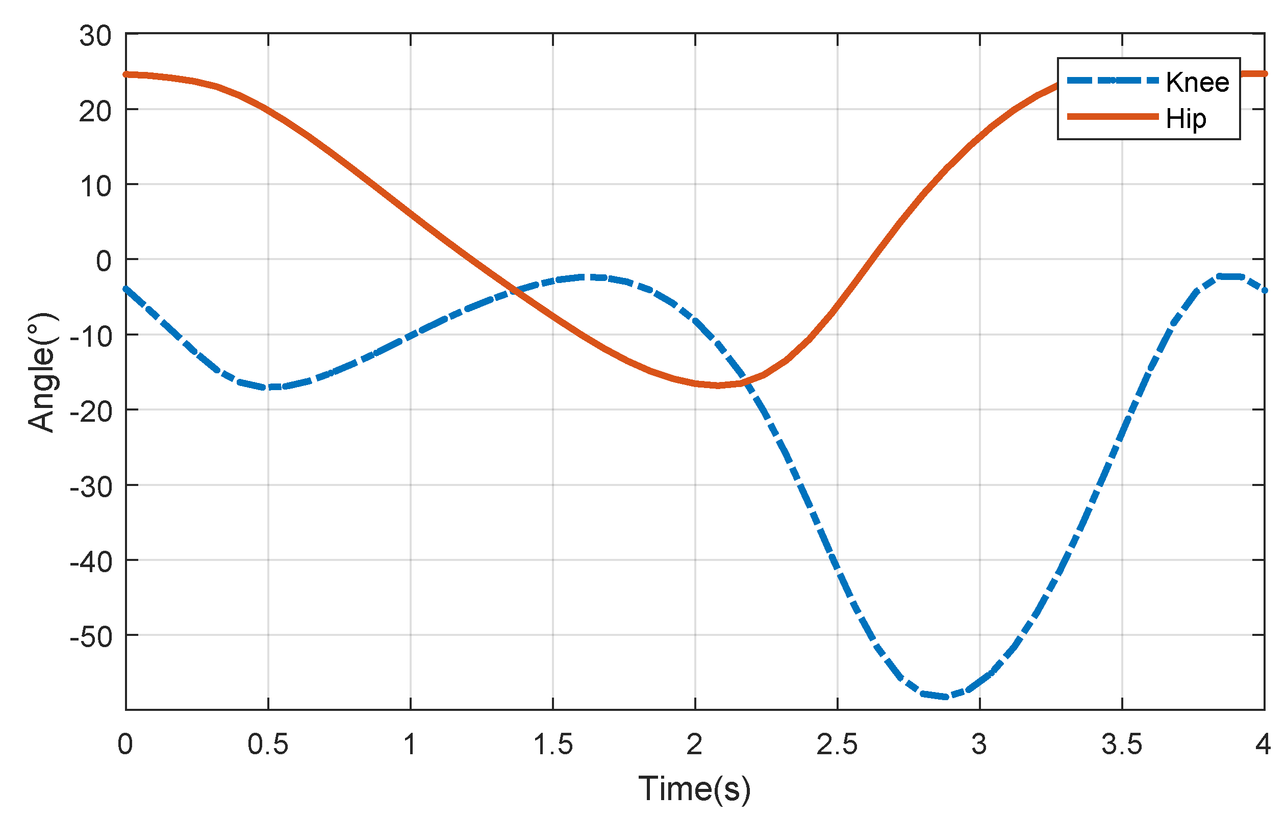
The motion data of normal human’s gait used in passive exercise comes from OpenSim software (developed by Stanford University), with one gait cycle 1 s. In order to obtain the tracking curve for training, the discrete data points in the gait are fitted by using MATLAB (MathWorks. Inc., Natick, Apple Hill Campus, MA, USA), and the coefficient that minimizes the residual error is found. The final equation of the design trajectory for passive exercise is as in (
1). Considering that the gait speed of the patient during the rehabilitation process is low, the gait must be adjusted according to the actual rehabilitation needs. Therefore, the gait cycle of the LLRR is set to be 4 s, and the amplitude coefficient
a, the frequency coefficient
, the initial phase
and the offset distance
k in the standard gait are adjusted to obtain a suitable new gait.
The fitting curves of the hip and knee joints can be obtained as shown in
Figure 5. For the reason that the gait of the human body in the walking stage has periodicity and symmetry, the gait trajectory of the human body in the whole cycle can be deduced according to the acquired new gait.
The multi-order trigonometric function expression of the hip joint is as in (
2), while the function expression of the knee joint is as in (
3).
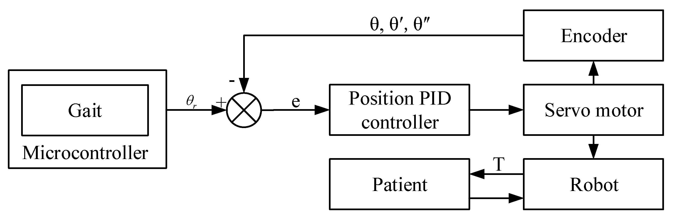
The specific implementation method of passive exercise is as the following. First, we set the training mode as passive exercise mode in the human-robot interface (HRI) which is coded by using C#, convert the desired motion trajectory into the motion angle of each servo motor, and send the angle information to the MCU, and the MCU will convert the angle information to CANopen communication message and sent to the servo driver; then, the LLRR can be controlled to conduct passive exercise. At the same time, the joint motion information collected by the encoder is fed back to the control system to form a closed-loop control, so as to realize the real-time monitoring and tracking of the LLRR’s motion trajectory. The flow chart of the passive exercise is shown as in
Figure 6, where,
,
and
represent the motor joint angle, angular velocity and angular acceleration during the rehabilitation training process, respectively;
e and
T represent the angle error and human-robot interaction torque, respectively; the
is the reference trajectory.
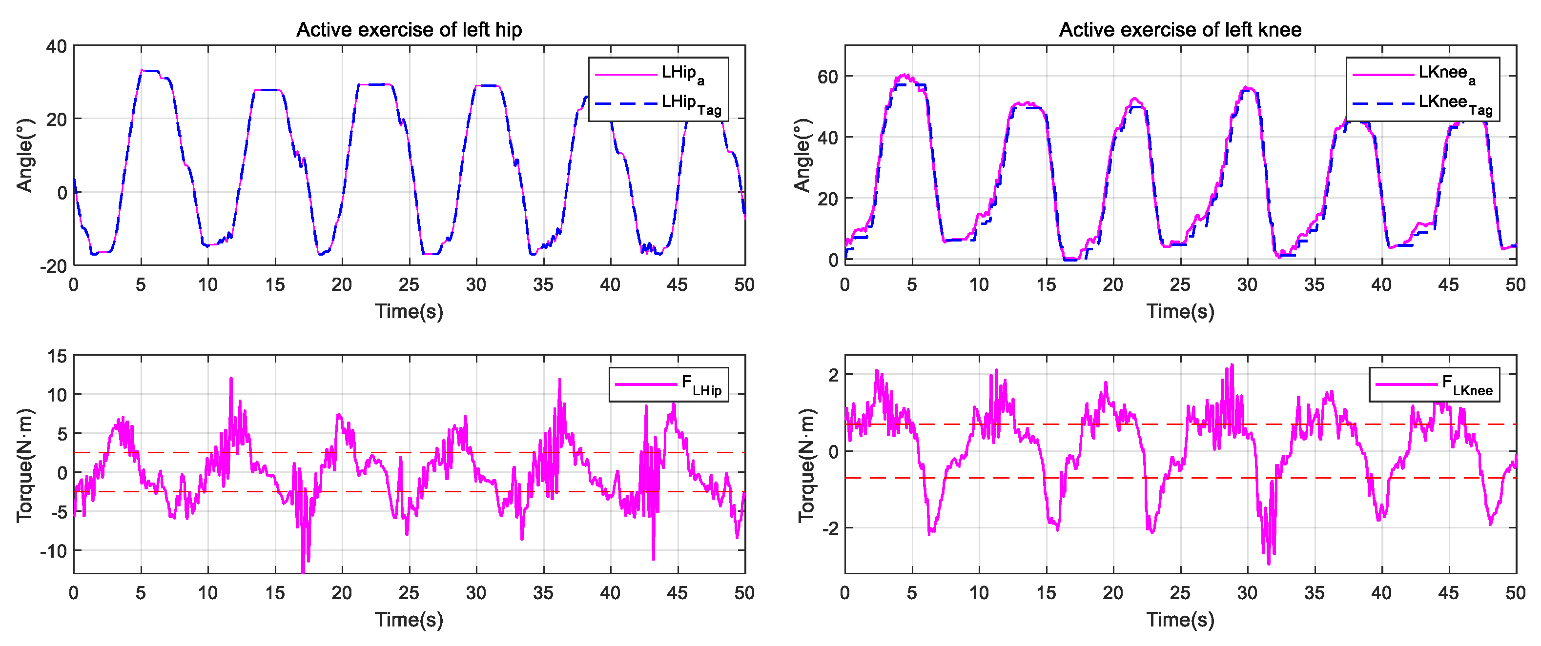
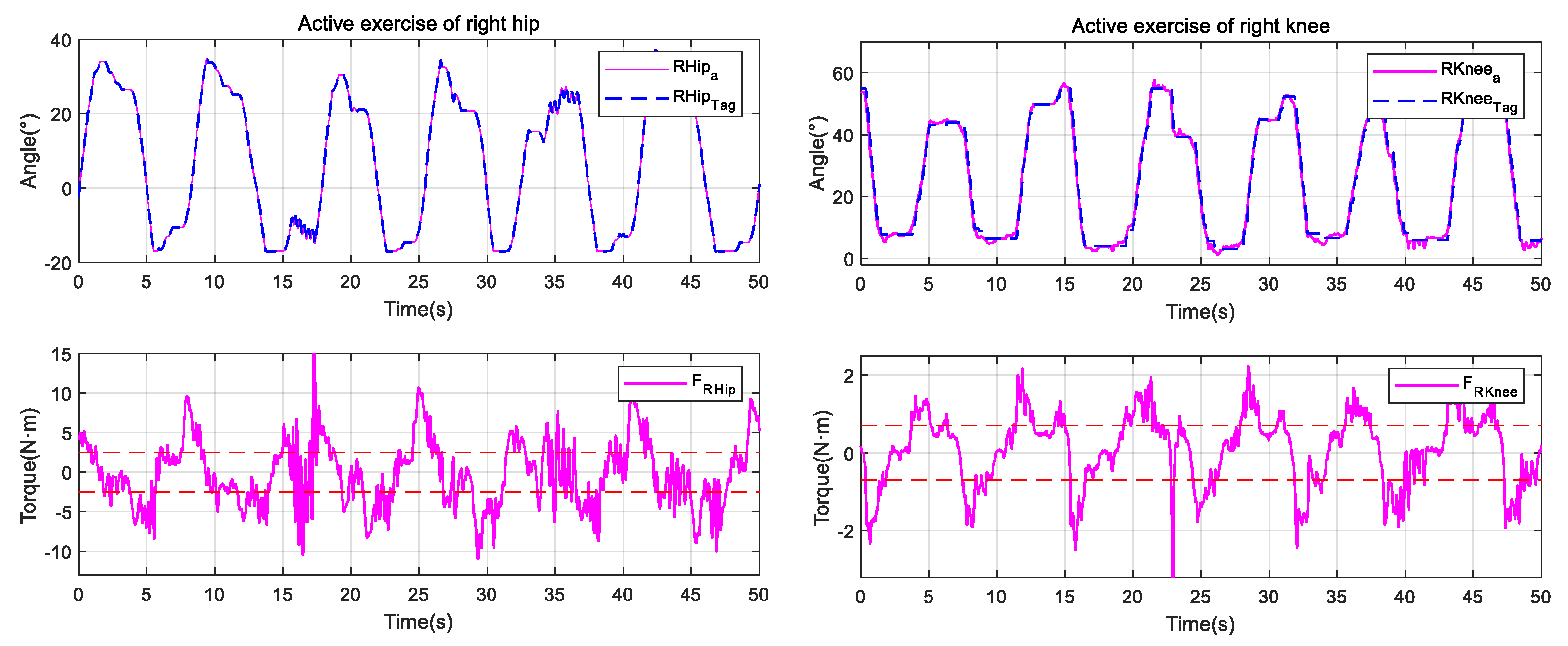
3.3. Active Exercise
The active exercise is suitable for the middle and later stages of the patient’s rehabilitation training. At this time, the patient’s intention of active participation is enhanced, and the patient has a certain ability of lower limb movement. The legs can walk, but the flexibility of the training needs to be ensured. During the active exercise, the human-robot torque is used as the excitation signal, and the output displacement of the motor makes the LLRR follow the movement of the legs, during which, the human-robot interaction torque is small, allowing the patient to perform large-scale movements and avoiding secondary damage caused by excessive interaction torque.
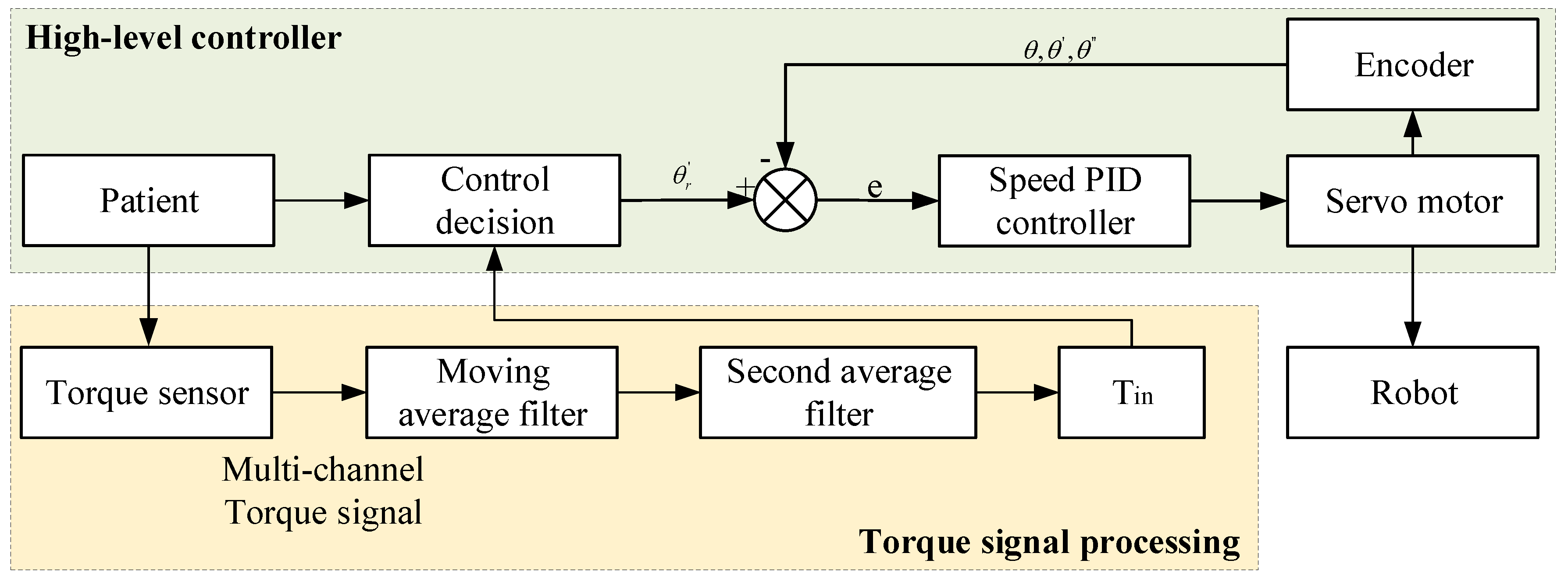
The proposed active exercise strategy includes two main aspects; one is the upper-level decision-making control system, which provides speed gain and position limit for the control strategy, inputs torque information to the controller, and outputs the target speed; The other is torque signal processing by using moving average filter and a second average filter to eliminate jumping points, and then input the torque value after filtering to the upper-level decision-making control system. The flow chart of the active exercise is shown as in
Figure 7, where, the
is the interaction torque after filtering. During the active exercise, we set the training mode to the active exercise in the HRI; The interactive torque between the patient and the LLRR is measured and transmitted to the MCU for filtering operation, which is sent to the upper controller for analysis and processing combining with the gait information; the control system converts the input torque to the desired speed of joint motion, guiding the robot to follow the gait trajectory to follow the patient to complete the gait movement, which means that when the measured interaction torque is zero, the angular velocity becomes zero too, and the LLRR will stay where it is. By setting different coefficient between the interaction torque and the speed, different actual gait trajectories can be obtained under the same torque, so as to match different rehabilitation situations.
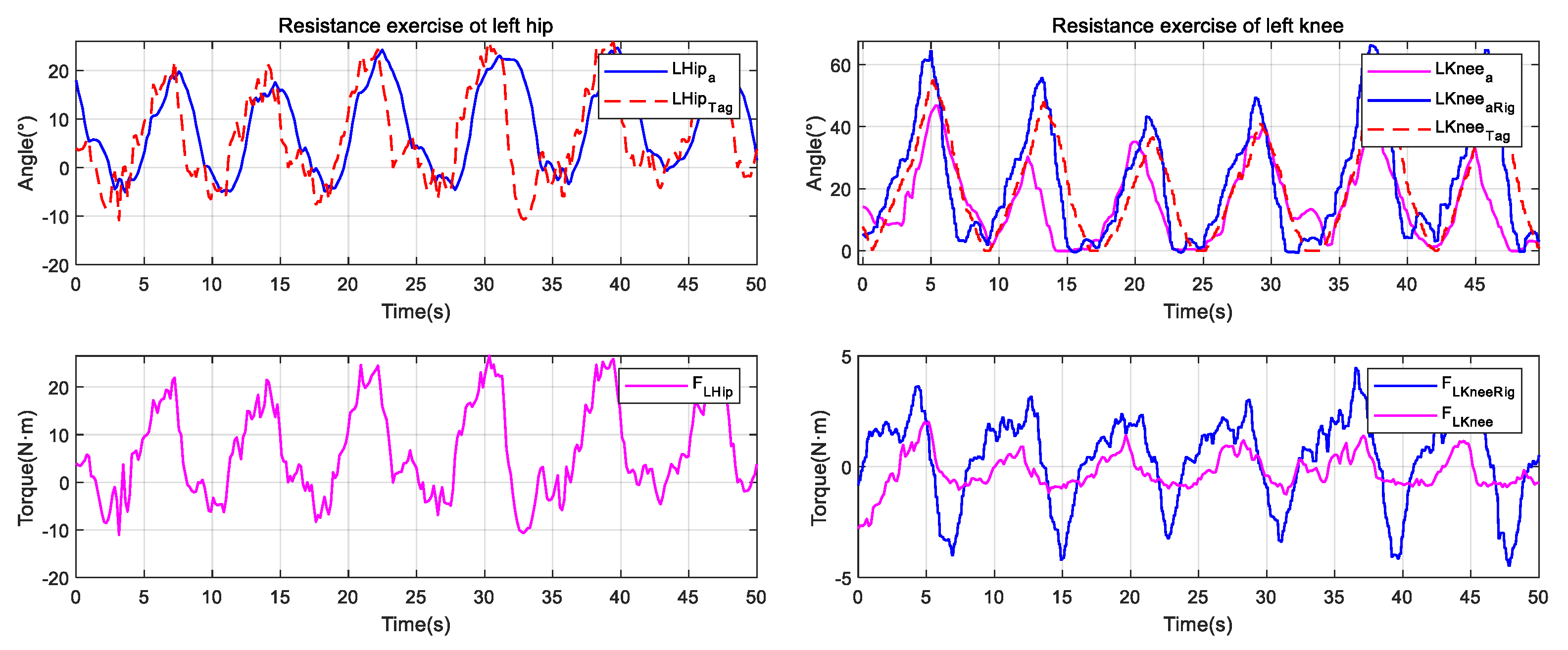
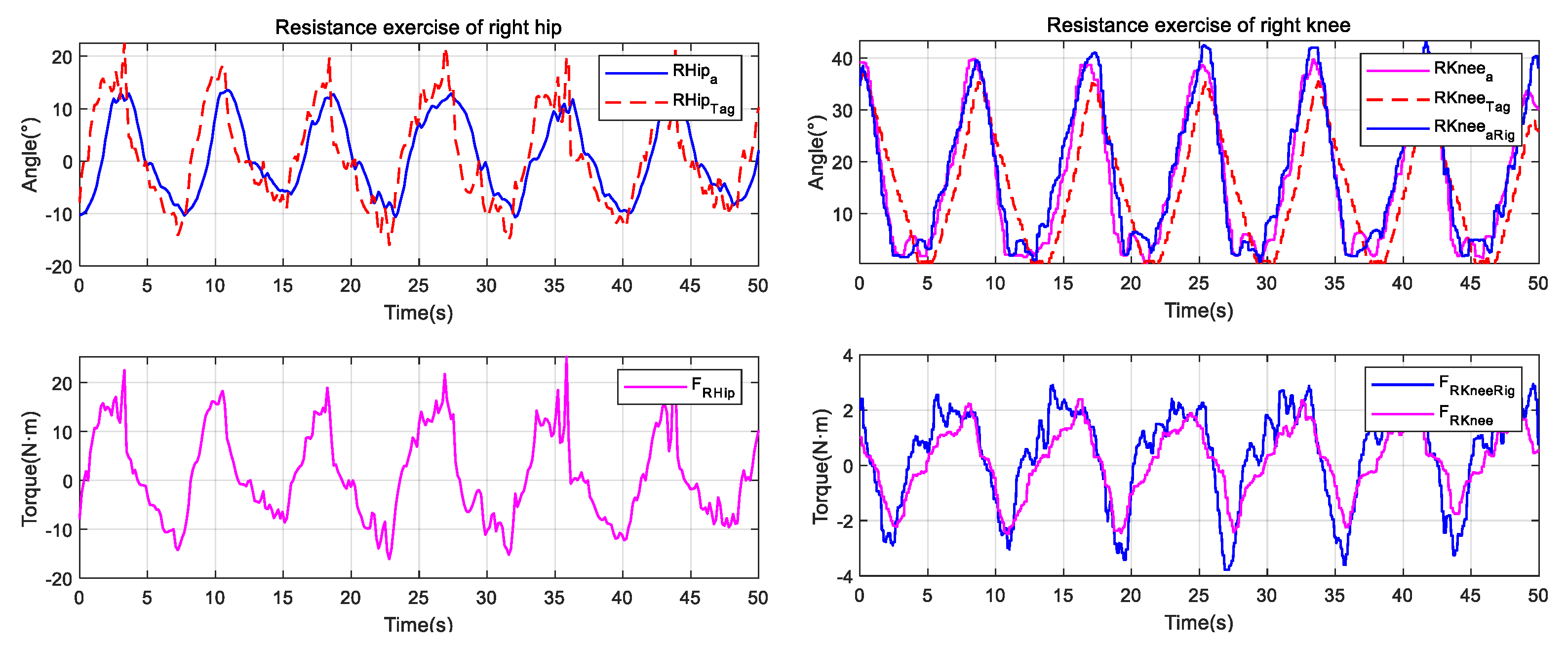
3.4. Resistance Exercise
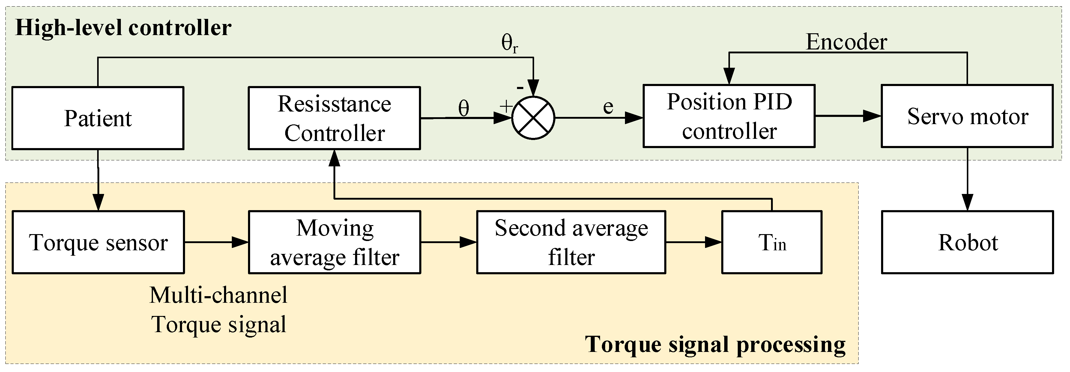
The resistance exercise is suitable for last stages of the patient’s rehabilitation, which can be used to enhance the muscle strength; By resisting the resistance added from the robot, the motivation of rehabilitation training can be further stimulated, and thus increase the lower limb’s muscle strength. For the LLRR, the position-based resistance control strategy is adopted, and the position control loop is corrected using the force signal as feedback. The specific implementation of the resistance exercise is as the follows. The human-robot interaction torque after processing is put into the resistance controller, which is the mapping between the interaction torque and the rotation angle; The resistance controller generates a deflection displacement relative to the initial position, and the deflection displacement depends on the size of the patient’s active torque and the resistance parameter setting, which means that when the interaction torque is zero, the LLRR will return to its initial position. The resistance training control flow chart is shown in
Figure 8.


