Article

Machining Performance for Ultrasonic-Assisted Magnetic Abrasive Finishing of a Titanium Alloy: A Comparison with Magnetic Abrasive Finishing

School of Mechanical Engineering, Dalian Jiaotong University, Dalian 116028, China
*
Author to whom correspondence should be addressed.
Machines 2022, 10(10), 902; https://doi.org/10.3390/machines10100902
Submission received: 31 August 2022 / Revised: 25 September 2022 / Accepted: 5 October 2022 / Published: 6 October 2022
(This article belongs to the Special Issue High Precision Abrasive Machining: Machines, Processes and Systems)

Abstract

:
Titanium alloys are widely used in aerospace, the military industry, electronics, automotive fields, etc., due to their excellent properties such as low density, high strength, high-temperature resistance, and corrosion resistance. Many components need to be finished precisely after being cut in these applications. In order to achieve high-quality and high-efficiency finishing of titanium alloys, ultrasonic-assisted magnetic abrasive finishing (UAMAF) was introduced in this research. The machining performance for UAMAF of a titanium alloy was studied by experimentally comparing UAMAF and magnetic abrasive finishing (MAF). The results show that the cutting force of UAMAF can reach 2 to 4 times that of MAF, and it decreases rapidly with the increase in the machining gap due to the energy loss of ultrasonic impact in the transmission between magnetic abrasives. The surface roughness of UAMAF can reach about Ra 0.075 μm, which is reduced by about 59% compared with MAF. The main wear type of the magnetic abrasive is that the diamond grits fell off the magnetic abrasive in both UAMAF and MAF. The uniform wear of the magnetic abrasive is realized, and the utilization ratio of the magnetic abrasive is obviously improved in UAMAF.

1. Introduction

Titanium alloys, the third-generation metal after steel and aluminum, have been widely used in aerospace, the military industry, electronics, automotive fields, etc., due to its excellent properties such as low density, high strength, high-temperature resistance, and corrosion resistance [1]. Titanium alloys are mainly used for manufacturing complex parts such as blades and integral impellers of jet engines, as well as accurate dies and rotors of turbomolecular pumps. The complex curved surface, which plays a key role, needs finishing precisely after these parts are cut. It is difficult to guarantee the machining precision and surface quality because of the high strength, strong toughness, large viscosity, and small thermal conductivity of titanium alloys, which are a typical difficult-to-cut material [2,3].
In order to achieve the high-quality and high-efficiency finishing of these complex parts of difficult-to-cut alloys, some new technologies for composite finishing with a variety of energy sources have been applied to the finishing of such materials. The machining technology of ultrasonic-assisted magnetic abrasive finishing (UAMAF) is a combination of ultrasonic vibration and magnetic abrasive finishing (MAF), and it can achieve high efficiency, high precision, and high quality in the finishing of difficult-to-cut materials [4]. Therefore, some researchers have devoted themselves to the investigation of UAMAF of difficult-to-cut materials.
The experimental research on UAMAF of high carbon steel with hardness HV730 was carried out by MULIK et al. The results show that the machining mode turns into interrupted cutting due to the effect of ultrasonic vibration. The microscratches are randomly distributed on the surface, which is found by observing the topography of the machined surface. Therefore, the material removal process is the function of microchipping and nanoscratching. The surface roughness of the workpiece can reach Ra 0.022 μm after UAMAF [5,6]. The experiment on UAMAF of the inner surface of a nickel-based alloy tube was carried out by Chen et al. The results show that the surface roughness is decreased from Ra 2.4 μm to Ra 0.31 μm by finishing for 30 min with an ultrasonic amplitude of 19 μm at the vibration frequency of 19 kHz [7]. The experimental research on UAMAF of a titanium alloy was developed by Zhou et al. The results show that the surface residual stress of the workpiece changed from a tensile stress of +280 MPa to a compressive stress of −20 MPa [8]. Çelik et al. carried out the experiment on UAMAF of the white layer of the Ti6Al4V alloy formed by wire-electro-discharge machining, concluding that the white layer thickness could decrease by 89% after UAMAF [9].
In order to further research the machining performance of UAMAF, some researchers carried out a comparative experimental study on UAMAF and MAF. The experiment on UAMAF of stainless steel was developed and compared with MAF by Chen et al. The results show that the removal rate of the workpiece is higher, and the machining efficiency can be increased by about 50% with the help of ultrasonic vibration. Likewise, the surface roughness can be reduced to 0.06 μm, and the surface microtopography is fine and uniform [10]. The passivation experiment on UAMAF of the cutting edge of the cemented carbide cutter was conducted by Qi et al. The results show that the passivation efficiency can be improved by about 26% compared with MAF to obtain the same passivation roundness radius [11]. The comparative experiment on UAMAF and MAF of the taper hole of a titanium alloy was conducted by Jiao et al. The results show that the material removal rate of UAMAF is increased to 1.6 times that of MAF [12]. Guo et al. shows that the material removal ratio of UAMAF is 1.9 times than that of MAF through the comparative experiment on machining the parts of the 30CrMnSi grooves [13]. Anjaneyulu et al. investigated the surface integrity of Hastelloy C-276 after UAMAF and MAF. The results show that the surface roughness after UAMAF can be reduced to Ra 0.096 μm from the initial average roughness of Ra 1.3 μm; however, the surface roughness after MAF only can be reduced to 0.325 μm [14].
The previous studies show that high efficiency and precision machining for difficult-to-cut alloys can be attained by UAMAF. However, the machining performance for UAMAF of titanium alloys should be researched, and the effect mechanism of the ultrasonic vibration in UAMAF should especially be analyzed further through comparative experiments and theoretical analyses.
In this study, a cutting force model for UAMAF of a titanium alloy was established, and a comparative experiment on UAMAF and MAF of a titanium alloy was carried out. Based on the cutting force model and experiment results, the effects of the ultrasonic parameter and machining parameter on cutting force, surface quality, and machining performance of the magnetic abrasive were studied, and the effect mechanism of ultrasonic vibration in UAMAF of a titanium alloy was analyzed.

2. Machining Principle of UAMAF and the Cutting Force Model

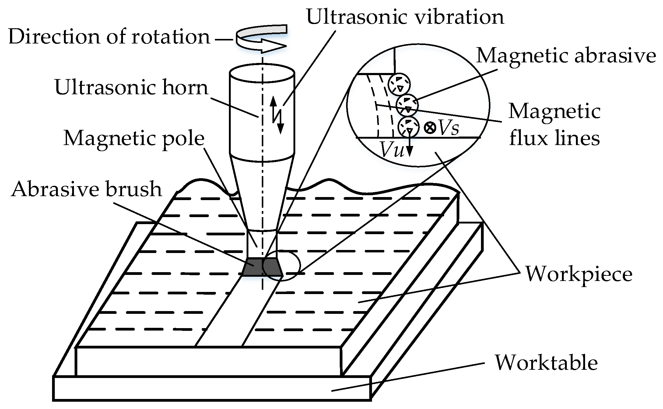
2.1. Machining Principle

UAMAF technology is a composite machining technology realized by applying ultrasonic vibration to a magnetic pole based on the MAF. The applied ultrasonic vibration on the magnetic pole can trigger the vibration of the magnetic abrasive. The machining principle of UAMAF is shown in Figure 1. The magnetic abrasive is pressed on the surface of the workpiece by the magnetic force of the magnetic pole. The workpiece material is removed by cutting the magnetic abrasive at the speed of Vs, which is driven by the rotating motion of the magnetic pole through the magnetic field force, and is also removed through the high-frequency and high-velocity impact of the magnetic abrasive at the speed of Vu, driven by the ultrasonic vibration of the magnetic pole. The depth of the abrasive pressed into the surface layer of the workpiece and the contact length between the abrasive and the workpiece are increased due to the effect of ultrasonic vibration. Therefore, the material removal rate is increased, and the machining efficiency is improved.

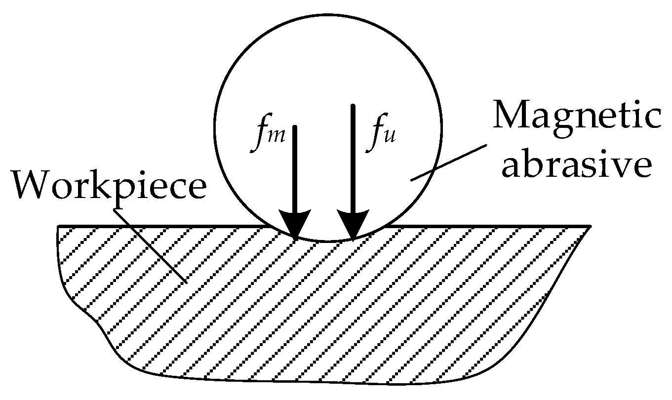
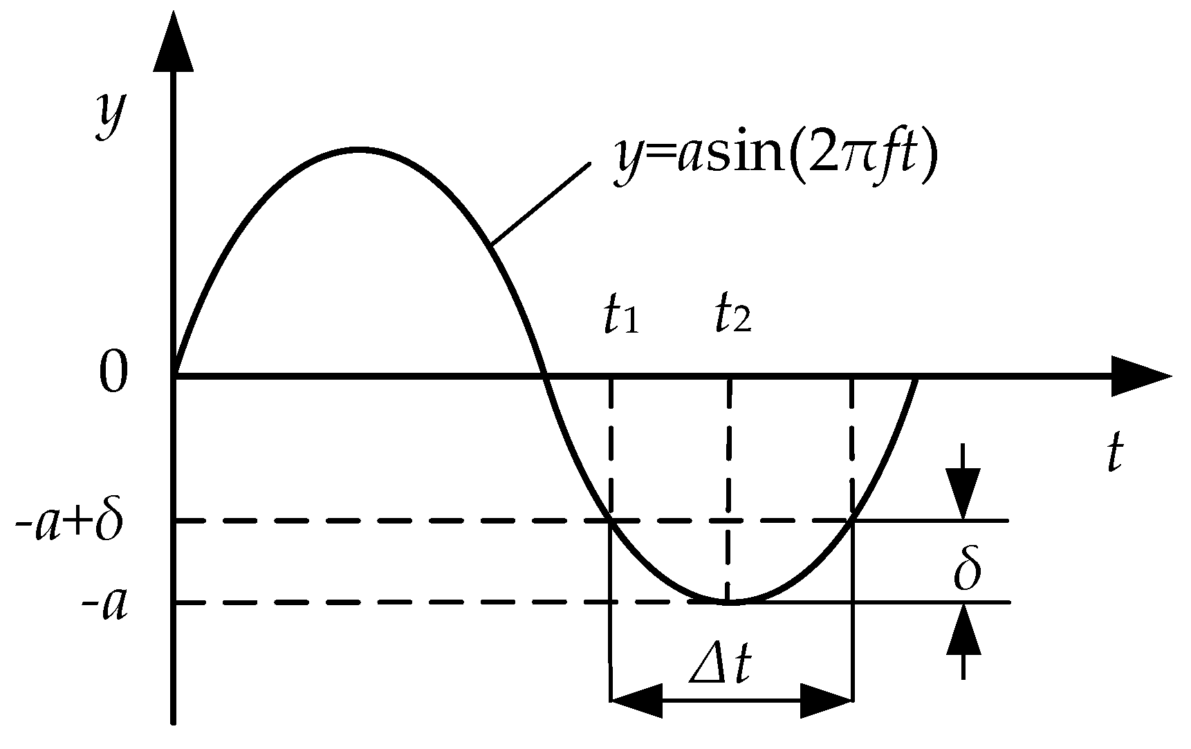
2.2. Modeling of Cutting Force

The cutting force of the magnetic abrasive on the workpiece is mainly composed of the magnetic force and ultrasonic force in UAMAF, and the analysis diagram of the cutting force is shown in Figure 2.
It can be seen from Figure 2 that the relationship among the cutting force f n , magnetic force f m , and ultrasonic force f u of a single magnetic abrasive is as follows:
f n = f m + f u
According to Maxwell’s equations, the cutting pressure P of a magnetic abrasive on a workpiece only under a magnetic field can be expressed as:
P = B 2 2 μ 0 ( 1 1 μ m )
where B is the magnetic induction intensity, μ 0 is the permeability in the vacuum, and μ m is the relative permeability of the magnetic abrasive [15].
The total normal cutting force F M of all the magnetic abrasives under the magnetic field is calculated as:
F M = P A M = B 2 A M 2 μ 0 ( 1 1 μ m )
where A M is the effective contact area between the magnetic abrasive brush and the workpiece.
Therefore, the magnetic force f m of a single magnetic abrasive can be given by:
f m = F M n = B 2 A M 2 n μ 0 ( 1 1 μ m )
where n is the number of the effective magnetic abrasives which actually participate in finishing.
The motion of a single magnetic abrasive under ultrasonic vibration can be described approximately as a harmonic vibration in UAMAF, as shown in Figure 3, in which Δ t is the effective contact time between the magnetic abrasive and the workpiece, and δ is the depth of the magnetic abrasive pressed into the workpiece under ultrasonic vibration.
It can be seen from Figure 3 that the magnetic abrasive is moved from y = ( δ a ) to y = a during the time Δ t / 2 from t 1 to t 2 in an ultrasonic vibration period; thus, the time Δ t can be concluded as follows:
Δ t = 1 π f [ π 2 arcsin ( 1 δ a ) ]
where f is the ultrasonic vibration frequency.
Suppose that the magnetic abrasive cannot be compressed, the impulse of a single magnetic abrasive in an ultrasonic vibration period is derived as [16]:
i m p u l s e = T f u ( t ) d t f c u Δ t
where f u ( t ) is the force acting on the magnetic abrasive under ultrasonic vibration, and f c u is the average contact force between the magnetic abrasive and workpiece under ultrasonic vibration.
The average contact force f c u between the magnetic abrasive and workpiece under ultrasonic vibration can be given by:
f c u = σ s A c u
where σ s is the yield strength of the workpiece material, and A c u is the average area of the magnetic abrasive pressed into the workpiece under ultrasonic vibration.
The impulse of a single abrasive in an ultrasonic vibration period can be expressed as:
i m p l u s e = f u T = f u f
Substituting (8) into (6), the ultrasonic force f u of a single magnetic abrasive on the workpiece is calculated as:
f u = f c u Δ t f
Substituting (5) and (7) into (9), it can be derived as:
f u = σ s A c u 1 π [ π 2 arcsin ( 1 δ a ) ]
Substituting (4) and (10) into (1), it can be concluded as follows:
f n = B 2 A M 2 n μ 0 ( 1 1 μ m ) + σ s A c u 1 π [ π 2 arcsin ( 1 δ a ) ]
Therefore, the total cutting force F n of the magnetic abrasive on the workpiece in UAMAF can be expressed as:
F n = B 2 A M 2 μ 0 ( 1 1 μ m ) + σ s A c u n π [ π 2 arcsin ( 1 δ a ) ]

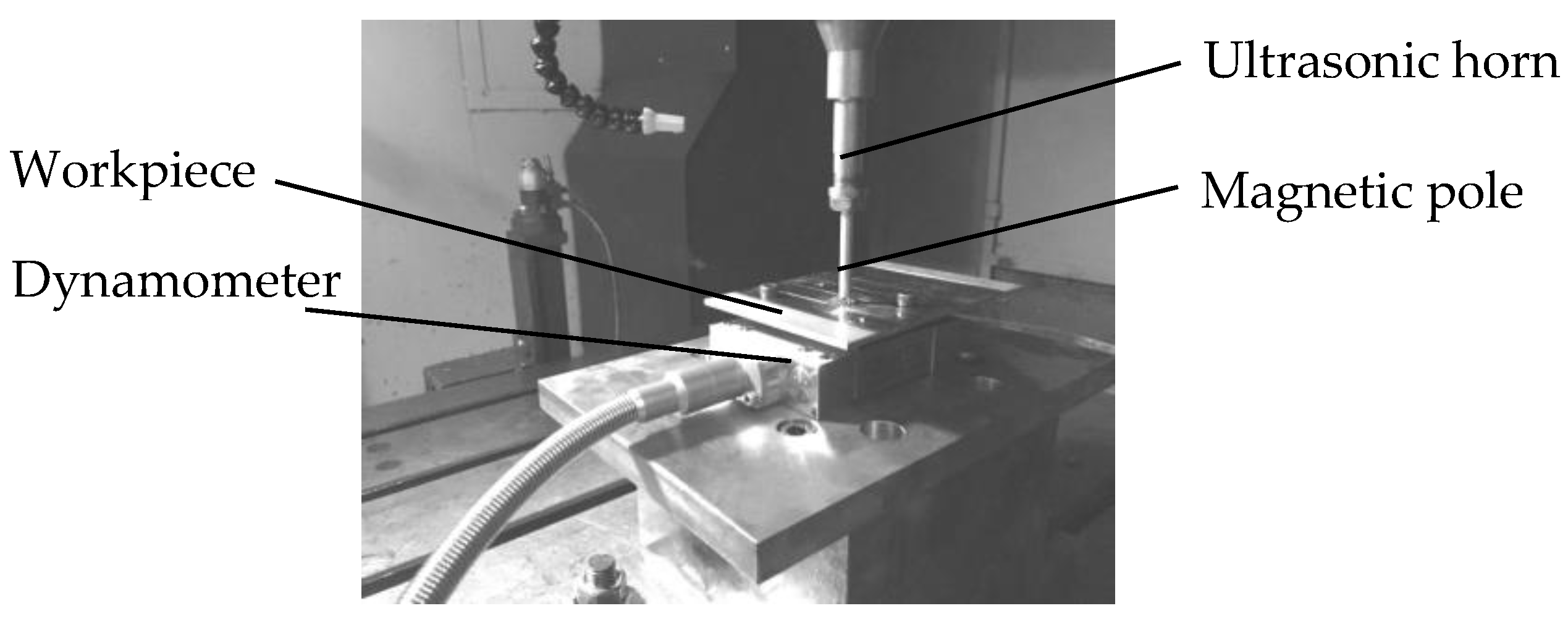
3. Experiment Conditions

The experiment setup was built by assembling an ultrasonic vibration system into a 3-axis CNC machine tool, as shown in Figure 4. The resonance frequency of the ultrasonic vibration system is 21.91 kHz, and the ultrasonic amplitude can be adjusted continuously from 5 μm to 15 μm. The workpiece material is the TC4 titanium alloy, and the mechanical properties of the TC4 are shown in Table 1. The magnetic pole is an N38 neodymium magnet with a diameter of 6mm in the experiment. The cooling lubricant is Castrol 9930 water-soluble cutting fluid with a concentration of 8%. The magnetic abrasive is prepared with a chemical-composited coating, and the average diameter is about 300 μm. The surface topography of the prepared magnetic abrasive is shown in Figure 5. By combing findings from previous research with the performance of the experiment setup and the preliminary exploratory experiment, the suitable machining parameters were found and listed in Table 2, in which the ultrasonic amplitude of 0 μm represents MAF. A group of machining parameters with the spindle speed of 1000 r/min, a feed rate of 15 mm, and a machining gap of 1.5 mm, which has an excellent performance in MAF, was selected to be used in the comparative experiment of surface roughness and machining performance of the magnetic abrasive.
A Kistler 9119AA2 piezoelectric dynamometer was used to measure the cutting force in UAMAF and MAF. The surface roughness after milling, UAMAF, and MAF was measured by a Form Talysurf PGI 840 surface profiler, and the cut-off length for the measuring was selected according to ISO 468:1982. Each set of cutting force and surface roughness was measured three times, and the average was employed. The surface topography of the magnetic abrasive was observed with a JSM 6360LV scanning electron microscope (SEM). A Keyence VHX-600E super-depth-of-field microscope was used to monitor the surface micrograph of the workpiece.

4. Results and Discussion

4.1. Cutting Force

Firstly, the dynamometer and ultrasonic power supply are turned on, and then, the magnetic pole is lowered to the location at the machining gap of 1.5 mm. The ultrasonic power supply is turned off after feeding for about 10 s, and then, the magnetic pole continues to feed for about 10 s. After that, the magnetic pole is lifted up, and the dynamometer is closed. The measured force curve is shown in Figure 6, and it is divided into three sections. The first section is a cut-in section from the beginning of the experiment to the point when the magnetic pole drops to the machining gap of 1.5 mm. The second section is the machining period of UAMAF, and the third is that of MAF. The average forces of the stable part of the second and third sections are taken to characterize cutting forces in the experiment of UAMAF and MAF, respectively. It can be seen from Figure 6 that there is a sudden drop in the cutting force from the machining period of UAMAF to that of MAF. Equation (12) shows that the cutting force in UAMAF consists of the ultrasonic force and magnetic force. The sudden drop is due to the disappearance of the ultrasonic force in the machining period of MAF.

4.1.1. Effect of Ultrasonic Amplitude on Cutting Force

The spindle speed, feed rate, and machining gap are 1000 r/min, 15 mm/min, and 1.5 mm, respectively, and the other machining parameters are shown in Table 2. The cutting forces of UAMAF with different ultrasonic amplitudes and of MAF are measured, and the results are shown in Figure 7. It shows that the cutting force of UAMAF increases approximately linearly with the increase in ultrasonic amplitude, and the cutting force of UAMAF is 2 to 4 times greater than that of MAF in the range of the ultrasonic amplitude of 6 μm to 14 μm.
From Equation (1), it can be seen that the cutting force of a single magnetic abrasive on the workpiece consists of the magnetic force and ultrasonic force in UAMAF, and the magnetic force remains unchanged in the machining. From Equation (8), it can be found that the ultrasonic force is increased linearly with the increase in ultrasonic amplitude, because the ultrasonic impulse is increased with the increase in ultrasonic amplitude while the ultrasonic frequency remains unchanged. Therefore, the cutting force is increased linearly with the increase in ultrasonic amplitude in UAMAF. From Equation (12), it can be seen that the cutting force is greatly increased in UAMAF compared with MAF, due to the effect of ultrasonic vibration.

4.1.2. Effect of Machining Gap on Cutting Force

The spindle speed, feed rate, and ultrasonic amplitude are 1000 r/min, 15 mm/min, and 10 μm, respectively, and the other machining parameters are shown in Table 2. The cutting forces of UAMAF and MAF with different machining gaps are measured, and the results are shown in Figure 8.
From Figure 8, it can be seen that both the cutting force and ultrasonic force decrease rapidly with the increase in the machining gap in UAMAF. Because magnetic abrasives are layered uniformly along the magnetic flux lines in the machining gap, magnetic abrasives on the top layer are impacted by the ultrasonic vibration of the end face of the magnetic pole, and the ultrasonic vibration energy is transferred layer by layer, this leads to the magnetic abrasives in the lowest layer acting on the workpiece in UAMAF. The energy loss in these collisions can be characterized by an energy transfer coefficient η , which can be expressed as follows:
η = F U i / F U i + 1
where F U i is the ultrasonic force between magnetic abrasives of the ith layer and the front in the machining gap.
From Figure 8, it also can be seen that the energy transfer coefficient of ultrasonic impact is about 60% in UAMAF, and thus, the ultrasonic force decreases rapidly in proportion with the increase in the machining gap. At the same time, the magnetic field intensity at the location of the magnetic abrasive is decreased gradually with the increase in the machining gap. From Equation (3), the magnetic force of the magnetic abrasive that acted on the workpiece is also decreased gradually with the increase in the machining gap. Therefore, the total cutting force, which is formed by both the ultrasonic force and magnetic force, is decreased rapidly with the increase in the machining gap in UAMAF.

4.1.3. Effect of Feed Rate on Cutting Force

The spindle speed, machining gap, and ultrasonic amplitude are 1000 r/min, 1.5 mm, and 10 μm, respectively, and the other machining parameters are shown in Table 2. The cutting forces of UAMAF and MAF with different feed rates are measured, and the results are shown in Figure 9. It shows that the cutting force of UAMAF is 2 to 4 times greater than that of MAF in the range of the feed rate from 5 mm/min to 20 mm/min. The cutting forces of two machining methods are increased with the increase in feed rate, but the increased speed of the cutting force of UAMAF is faster.
Because the initial surface of the workpiece is obtained by milling, which causes an obvious machining texture, the height difference between the wave crest and trough is large. The main removal material is the wave crest in the force measurement process of UAMAF and MAF, owing to the vertex effect in machining. Therefore, the faster the feed rate is, the less the wave crest removal is. Therefore, the difference between the wave crest and trough is greater, the surface area of the workpiece is larger, and there are more effective abrasives that are involved in machining, as the feed rate is increased gradually in UAMAF and MAF. From Equation (12), the cutting force is increased with the increase in the feed rate in UAMAF and MAF. At the same time, due to the effect of ultrasonic vibration, the cutting force and material removal efficiency are greater, the wave crest removal is faster, the difference between the wave crest and trough of the machining surface is larger, and the surface area of the workpiece and the number of effective magnetic abrasives involved in machining are decreased faster in UAMAF. Therefore, the cutting force of UAMAF is increased relatively faster than that of MAF with the increase in feed rate.

4.1.4. Effect of Spindle Speed on Cutting Force

The feed rate, machining gap, and ultrasonic amplitude are 15 mm/min, 1.5 mm, and 10 μm, respectively, and the other machining parameters are shown in Table 2. The cutting forces of UAMAF and MAF with different spindle speeds are measured, and the results are shown in Figure 10. It shows that the cutting forces of the two machining methods are decreased linearly with the increase in spindle speed in the range of 800 r/min to 1400 r/min.
The reason for this phenomenon is that the amount of magnetic abrasives that are thrown out is increased gradually as the spindle speed increases, due to the increase in centrifugal force during machining. As a result, the number of magnetic abrasives participating in machining is decreased. From Equation (12), the cutting force is proportional to the number of magnetic abrasives in both UAMAF and MAF. Therefore, the cutting forces of both machining methods are reduced gradually with the increase in spindle speed.

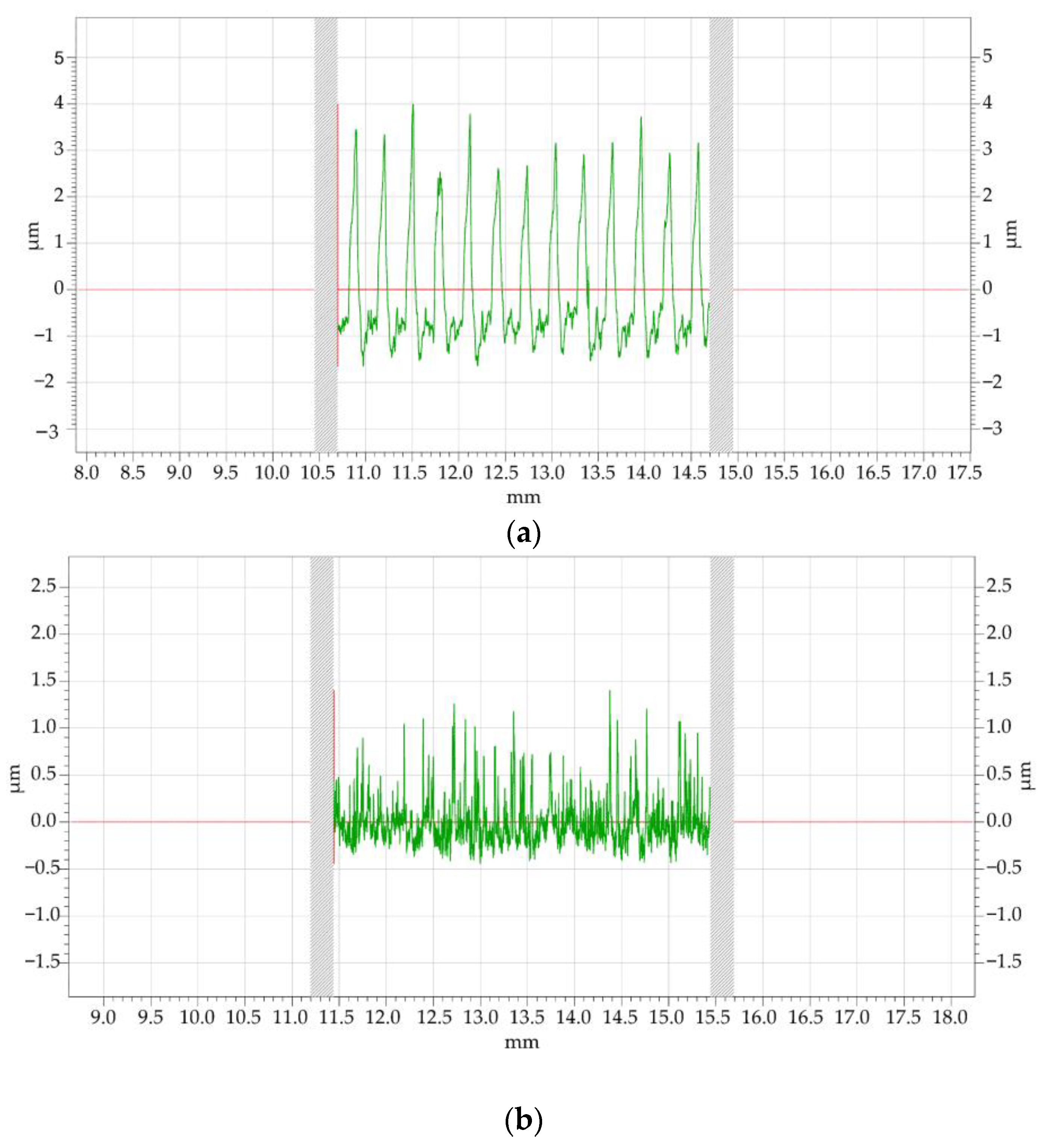
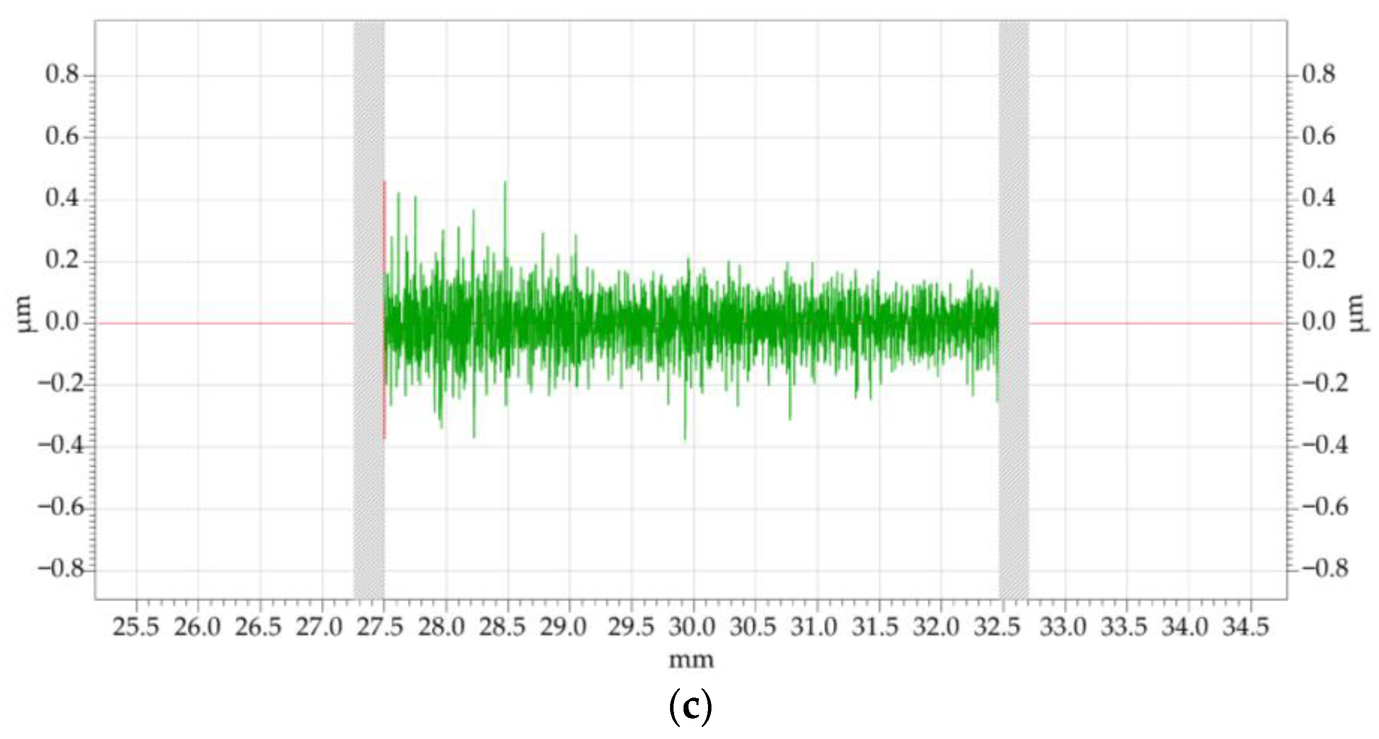
4.2. Surface Roughness

The surface roughness (Ra) of the workpiece after UAMAF and MAF was measured every 5 min. The ultrasonic amplitude in UAMAF was set to 10 μm. The variation curve of surface roughness with the machining time is shown in Figure 11, and the surface roughness curves and the surface micrographs after milling, MAF, and UAMAF are shown in Figure 12 and Figure 13, respectively.
As can be seen from Figure 11, the surface roughness of the workpiece is decreased gradually with the increase in machining time in MAF. After 40 min of MAF, the surface roughness of the workpiece is decreased from Ra 1.1 μm to Ra 0.187 μm. It can be seen from Figure 12b that there are obvious scratches on the surface after MAF. The surface roughness is decreased rapidly with the increase in machining time at the beginning of machining in UAMAF. After 10 min of UAMAF, the surface roughness of the workpiece can reach Ra 0.189 μm, and then after 5 min, it can reach Ra 0.1μm. After another 25 min, the surface roughness decreases slowly with the increase in machining time, and finally, can reach Ra 0.075 μm. It can be seen from Figure 12c that the surface topography is evenly distributed without obvious scratches after UAMAF. These indicate that the limit capacity of surface roughness that can be processed by this group of machining parameters has been approached after UAMAF for 15 min. It also can be seen from the comparative analysis of the variation curve of surface roughness with the machining time in UAMAF and MAF that the surface roughness of UAMAF after 10 min is basically the same as that of MAF after 40 min. To evaluate by using the machining time for achieving this surface roughness, the machining time can be shortened to about one quarter, and the machining efficiency in UAMAF can be increased by about four times, compared with MAF. To evaluate by using the surface roughness of finishing after 40 min, the surface roughness can be reduced by 59% in UAMAF, as compared with MAF.
From Figure 12a and Figure 13a, there are a large number of homogeneously distributed crests with a height of about 3μm and troughs with a depth of about 1μm on the surface of the titanium alloy after milling. From Figure 12b,c and Figure 13b,c, it can be seen that the crests and troughs generated by milling on the surface of the titanium alloy are removed after UAMAF and MAF, and a smoother surface is obtained. The crests are removed, firstly, in both UAMAF and MAF. The difference in the height between the wave crest and trough becomes smaller and smaller with the increase in machining time. When a magnetic abrasive is allowed to cut into the groove between the two adjacent wave crests, the magnetic abrasive can cut the whole surface of the workpiece. Therefore, both UAMAF and MAF have the vertex effect. The surface roughness is decreased rapidly at the beginning of machining, then decreases more and more slowly, and finally, remains unchanged basically with the increase in machining time in UAMAF. Because of the increase in cutting force, the material removal rate of UAMAF is larger than that of MAF. It can realize the rapid removal of the wave crest and trough on the surface of the titanium alloy, and cause the rapid reduction of the surface roughness. Due to the effect of ultrasonic vibration, the motion direction of the magnetic abrasive is more random and the motion trajectory of the magnetic abrasive is more complex in UAMAF. The complex trajectory obtains a smoother surface more easily because of the superposition action of several magnetic abrasives. At the same time, due to the high-frequency and high-acceleration impact of ultrasonic vibration, the additional ultrasonic shot peening can make the material of the wave crest of the workpiece surface plastically flow into the wave trough and fill it. Therefore, the lower surface roughness can be obtained more easily in UAMAF than in MAF.

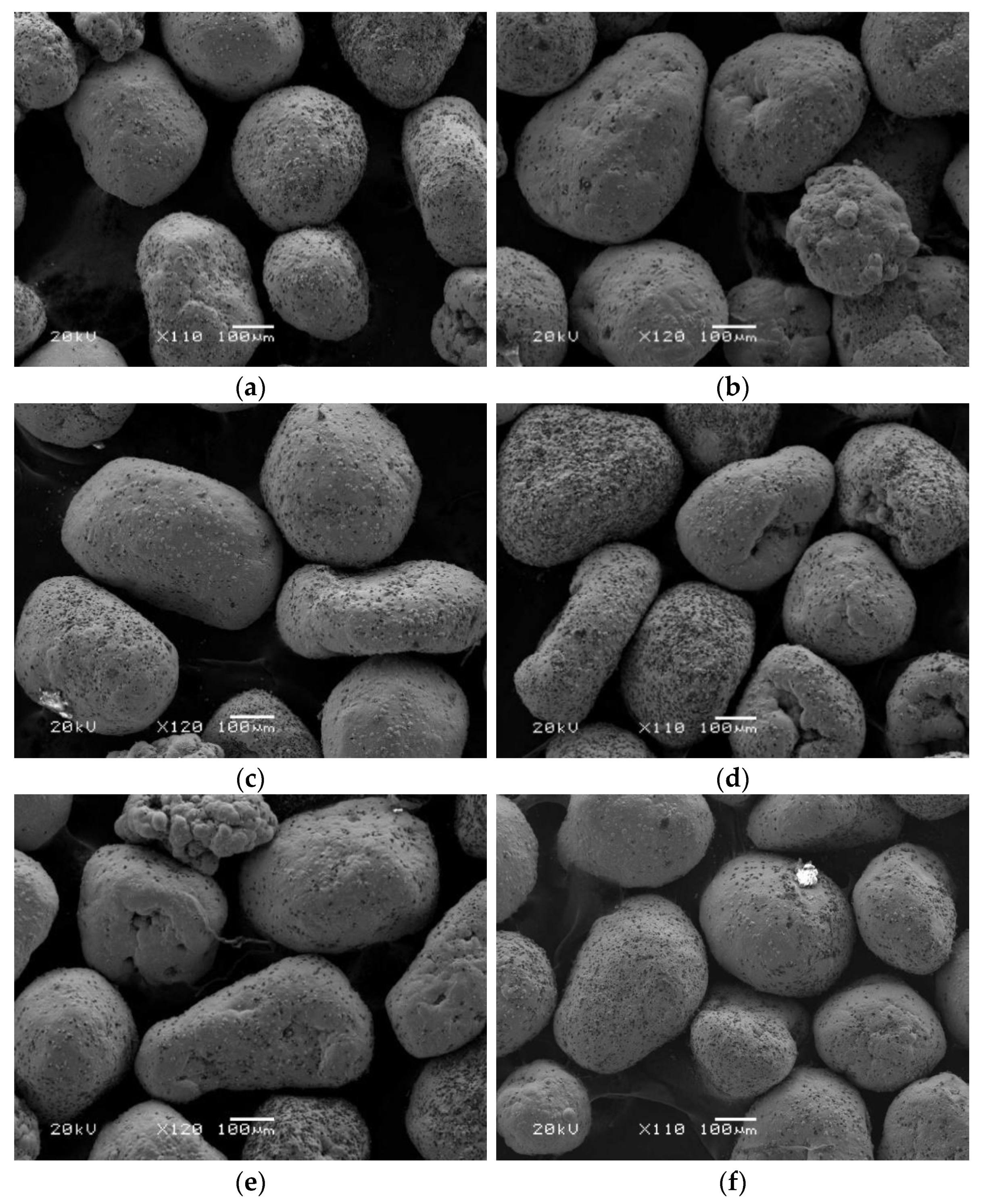
4.3. Machining Performance of Magnetic Abrasive

The experiment on UAMAF and MAF of a titanium alloy was carried out with two groups of magnetic abrasives that have the same initial state. The ultrasonic amplitude in UAMAF was set to 10 μm. The total machining time of each finishing method was 30 min, the magnetic abrasives were randomly sampled every 10 min, and the surface topography of magnetic abrasives was observed by SEM. The results are shown in Figure 14.
From Figure 14, it can be seen that the amount of diamond grits on the surface of the magnetic abrasive decreased gradually with the increase in machining time, and the main wear type of the magnetic abrasive was found to be that the diamond grits fell off from the magnetic abrasive in both UAMAF and MAF. By comparing the results of the two finishing methods, it can be found that the reduction rate of diamond grits is relatively faster in UAMAF, but the distribution of diamond grits is relatively uniform after UAMAF. On the other hand, the distribution of diamond grits is relatively concentrated, with some of the magnetic abrasives having more diamond grits while others have less after MAF.
From Equations (7) and (12) it was found that, because of the effect of ultrasonic vibration, the indentation depth of the magnetic abrasive and cutting force are greater, and diamond grits on the surface of the magnetic abrasive fall off more easily in UAMAF than in MAF. At the same time, due to the effect of ultrasonic vibration, the spatial position in the machining gap and the attitude of the magnetic abrasive are more easily changed in UAMAF. Therefore, the probability of all magnetic abrasives in the machining gap and diamond grits on the magnetic abrasive directly participating in machining is increased greatly, the uniform wear of the magnetic abrasive is realized, and the utilization ratio of the magnetic abrasive is improved greatly. However, the magnetic abrasive only rotates and feeds in MAF. The change in the spatial position in the machining gap and attitude of the magnetic abrasive is an accidental process. Therefore, the wear of the magnetic abrasive is more concentrated, and the utilization rate is relatively lower.

5. Conclusions

In this research, the cutting force, surface roughness, and magnetic abrasive machining performance of UAMAF of a titanium alloy were studied through the comparative experiment of UAMAF and MAF, and the effect mechanism of ultrasonic vibration in UAMAF was also researched. The main conclusions are summarized as follows:
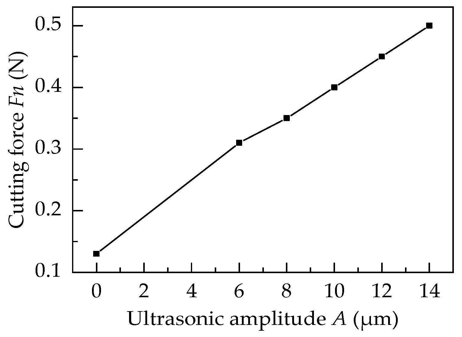
  • Because of the effect of ultrasonic vibration, the cutting force of UAMAF is increased greatly, and is 2 to 4 times greater than that of MAF in the range of the ultrasonic amplitude of 6μm to 14 μm. Moreover, the cutting force of UAMAF is increased approximately linearly with the increase in ultrasonic amplitude.
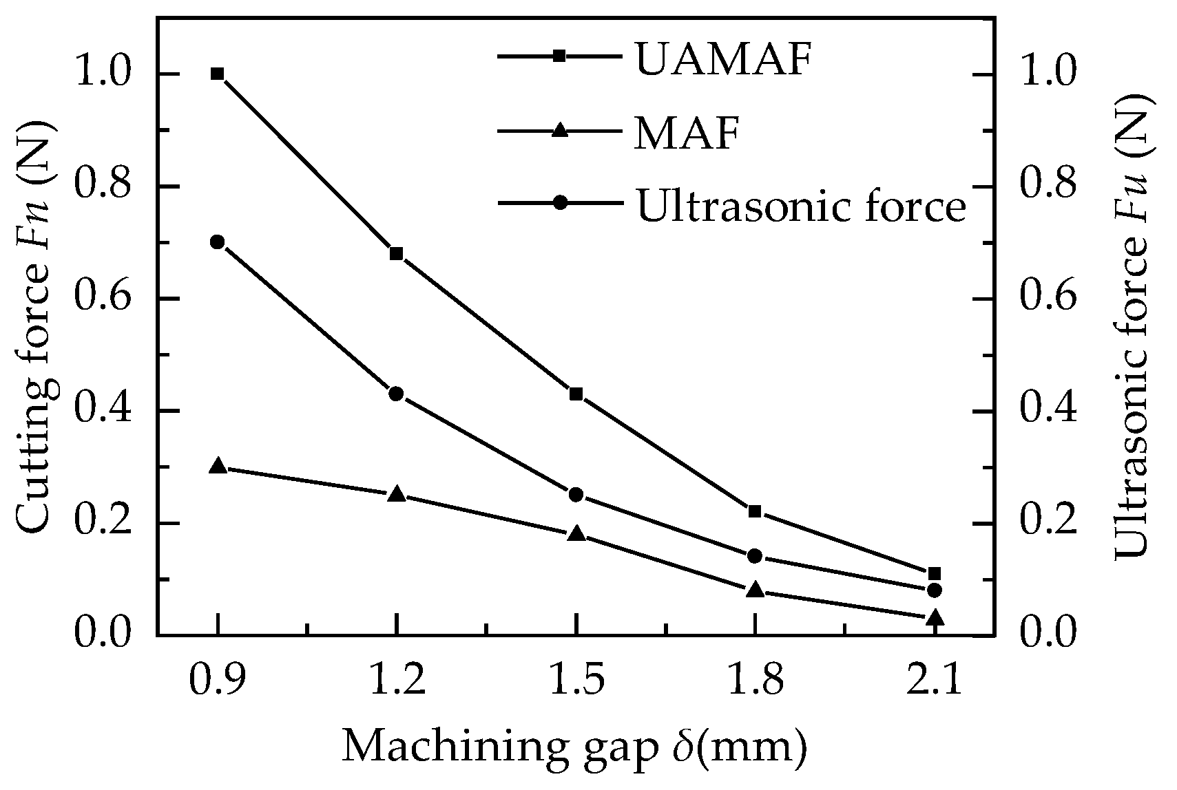
  • The cutting force is decreased rapidly with the increase in the machining gap, due to the energy loss of ultrasonic vibration transmission between the end face of the magnetic pole and the magnetic abrasive, and between magnetic abrasives, and the ultrasonic force is decreased by about 60% in every layer in UAMAF.
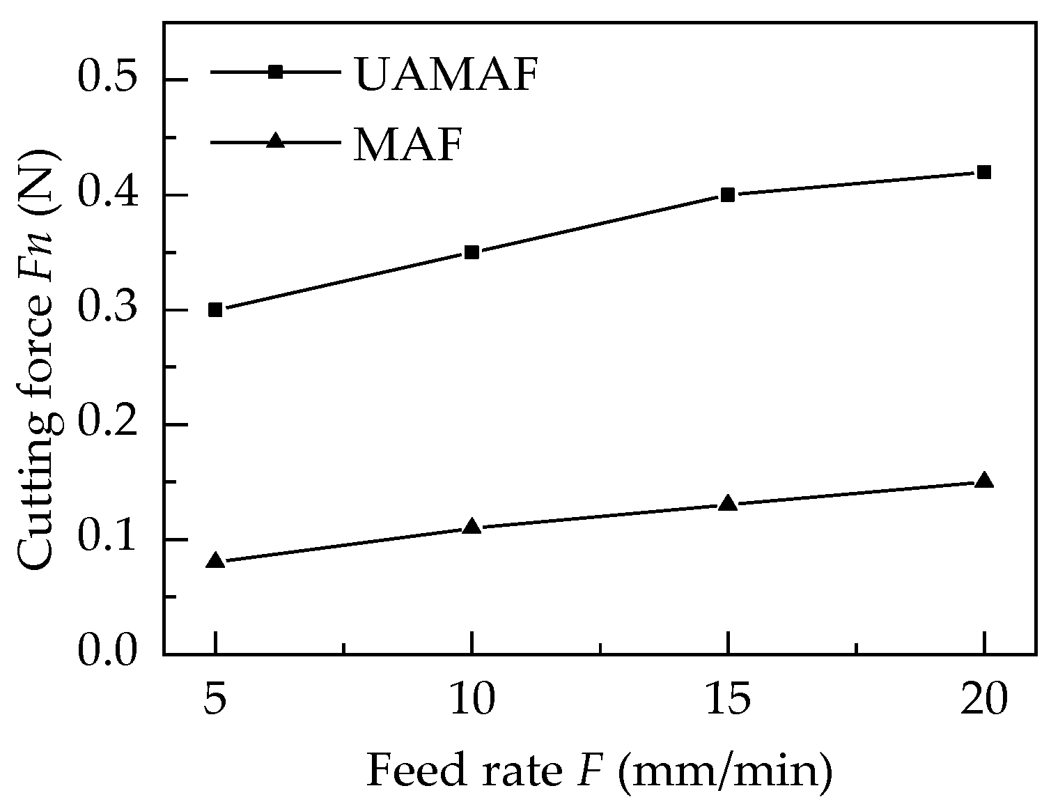
  • The wave crest removal is lower, the surface area of the workpiece is larger, and there are more effective abrasives involved in machining as the feed rate is increased gradually; thus, the cutting force is increased with the increase in the feed rate in UAMAF and MAF. At the same time, due to the effect of ultrasonic vibration, the cutting force and material removal efficiency are greater, and therefore, the cutting force of UAMAF is increased faster than that of MAF relative to the feed rate.
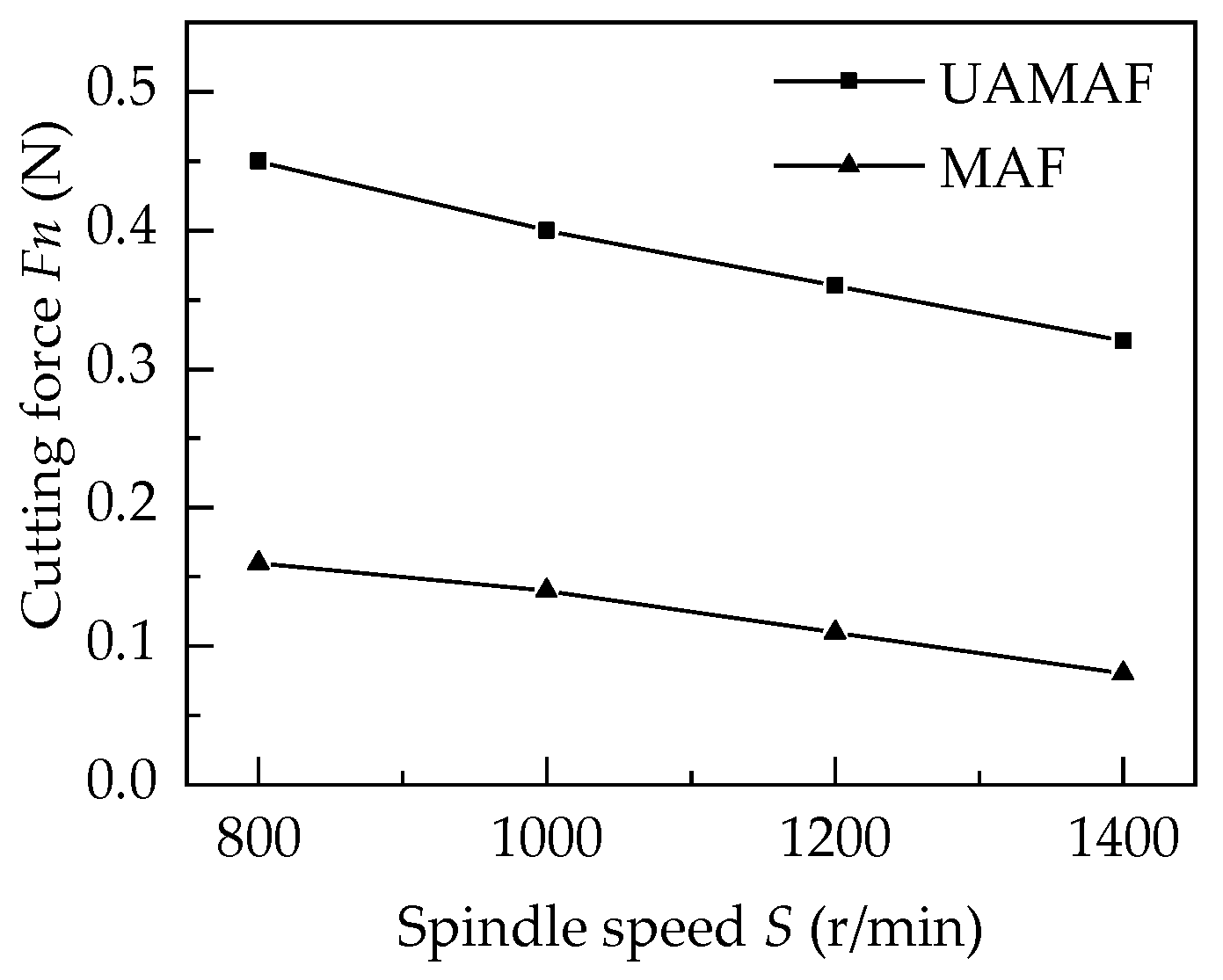
  • The amount of magnetic abrasives that are thrown out is increased gradually as the spindle speed increases, due to the increase in centrifugal force during machining. As a result, the number of magnetic abrasives participating in machining is decreased, and the cutting force of UAMAF and MAF is reduced gradually with the increase in spindle speed.
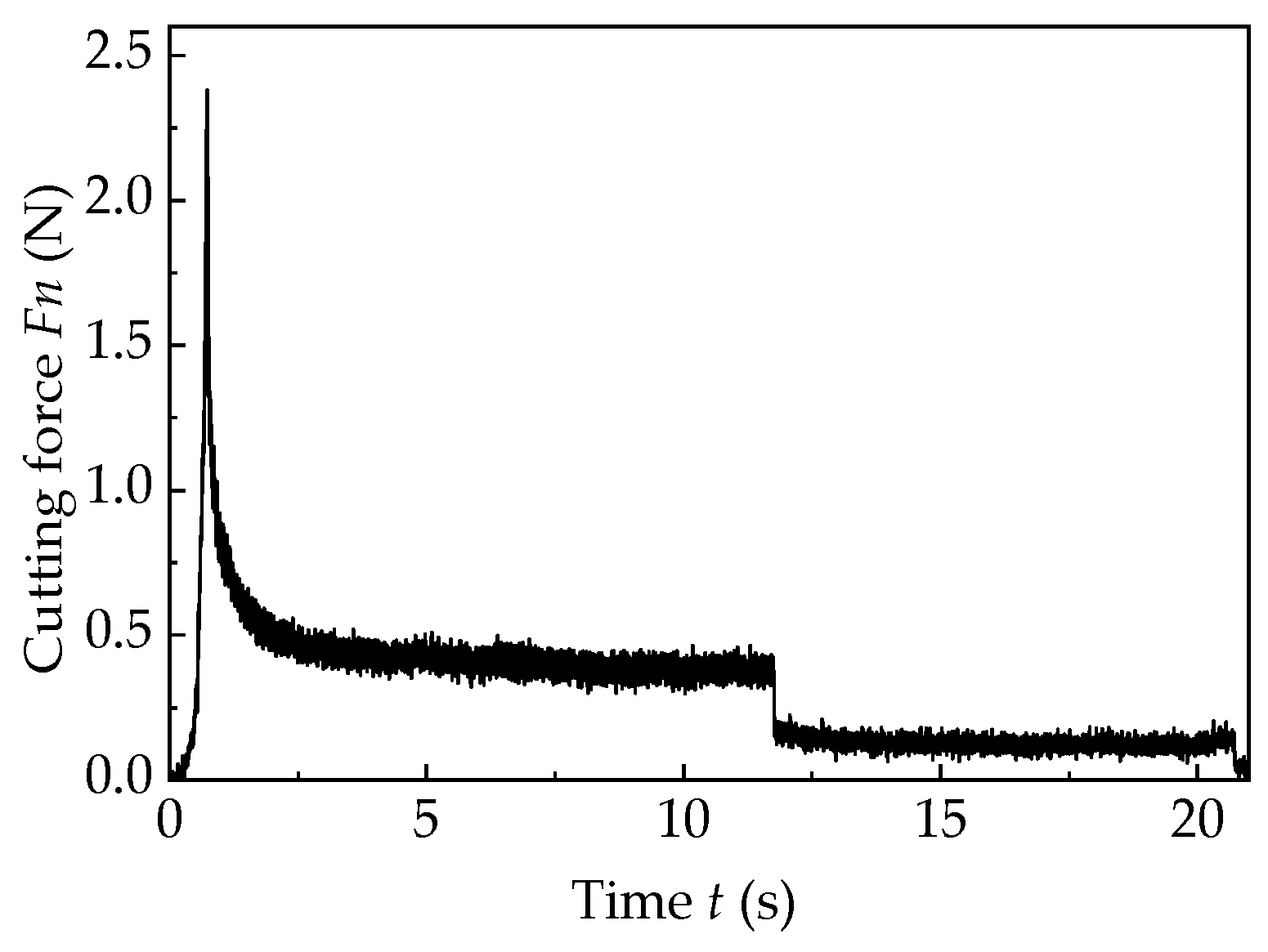
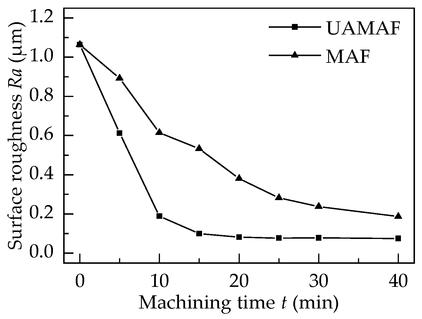
  • Due to the vertex effect of UAMAF, the surface roughness decreased rapidly at the beginning of machining, then decreased more and more slowly, and finally, remained basically unchanged with the increase in machining time.
  • Because of the increase in cutting force, the material removal rate of UAMAF is greater than that of MAF. It can realize the rapid removal of the wave crest on the surface of the titanium alloy and the rapid reduction of the surface roughness. Therefore, the machining efficiency of UAMAF can be increased by about four times, compared with MAF.
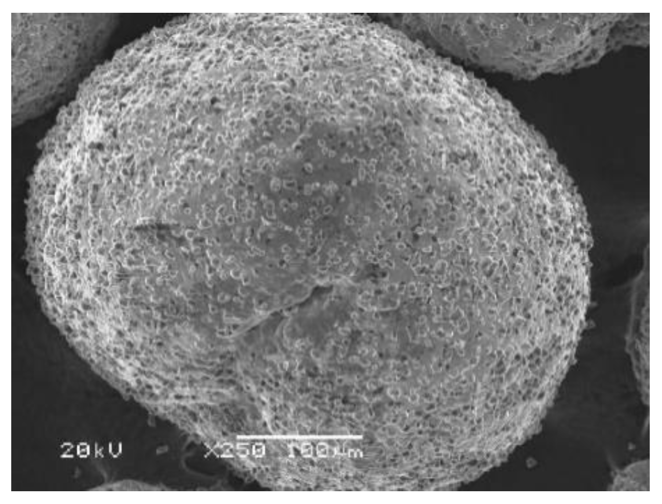
  • The amount of diamond grits on the surface of the magnetic abrasive is decreased gradually with the increase in machining time, and the main wear type of the magnetic abrasive is that the diamond grits fell off from the magnetic abrasive in both UAMAF and MAF.
  • Due to the effect of ultrasonic vibration, the spatial position in the machining gap and the attitude of the magnetic abrasive are more easily changed in UAMAF. Therefore, the probability of all magnetic abrasives in the machining gap and diamond grits on the magnetic abrasive directly participating in machining is increased greatly, the uniform wear of the magnetic abrasive is realized, and the utilization ratio of the magnetic abrasive is improved greatly.

Author Contributions

Conceptualization, F.M. and S.Z.; methodology, F.M. and S.Z.; experimental design, Y.L.; experimental operation, Z.W.; theoretical modeling and analysis, Z.S. and F.M.; data curation, Z.W. and Y.L.; writing—original draft preparation, F.M.; writing—review and editing, S.Z. and Z.S.; project administration, F.M. and S.Z.; funding acquisition, F.M. and S.Z. All authors have read and agreed to the published version of the manuscript.

Funding

This research was funded by the National Natural Science Foundation of China, (Grant No. 51505057 and 52075066), the Scientific Research Project of the Education Department of Liaoning Province (JDL2020015), and the Natural Science Foundation of Liaoning Province (2021-MS-295).

Institutional Review Board Statement

Not applicable.

Informed Consent Statement

Not applicable.

Data Availability Statement

The data presented in this study are available on request from the corresponding author.

Conflicts of Interest

The authors declare no conflict of interest.

References

  1. Liu, W.Y.; Lin, Y.H.; Chen, Y.H.; Shi, T.H.; Singh, H. The effect of different heat treatments on microstructure and mechanical properties of Ti6Al4V titanium alloy. Rare Met. Mater. Eng. 2017, 46, 634–639. [Google Scholar]
  2. Basak, A.K.; Yuan, C.G.; Prakash, C.; Pramanik, A.; Shankar, S. Drilling of titanium alloy (Ti6Al4V)—A review. Mach. Sci. Technol. 2021, 25, 637–702. [Google Scholar]
  3. Habrat, W.; Krupa, K.; Markopoulos, A.P.; Karkalos, N.E. Thermo-mechanical aspects of cutting forces and tool wear in the laser-assisted turning of Ti-6Al-4V titanium alloy using AlTiN coated cutting tools. Int. J. Adv. Manuf. Technol. 2021, 115, 759–775. [Google Scholar] [CrossRef]
  4. Ma, F.J.; Luan, S.Y.; Luo, Q.C.; Liu, Y.; Sha, Z.H.; Zhang, S.F. Effects of ultrasonic assisted magnetic abrasive finishing on surface integrity of titanium alloy. China Surf. Eng. 2019, 32, 128–136. [Google Scholar]
  5. Mulik, R.S.; Pandey, P.M. Mechanism of surface finishing in ultrasonic-assisted magnetic abrasive finishing process. Mater. Manuf. Process. 2010, 25, 1418–1427. [Google Scholar] [CrossRef]
  6. Mulik, R.S.; Pandey, P.M. Ultrasonic assisted magnetic abrasive finishing of hardened AISI 52100 steel using unbonded SiC abrasives. Int. J. Refract. Met. Hard Mater. 2011, 29, 68–77. [Google Scholar] [CrossRef]
  7. Chen, Y.; Zeng, J.H.; Qian, Z.K.; Zhao, Y.; Chen, Y.H. Parameter Optimization Design and Analysis of Ultrasonic Composite Magnetic Abrasive Finishing. Surf. Technol. 2019, 48, 268–274. [Google Scholar]
  8. Zhou, K.; Chen, Y.; Du, Z.W.; Niu, F.L. Surface integrity of titanium part by ultrasonic magnetic abrasive finishing. Int. J. Adv. Manuf. Technol. 2015, 80, 997–1005. [Google Scholar] [CrossRef]
  9. Çelik, M.; Gürün, H.; Çaydaş, U. Surface modification of wire-EDMed Ti6Al4V alloy by ultrasonic assisted magnetic abrasive finishing technique. Surf. Topogr. Metrol. Prop. 2022, 10, 025011. [Google Scholar] [CrossRef]
  10. Chen, Y.; Liu, Z.Q.; Wang, X.K. Ultrasonic vibration-assisted magnetic abrasive finishing. Trans. Chin. Soc. Agric. Mach. 2013, 44, 294–298. [Google Scholar]
  11. Qi, H.; Qin, S.K.; Cheng, Z.C.; Zou, Y.L.; Cai, D.H.; Wen, D.H. DEM and experimental study on the ultrasonic vibration-assisted abrasive finishing of WC-8Co cemented carbide cutting edge. Powder Technol. 2021, 378, 716–723. [Google Scholar] [CrossRef]
  12. Jiao, A.Y.; Quan, H.J.; Chen, Y.; Han, B. Experimental Research of Titanium Alloy Taper Hole by Ultrasonic Magnetic Abrasive Finishing. J. Mech. Eng. 2017, 53, 114–119. [Google Scholar] [CrossRef]
  13. Guo, C.; Zhang, D.L.; Li, X.H.; Liu, J.; Li, F. A permanent magnet tool in ultrasonic assisted magnetic abrasive finishing for 30CrMnSi grooves part. Precis. Eng. 2022, 75, 180–192. [Google Scholar] [CrossRef]
  14. Anjaneyulu, K.; Venkatesh, G. On surface integrity of Hastelloy C-276 using chemo based ultrasonic assisted magnetic abrasive finishing process. Sādhanā 2022, 47, 190. [Google Scholar] [CrossRef]
  15. Mulik, R.S.; Pandey, P.M. Experimental investigations and modeling of finishing force and torque in ultrasonic assisted magnetic abrasive finishing. J. Manuf. Sci. Eng. 2012, 134, 051008. [Google Scholar] [CrossRef]
  16. Qin, N.; Pei, Z.J.; Treadwell, C.; Guo, D.M. Physics-based predictive cutting force model in ultrasonic-vibration-assisted grinding for titanium drilling. J. Manuf. Sci. Eng. 2009, 131, 041011. [Google Scholar] [CrossRef]
Figure 1. Machining principle of UAMAF.
Machines 10 00902 g001
Figure 2. Analysis of cutting force.
Machines 10 00902 g002
Figure 3. The distribution of Δ t in an ultrasonic vibration period.
Machines 10 00902 g003
Figure 4. Experiment setup of UAMAF.
Machines 10 00902 g004
Figure 5. The surface topography of magnetic abrasive.
Machines 10 00902 g005
Figure 6. The measured force curve.
Machines 10 00902 g006
Figure 7. The relationship between cutting force and ultrasonic amplitude.
Machines 10 00902 g007
Figure 8. The relationship between machining gap and cutting force.
Machines 10 00902 g008
Figure 9. The relationship between feed rate and cutting force.
Machines 10 00902 g009
Figure 10. The relationship between spindle speed and cutting force.
Machines 10 00902 g010
Figure 11. Variation curve of surface roughness with machining time.
Machines 10 00902 g011
Figure 12. Surface micrograph: (a) after milling, (b) after MAF, (c) after UAMAF.
Machines 10 00902 g012aMachines 10 00902 g012b
Figure 13. Surface roughness curve: (a) after milling, (b) after MAF, (c) after UAMAF.
Machines 10 00902 g013aMachines 10 00902 g013b
Figure 14. Surface topography of magnetic abrasives: (a) after UAMAF for 10 min, (b) after UAMAF for 20 min, (c) after UAMAF for 30 min, (d) after MAF for 10 min, (e) after MAF for 20 min, (f) after MAF for 30 min.
Machines 10 00902 g014
Table 1. Mechanical properties of TC4.
PropertyValue
Tensile strength (MPa)990
Yield strength (MPa)830
Poisson ratio0.34
Modulus of elasticity (GPa)110
Table 2. Machining parameters.
ParameterValue
Spindle speed—S (r/min)800, 1000,1200, 1400
Feed rate—F (mm/min)5, 10, 15, 20
Machining gap—g (mm)0.9, 1.2, 1.5, 1.8, 2.1
Ultrasonic amplitude—A (μm)0, 2, 4, 6, 8, 10, 12, 14
Ultrasonic frequency—f (kHz)21.91
Magnetic abrasive size—d (μm)300
Publisher’s Note: MDPI stays neutral with regard to jurisdictional claims in published maps and institutional affiliations.

