Article

Fabric Inflatable Soft Actuators for Soft Wearable Devices: The MOSAR Case

by
Juana-Mariel Dávila-Vilchis
1,†,
Juan Carlos Ávila-Vilchis
1,†,
Adriana Herlinda Vilchis-González
1,†,
Luis Adrián Zúñiga-Avilés
1,2,† and
Juan Manuel Jacinto-Villegas
1,2,*
1
Facultad de Ingeniería, Universidad Autónoma del Estado de México, Toluca 50130, Mexico
2
Programa Investigadoras e Investigadoras por México del CONACYT, Ciudad de México 03940, Mexico
*
Author to whom correspondence should be addressed.
These authors contributed equally to this work.
Machines 2022, 10(10), 871; https://doi.org/10.3390/machines10100871
Submission received: 31 August 2022 / Revised: 14 September 2022 / Accepted: 22 September 2022 / Published: 28 September 2022
(This article belongs to the Special Issue Soft Robotics: Fabrication, Actuation and Application)

Abstract

:
This paper addresses the design, fabrication and control of Fabric Inflatable Soft Actuators (FISAs) for driving Soft Wearable Devices (SWD) for rehabilitation or assistance tasks. FISAs are integrated by a set of pneumatic chambers made of 200D TPU-nylon that create bending-extending motions using a modular assembly that allow FISAs to adapt them to any size of limb or easily replace them. Regarding FISAs fabrication, a self-hand manufacturing approach has been used for cutting, sewing, and joining them. Additionally, to evaluate FISAs operation, a Soft Exo-Sleeve called MOSAR system was manufactured to achieve elbow motion. To control their inflation-deflation process in real-time, proportional and solenoid valves have been implemented along with a Proportional-Derivative (PD) control strategy that has been embedded in the NUCLEO-STM32F767ZI™ board with rapid control prototyping. Preliminary experiments about FISA performance on the MOSAR system were carried out to measure the inflation-deflation time, Range of Motion (ROM), and output force when elbow flexion-extension occurred in a dummy limb. The results have demonstrated FISAs functionality above the exosuit since they were able to lift 1 kg with flexion of 130 ° in 5 s using 50 psi. Therefore, FISAs represent a feasible choice for semicircular motions in other joints such as the wrist, hand, or knee, no matter age, limb, or size, only the number of FISAs must be adjusted on the MOSAR system.

1. Introduction

The use of air pressurization has been widely explored to drive soft robots with multiple Degrees of Freedom (DOF) due to their adaptability, structural compliance, lightweight, and low stiffness [1]. Particularly, Soft Pneumatic Actuators (SPAs) have been successfully attached to SWD to reach accurate rehabilitation or assistance tasks due to their safe and effective motions when bending and extending occur [2]. Mostly SWD designs with SPAs have been proposed using Pneumatic Artificial Muscles (PAMs), Fluid Elastomer Actuators (FEAs), and inflatable structures [3].
In recent years, inflatable soft actuators have increasingly attracted more interest than other SPAs, since they are considered the most straightforward design with high payload capacity and low stiffness [4]. They are integrated by a set of lightweight chambers that are flat but become bulky structures when are inflated [5]. Usually, chambers are made of Thermoplastic Polyurethane (TPU) coated nylon [6] or Electrostatic Discharge (ESD) plastic sheets [7]. The chambers have the ability to emulate natural human movements by adapting to different shapes inside pockets with a single input air that can support their own structure twice [8].
In the literature, several designs of inflatable actuators have been proposed for soft robotics applications using different parameters, constraints, materials, electro-pneumatic configurations, and computational or fabrication methods to enhance their performance [9]. Air chambers or bladders are mainly determined by their geometry and dimensions of gap, height, and thickness of the wall or number of chambers depending on the target trajectory and required pressure to achieve a specific motion on a surface. The higher number of chambers, the less required pressure, however, voluminous structures are obtained [10]. Moreover, the use of thin and high walls increases the force output which means less pressure to reach maximum bending [11].
Inflatable structures have outperformed other SPAs since they do not require high forces during contraction nor sophisticated equipment for their fabrication or are time-consuming compared to FEAs development. Usually, chambers are pleated in serial with a single layer [12] or use multiple layers with thin films of Polymerizing Vinyl Chloride (PVC) [13] or Low-Density Polyethylene (LDPE) [14] to reduce their weight, however, forces are restricted since they are more likely to explode. Most assemblies are joined in a single piece [15], but chambers cannot be replaced separately when air leaks occurs, or designs are oriented to a custom user [16].
Moreover, different research groups have adopted inflatable actuators on several SWD since they represent an affordable choice for rehabilitation or assistance tasks, for example, shoulder [17], elbow [16,18], forearm [19], knee [20] mobilizations or soft grippers for hand manipulation [8]. Table 1 compares FISAs features to other inflatable structures that have been proposed for rehabilitation tasks.
To control the inflation-deflation process of the chambers, several closed-loop strategies have been proposed through pressure, flexion, or mass flow sensing using Arduino UNO schemes [21]. However, this type of microcontroller does not offer accurate actions in real-time. Moreover, plenty of electro-pneumatic systems have been used to enhance airflow and pressure regulation. Most schemes work with two Solenoid Valves (SV) since they provide a fast response during filling and venting [22]. Other proposals include Proportional Valves (PV) due to their accurate adjusting pressure and linear control output. However, they sacrifice fast response and are three times more expensive and heavier than solenoid valves [23]. Likewise, pressure regulators have become another choice for flow control due to their lower cost compared to PV valves [12]. Whereby, current proposals should look for balancing accurate pressure regulation, inflation-deflation in real-time, and costs.
The operation of inflatable structures has been evaluated in terms of angle, strain, pressure, or payload capacity. For instance, some control schemes include Pulse Width Modulation (PWM) to estimate volume flow rate or bending angle using mass sensors [24] or flex sensors [25], respectively. Nevertheless, there are still several difficulties related to controlling inflatable actuators with high payload, low deformation, and without noise on the steady-state [26]. Hence, a Finite Element Method (FEM) has been employed as a tool for evaluating pressure deformation inside inflatable actuators [27,28,29] or modeling reinforced composite materials to increase their payload capacity [30,31]. However, scalability, repeatability, and lifetime still need to be improved.
Therefore, this study presents the design, fabrication, and control of fabric inflatable soft actuators to drive SWD for rehabilitation or assistance tasks that create bending-extending motions like a music accordion to reach maximum pressurization. To achieve this goal, a modular design of FISA actuators has been proposed to adapt the number of chambers to different lengths which can be replaced separately. Furthermore, to control the inflation-deflation process, a cost-effective array of a proportional valve and a solenoid valve has been implemented along with a PD control strategy to offer accurate pressure sensing and guarantee the stability of the system, using an industrial microcontroller Cortex-M7 with rapid control prototyping options, specifically designed for real-time control, unlike Arduino controllers.
The remainder of this paper is organized as follows: Section 2 provides a detailed description of the design and fabrication for the FISAs chambers and the soft Exo-Sleeve MOSAR with all their components and assembly. Moreover, the Electro-Pneumatic Integration and Control for FISAs inflation-deflation are deeply described along with the implemented PD control strategy. In Section 3, the results from preliminary experiments of the FISA actuator’s performance on the MOSAR system are evaluated to achieve elbow motion. Section 4 discusses the main attributes and challenges of FISAs for Soft Wearable Devices and conclusions are reported in Section 5.

2. Materials and Methods

This section presents the design, fabrication, and control of FISAs actuators for being applied to a Soft Exo-Sleeve called MOSAR system to achieve elbow mobilization with low pressure in real-time.

2.1. FISAs Design

FISAs were designed with the ability to achieve semicircular path motions that execute unidirectional bending when they are pressurized and extension when they are depressurized, based on the natural trajectory of the human elbow that goes from 0 ° to 150 ° [32] and considering the design criteria and constraints of the MOSAR system that have been previously reported in [33].
FISA actuators are integrated by a set of pneumatic 200D-TPU chambers that are joined to an inelastic fabric layer which is attached to the target limb and creates a circular cross-section area around it, like a musical accordion. The semicircular profile of the chambers is defined by the following geometrical parameters: (a) base length bl which represents the total length of the rigid layer where the chambers are mounted, (b) wall thickness wt, (c) gap g which is the distance between the center of the chambers, (d) height of air channel h and (e) width of chambers w. FISAs must be equally distributed along the target limb and the base length should have at least the same size to cover the whole area that needs to be lifted. Likewise, the outside distribution and the height of chambers are suggested to be 5 mm and 50 mm, respectively to avoid bulky designs [16]. Finally, (f) the angle of attack, α is defined between the air inlet and base length, and the (g) number of chambers n depends on the length of the limb [34]. These parameters should be the same for all FISAS chambers depending on the required pressure, they can be observed in the side, lateral, and isometric views of Figure 1 with all their components.
For this study, FISAs actuators are aimed to exert elbow mobilization on a dummy limb of 32 cm long similar to the anatomy of a child of 8 years old. Therefore, a modular configuration has been proposed to adapt them to any anatomy with a simple and fast assembly, only by changing the number of the chambers on the base layer, depending on the target limb, no matter size, age, or sex. For this case study, 12 chambers of 35 mm × 75 mm have been joined in a 17 cm base layer. The gap is separated every 10 mm, so when the air comes through, they are able to push each other successively with the same pressure, allowing a uniform flow that creates the domino effect reaching maximum pressure. FISAs measures were proposed to provide a compact design using fewer chambers with low pressure which guarantees patients’ safety and comfort compared to other designs.

2.2. FISAs Fabrication

Heat sealable TPU films have become the main choice for inflatable structures fabrication due to their easy handling, flexibility, and low stiffness [35]. Hence, some proposals have included high-frequency welding using an electromagnetic field, fixation, and sealing [36], since less time is required compared to other pneumatic structures. Other procedures have also mixed TPU with nylon coated to ensure fluid tightness with high strength and low cost [23]. Both include folding techniques using elastic bladders tubes, however, they are not suitable for large scales.
Unlike other inflatable actuators fabrication, FISAs propose a simple self-hand manufacturing process with 4 steps for cutting, sealing, sewing, and joining the air chambers to foster the do-it-yourself (DIY) approach, since it does not require sophisticated equipment nor consumes time. This process is described below and can be observed in Figure 1c:
  • FISAs chamber’s (a) profile is drawn and then cut in laser using 200D TPU-coated Oxford nylon blue (Rockywoods)® to reach high-pressure values.
  • T plastic connectors (b) are inserted at the top of each chamber for airflow circulation and tight with nuts to avoid air leaks. Then, chambers are folded and their edges are heat sealed.
  • Inelastic fabric material (c) is used for the base layer to cover the target limb that will be moved. Likewise, fabric layers (d) are separately sewn to contain FISAs chambers along the base layer depending on the gap. They allow chambers to be easily removed or replaced, and also avoid twisting and radial expansion.
  • Air tubing (e) is connected in all chambers for airflow circulation along the path.
Additionally, to test FISAs performance, a Soft Exo-Sleeve called the MOSAR system was manufactured to achieve elbow flexion extension on a dummy limb. The exosuit is made of fabric inelastic cloth and sewn with Velcro straps to fasten FISAs along the upper limb to provide maximum torque, the whole system weighs only 100 g.

2.3. FISAs Electro-Pneumatic Integration

This experimental study has implemented Rapid Control Prototyping (RCP) to facilitate the inflation-deflation control of FISAs actuators due to its benefits in reducing the time and complexity of programming [37]. Likewise, an industrial-grade microcontroller Cortex-M7, specifically designed for control in real time was used, unlike Arduino controllers. The electro-pneumatic system integration was divided into five steps that are described below, including an electrical diagram of the setup with wire and pneumatic connections that are illustrated in Figure 2. Moreover, all components are enclosed in a control box and only an air tube is directly connected to the FISAs actuators.
  • For air supply, a commercial compressor unit (a) was used and connected to a maintenance unit (b) (152894T106, FESTO™) for fluid purification during the inflation process. Then, the air is directed towards a 2/2-way Proportional Valve (c), (PFV-W24E05-M100C-0500, Enfield Technologies™) for accurate adjusting pressure.
  • The Proportional Valve is connected to a reference pressure sensor (d) (577020, FESTO™) only to monitor the inlet pressure. At the same time, the PV is connected to a 3/2-way solenoid valve (e) (MHE3-MS1H-3/2G-A/8-K, FESTO™) which has a spring return and fast switching time. Additionally, a Power Supply (f) of 24 V has been used to energize all these components.
  • To control flow regulation of the Proportional Valve, it is necessary to condition the analog signal from 0 to 5 V for opening it. Therefore, a non-inverting operational amplifier (g) (LM358P, Texas Instruments™) of 1.5 gain and (510 Ω ) was used for the Digital Analog Converter (DAC) at the output of the microcontroller from 0 to 3.3 V.
  • The air at the output of the Solenoid Valve enters directly to FISAs actuators (h) during the inflation-deflation process. At the same time, it is connected to a (ASDXAVX100PGAA5 Honeywell International Inc.™) pressure sensor (i) of 5 V to measure the current value. Moreover, a MOSFET transistor (j) (IRF3205) has been used to activate the solenoid valve to purge the air into the atmosphere only by switching the gnd connection.
  • An electronic NUCLEO-STM32F767ZI™ board (k) was used to control the digital outputs of the MOSFET and the DAC, as well as, for reading the Analog Digital Converter (ADC) output of the pressure sensor. This microcontroller was programmed in C code using IDE System Workbench for STM32 with a baud rate of 38,400 and a sampling frequency of 125 Hz. Simultaneously, the NUCLEO board communicates with a PC (l) through a serial protocol, and by implementing a serial terminal the user can set the desired air pressure values.

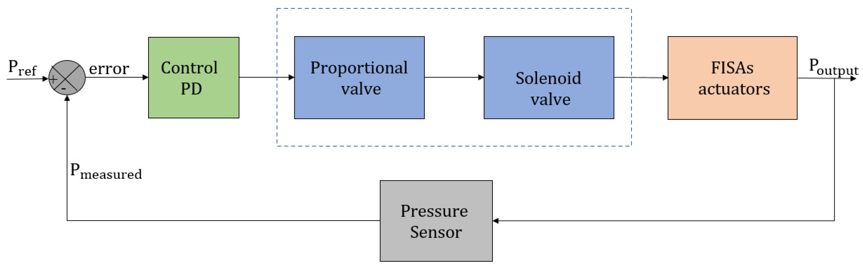
2.4. FISAs Control Design

This section explains the four stages carried out to design the control loop for the inflation-deflation process of the FISAs actuators: (i) the first stage shows the pressure sensor characterization; (ii) the second stage consists of using the switching time characteristics of the implemented valves to determine the PWM modulation frequency and the sampling time of the control loop; (iii) this stage explains how to obtain the transfer function of the system by means of the transient response obtained experimentally; (iv) finally, this stage explains the Proportional Derivative (PD) controller design approach and its implementation in an embedded system to control the FISAs actuator.

2.4.1. Pressure Sensor Characterization

In order to control the opening and closing of the proportional valve, the pressure sensor (ASDXAVX100PGAA5) was characterized to determine the voltage-pressure ratio for accurate flow regulation. Thus, the air pressure was varied from 0 to 50 psi using the Digital to Analog Converter (DAC) signal coming out from the microcontroller (12-bit resolution) goes from 0 V to 3.3 V, but the proportional valve requires 0 V to 5 V, then, a non-inverting operational amplifier circuit (with g a i n = 1.5 ) was implemented for signal conditioning from 0 to 5 V. The proportional valve was opened with a minimum pressure of 3 psi at 1890 of ADC and it remains fully open from 2600 of ADC at maximum pressure. The pressure of the sensor against the ADC values is plotted in Figure 3.

2.4.2. Determining PWM Frequency and Sampling Time

In order to determine the PWM frequency and the sampling time to be implemented in the control loop, it was first necessary to obtain the switching time characteristics of the valves (proportional/solenoid), as is suggested in [38]. Furthermore, the modulation of the PWM frequency ( M f p w m ) can be calculated by using (1):
M f p w m = 1 T o p + T c l
where T o p represents the opening switching time when the solenoid valve is ON after sending the activation signal, and T c l represents the closing switching time when the valve is OFF after sending the deactivation signal. Then, according to the manufacturer specifications, the solenoid valve has T o p = 2.3 ms and T c l = 2.8 ms, and replacing these values in (1) it is obtained a ( M f p w m = 196 Hz), but in practice, this is a high-frequency value which can produce early wear of the valve. Thus, the PWM modulation time was set at 125 Hz to avoid PWM chattering and to increment the lifetime of the valve [38]. With respect to the proportional valve the manufacturer specifications mention that the response time is less than 30 ms, then, to control the opening of this valve by means of the microcontroller DAC output signal and avoid early wear as well, the frequency was set to 40 Hz.
On the other hand, to calculate the sampling time ( T s t ) of the control loop, this one should be greater than the sum of the opening and closing switching time of the solenoid valve, T s t > m a x ( T o p + T c l ) [38]. Then, according to the switching values of the solenoid valve the sampling time was also set to 125 Hz.

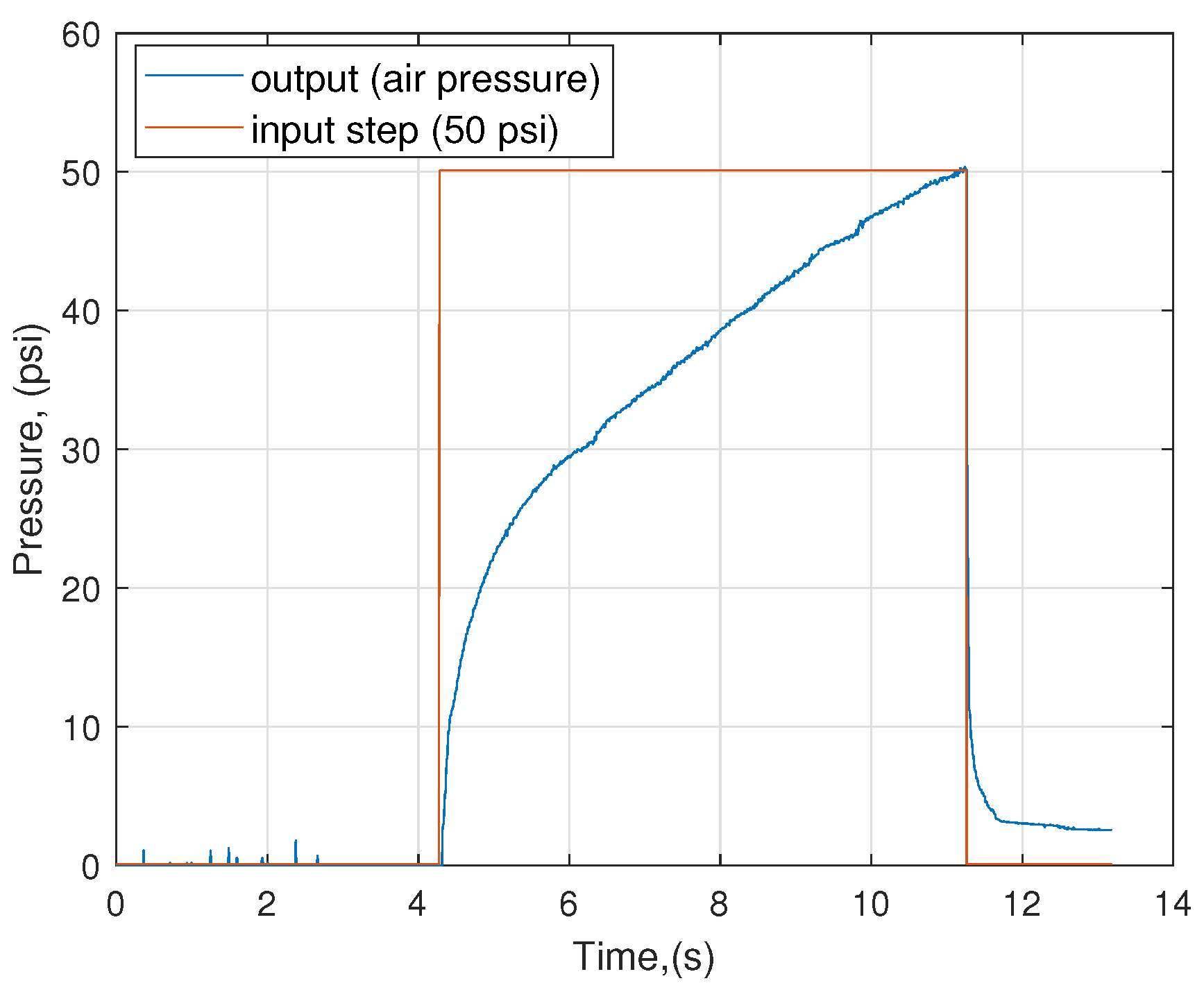
2.4.3. Transient Response and Transfer Function of the System

In order to experimentally obtain the transfer function of the FISAs system, it was necessary to obtain its transient response of it by introducing a step input. In this case, the system was fully integrated with all components as shown in Figure 2, but without controlling the deflation of the system like in open loop mode. The step input was activated during 7 s (to prevent the destruction of the chambers in the FISAs actuator) providing 50 psi to the actuator (i.e., the proportional valve was completely open), then the pressure sensor was only used to monitor the air pressure in the FISAs actuators (see Figure 4).
Once the transient response is obtained, we proceed to obtain a mathematical representation of the system by means of a first-order transfer function. To do so, the System Identification Toolbox of Matlab® was implemented. The result provided by the toolbox was a transfer function with a gain system k = 0.487 and a time constant τ = 0.02872 with a fit equal to 92, as is shown in Equation (2). It is worth mentioning that once the transfer function values were obtained, it is possible to proceed with closed-loop control simulations for tuning the PID controller parameters or other proposed control strategies.
G ( s ) = 0.487 0.2872 s + 1

2.4.4. PD Controller Design Approach

To control the angle of motion of the FISAs actuators by means of the inflation-deflation process which is proportional to air pressure regulation, it is necessary to implement a closed-loop control strategy. Initially, a Proportional-Integral-Derivative (PID) controller was proposed. However, when the inflation process reaches the desired pressure set by the user, the solenoid valve continuously purges (every 200 ms) to maintain the desired pressure and reduce steady-state error, which means more wear and less working time due to fast valve switching. Therefore, to solve these issues, a Proportional-Derivative strategy was proposed instead, to reduce the continuous purge of the valve while keeping close the desired pressure to the steady-state error, as noted in [39].
The PD controller parameters were tuned in simulation, implementing the PID Controller block and the transfer function of the system in the closed-loop configuration using Simulink of Matlab®. The obtained values for the Proportional and Derivative parameters are 1350 and 50, respectively. It is worth mentioning that the values of these parameters were selected to condition the control signal value to the DAC output signal of the microcontroller which has a 12-bit resolution.
In order to test the PD controller and its parameters, it has been designed a closed-loop control in Simulink (see Figure 2 and Figure 5), then, using the RCP options provided by Simulink as explained in [37], the model has been embedded as C program in the microcontroller (Cortex-M7) that contains the NUCLEO-STM32F767ZI™ board. Moreover, the proposed closed-loop control strategy works as follows: the desired air pressure is set by the user as a reference value P r e f , then the proportional valve receives the control signal from the PD controller, then the internal pressure at the output of the soft actuator P o u t p u t , is self-regulated depending on the desired and sensing value P m e a s u r e d . The error, e is calculated from the difference between P r e f and P m e a s u r e d . If the error is ≥0, then FISAs will inflate, otherwise, they will deflate, i.e., the solenoid valve is activated to purge excess air into the atmosphere.

3. Experimental Results

Once the design, fabrication, and control of FISAs actuators were achieved. Preliminary experiments on FISAs performance were carried out to guarantee their operation above the MOSAR system. Therefore, three experimental tests related to their inflation-deflation time, Range of Motion, and output force were evaluated to achieve elbow flexion extension in a dummy limb of 370 g. Figure 6 illustrates the experimental setup along with the assembly of FISAs actuators on the MOSAR system.

3.1. Inflation-Deflation Time

The time elapsed between the pressurization and depressurization was evaluated when elbow mobilization occurs on a dummy limb with the dimensions of an 8-year-old child and a pressure from 0 to 50 psi. Therefore, two different assessments were performed to measure the inflation T i f and deflation T d f time when the actuators were partially inflated or totally deflated.
Figure 7a illustrates the inflation process to an input step signal. The actuators started to inflate after 7.5 s when pressure was above 3 psi and another 5 s were needed for full inflation at maximum pressure. Whereas Figure 7b includes both actions, FISAs are fully inflated in 12 s and started to depressurize when they reach 50 psi, and took them around 5 s to deflate completely. Obviously, both processes occur faster when the actuators are partially inflated or deflated, since less depressurization is required. It can be observed in both figures that there is an error of less than 1%, since the system is able to reach 49.29 of 50 psi in real-time.
Furthermore, the time for supplying and exhausting pressure of the FISAs for the MOSAR system operation represents a feasible and safe tool for being used in rehabilitation protocols compared to other designs since they will not harm users when elbow flexion-extension is executed. However, vacuum ejectors can be used as another option to reduce the inflation time, if it is necessary [36].

3.2. Range of Motion
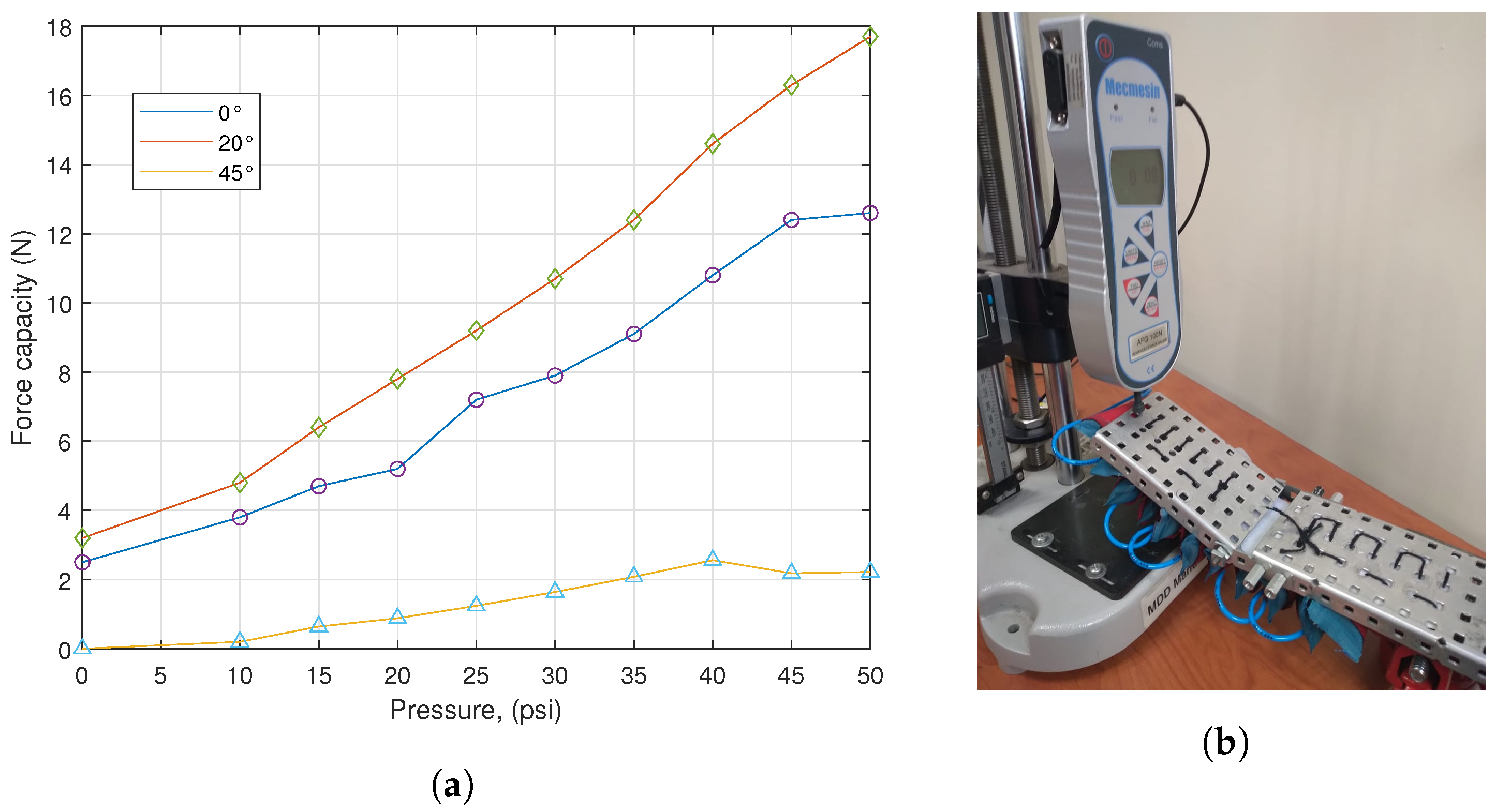
The Range of Motion was measured to evaluate the capacity of the MOSAR system to achieve natural elbow flexion-extension, considering that a human upper limb represents the 5% of the total weight of the human body [40] and activities of daily living normally require 30 ° for elbow flexion [33].
Therefore, three experimental tests were carried out to measure the bending angle using a manual goniometer. FISAs actuators were mounted on an aluminum plate that was set at 180 ° as a reference, and then the actuators started to be pressurized above it to lift three steel cylinder weights of 0.5 kg, 1 kg, and 2 kg when the pressure was varied from 0 to 50 psi.
The results show that FISAs have the capacity to lift 1.5 kg using only 12 chambers. They were able to bend internally from 20 ° –30 ° at maximum pressure when they were flexed, and also can bend up to 70 ° with 0.5 kg, as plotted in Figure 8. The ROM of the FISAs actuators agrees with the natural ROM of a healthy patient which means that they can be applied for elbow motion and for other joints that include bending tasks.

3.3. Output Force

To continue with the assessment of FISAs actuators, their lift force capacity was determined using an electronic Force Gauge Mecmesin™ with a capacity of 100 N. This experiment consisted to apply a normal force when they were placed horizontally on an aluminum plate, at different angles of 0 ° , 20 ° and 45 ° , while the pressure was varied from 5 psi to 50 psi.
During the experiment, FISAs actuators were able to lift a maximum force of 18 N when the base plane was set at an angle of 20 ° , and 50 psi were applied. Whereas a minimum force of 2 N was computed when the angle was set at 45 ° , the larger the angle, the smaller the force produced, since the sensor points down; finally, 12.5 N was obtained when the base plane was normal to the gauge. All these measurements can be observed in Figure 9, they have demonstrated that the FISAs actuators have the capacity to lift an elbow of a child which only needs 16 N as is noted in [40].

4. Discussion

Several applications related to Soft Robotics have taken advantage of the air since it is as a powerful plenty natural resource that does not pollute. Thus, the air has been demonstrated to be a feasible fluid for Soft Pneumatic Actuators with multiple degrees of freedom. Therefore, several technological advances related to inflatable structures have been done during the last decade for driving Soft Robots due to their flexibility, lightness, safety, costs, and output forces. However, handling and storing compressible fluids in inflatable actuators have been a challenge. There are still several issues to face in optimizing their design, fabrication, and control, especially those which are focused on medical applications.
Therefore, this research has presented a detailed description of the Fabric Inflatable Soft Actuators to drive soft wearable devices for rehabilitation or assistance tasks, using a modular design for their assembly with a simple fabrication process and real-time control for their inflation-deflation process. The concept of FISAs has been inspired by the “domino effect” to produce the same chain reaction when the actuators are pressurized. Thus, the geometrical parameters of the FISAs chambers must be defined to reach maximum pressurization depending on the target trajectory and required pressure to achieve a specific motion on a surface. Otherwise, FISA chambers would behave like a bunch of grapes, they will overlap with each other, and no force is produced.
The fabrication of inflatable actuators with the ability to contain pressurized fluid into elastic structures with multiple degrees of freedom and without air leaks has been a challenge. Current methods are still looking for materials with minimum stiffness and high payload capacity under high compression stress to reach higher pressures. Additionally, fabrication methods should look for simple, fast, and cost-effective procedures to test the actuators. Unlike other proposals, FISAs fabrication was presented as a handcrafted process since it involves manipulation skills under the do-it-yourself approach to make it accessible for all people interested in Soft Robotics applications. The main advantage of the FISA fabrication process is that custom designs can be obtained, or they can be scaled to different anthropometric ranges. Likewise, the components and equipment are commercially available, so this type of fabrication allows the chambers to be tested or replaced immediately and their costs are low compared to the Silicone process which requires sophisticated equipment or is more time-consuming.
Regarding SPAs control, mostly PID strategies have been implemented because they provide stability to the systems with a minimum error during pressure sensing [21]. However, it has been demonstrated during the experimental work of this research, that this control strategy is not a suitable option when solenoid valves are used. Since PID control strategy increases the wear of solenoid valves, because they are venting all the time to keep the desired value, so their lifetime is affected. Hence, a PD control strategy was a better choice to compensate for the error, avoid chattering and extend the life use of the solenoid valve. Moreover, the solenoid and proportional valves assembly turned out a balance among speed, accuracy, regulation, and costs during the inflation-deflation process of FISAs actuators, since Proportional Valves have greater delay time than Solenoid Valves in real time.
Furthermore, the use of the NUCLEO-STM32F767ZI™ board, as an embedded system that offers RCP options using Simulink of Matlab®, was another contribution of this paper, since a faster response was obtained in real-time compared to ARDUINO™ control schemes for all the elecro-pneumatic system. Additionally, channels such as ADC or DAC are already included which means savings on components, programming, and costs. Therefore, it is recommended to make an analysis to evaluate all these factors.
It is worth mentioning that FISAs performance was evaluated in a Soft Exo-sleeved called MOSAR system to achieve elbow mobilization. This exosuit weighs only 100 g and has an easy donn-off to provide intuitive use. Thus, experimental tests were successfully carried out above a dummy limb to guarantee FISA operation during bending motions. Whereby, FISAs actuators could be also applied to other joints that involve flexion-extension motion such as the knee, wrist, or fingers for example, or even in other assistance tasks under the approach of Soft Robotics. However, for rehabilitation protocols, we recommend testing FISAs first on healthy people and later on users with impaired limbs, and always under the supervision of therapists or doctors to assess patient progress.
The main advantages of FISAs actuators are: (1) their compact design that avoids cumbersome structures compared to other inflatable actuators with high dimensions (see Table 1). (2) a self-fabrication process for their modular assembly that allows the chambers to be easily changed or replaced. Thus, FISAs can be adapted to different limbs, regardless of age, sex, or length, only the number of chambers must be defined. (3) the use of the NUCLEO-STM32F767ZI™ board (using a microcontroller Cortex-M7) with RPC capabilities provides accurate control pressure and sensing in real-time during the inflation-deflation process. Thus, FISAs represent a feasible option for elbow mobilization and for other joints that include bending motions, such as the knee, wrist, hand, or fingers. Exo-Sleeve called MOSAR system.
Most efforts related to inflatable actuators seek to become an aid tool for therapists or solve the demands of clinics that do not have available facilities or therapists for patients with restricted mobility [33]. Hence, inflatable actuators for driving Soft Wearable Devices should focus on three main tasks: (1) to perform or guide patients to accomplish a specific motion on a target limb, (2) to increase their Range of Motion, and (3) to make users feel comfortable and engaged during the therapy. This will be possible if we work closely with therapists to monitor the process.
Moreover, several breakthroughs related to inflatable actuators have been done. However, pneumatic systems such as FISAs are still requiring compact portable units, since they are connected to a stationary air inlet supply or compressor units that require electricity for air pressurization. Thus, compact storage tanks similar to Oxygen ones are suggested so that users can move freely. Similarly, materials resistant to air leaks with low cost and with high payload capacity must be available for the developers during their manipulation to be off-the-shelf products, since the inflatable can generate high forces with low air pressurization.
Inflatable actuators have opened a window of opportunities for developing medical technology applied to rehabilitation or assistance tasks, using a clean power source. We should foster and bet on new developments, as available and low-cost products for being a feasible alternative for users, therapists, or hospitals, in the short run. Additionally, other options for the electro-pneumatic assembly should be sought, since they represent the highest cost of this type of system. In particular, Proportional Valves have a large range of bandwidths but are expensive. Whereas Solenoid Valves are cheap, their high switching frequency reduces their lifetime. Nevertheless, this assembly has shown a fast and accurate response when the supply and exhaust pressure of FISAs actuators is controlled during bending-extending. Thus, the proposed control can be used in other applications of Soft Robots with pneumatic actuation, for one or more DOF, but a trade-off between costs-components-operation is needed.

5. Conclusions

In this study, we addressed a specific type of Soft Pneumatic Actuators for driving Soft Wearable Robots applied to rehabilitation or assistance tasks. Thus, we present a detailed description of the design, fabrication, and control of Fabric Inflatable Soft Actuators called FISAs. These actuators were created for executing bending and extending motions into the MOSAR system, a Soft Exo-Sleeve of 100 g that was developed for elbow mobilization of an 8-year-old child, a case study previously introduced in [33].
Therefore, to overcome the natural growth of the child, a modular configuration has been proposed to adapt FISAs actuators to any anatomy, no matter the length, age, or sex. Regarding their development, a hand-craft process has been applied under the DIY approach for encouraging all people interested in Soft Robotics, using a simple and fast assembly, only by adding or removing chambers from a base layer that imitated the domino effect to achieve maximum pressure when bending occurs, only geometrical parameters must be defined to reach maximum pressurization on a circular cross-section area for the target limb.
Another contribution from this paper is the proposed real-time control scheme using a proportional and solenoid valve assembly for accurate pressure regulation on an embedded board (NUCLEO-STM32F767ZI ™) with RCP. Hence, a PD control strategy was implemented for pressure sensing characterization where the delay time was measured and the transfer function of the system was obtained. The results of this experimental setup have reduced the inflation-deflation time with a fast response for flexion-extension movements. FISAs could inflate in 12 s with an error less than 1% on the steady-state at 50 psi. Hence, FISAs represent a trade-off between components and operation costs due to their rapid fabrication that makes them available and feasible actuators for soft robots.
Furthermore, FISAs performance was evaluated on a Soft Wearable Exo-Sleeve called MOSAR system to achieve elbow motion. The MOSAR was integrated by a set of 12 TPU FISAs chambers which allows a compact structure when they are inflated or deflated. Additionally, it reduces their number, dimensions, and increases pressure output for elbow mobilization compared to other works that were shown in Table 1. From these preliminary experiments, we have demonstrated FISAs functionality above the MOSAR system. FISAs provide a ROM of 130 ° and lift 16 N above a dummy limb similar to child anatomy. These results exceed the required force for elbow mobilization using less pressure. For future work, FISAs actuators and the Soft Exo-sleeve MOSAR system will be tested first on healthy people to validate their functionality, and then on patients with impaired upper limbs, specifically on elbow mobilization.
Therefore, FISAs represent a new approach to medical Soft Robotics actuation, they can be applied to other Soft Wearable Robots that can include passive-active rehabilitation or assistance tasks, for instance, only the geometrical parameters must be defined. FISAs do not seek to replace the work of therapists or healthcare workers but are useful tools and aids for people with upper or lower limb disabilities during their rehabilitation protocols. There should be always contact between patients and therapists to monitor their progress and define their routines. Hence, this type of textile actuator, along with the electro-pneumatic system, provides a trade-off between costs-manufacture-operation due to their rapid fabrication and accurate pressure regulation that makes them available and feasible actuators for soft robots. Nevertheless, the more DOF, the more complexity of the system, but larger forces could be obtained depending on the degree of pressurization.

Author Contributions

Conceptualization, J.-M.D.-V.; methodology and validation, J.-M.D.-V. and J.M.J.-V.; resources L.A.Z.-A.; writing—original draft preparation, J.-M.D.-V.; writing—review and editing, J.-M.D.-V., J.C.Á.-V., A.H.V.-G., L.A.Z.-A. and J.M.J.-V.; visualization, J.C.Á.-V. and L.A.Z.-A.; supervision, J.M.J.-V.; project administration, A.H.V.-G.; funding acquisition, J.C.Á.-V. All authors have read and agreed to the published version of the manuscript.

Funding

This research was funded by COMECYT (Consejo Mexiquense de Ciencia y Tecnología) grant number CAT2021-0005.

Informed Consent Statement

This work does not include any studies with human participants.

Data Availability Statement

Not applicable.

Acknowledgments

Authors want to thank Leonardo Daga for providing the RS32 Simulink communication libraries in real-time.

Conflicts of Interest

The authors declare that they have no conflict of interest.

Abbreviations

The following abbreviations are used in this manuscript:
ADCAnalog Digital Converter
DACDigital Analog Converter
DIYDo It Yourself
DOFDegrees of Freedom
ESDElectrostatic Discharge
FEAsFluid Elastomer actuators
FEMFinite Element Method
FISAsFabric Inflatable Soft Actuators
LDPELow Density Polyethylene
PAMsPneumatic Artificial Muscles
PDProportional-Derivative
PIDProportional-Integral-Derivative
PVProportional Valves
PVCPolymerizing Vinyl Chloride
RCPRapid Control Prototyping
ROMRange of Motion
SPAsSoft Pneumatic Actuators
SVSolenoid Valves
SWDSoft Wearable Soft Devices
TPUThemoplastic Polyurethane

References

  1. Polygerinos, P.; Correll, N.; Morin, S.A.; Mosadegh, B.; Onal, C.D.; Petersen, K.; Cianchetti, M.; Tolley, M.T.; Shepherd, R.F. Soft Robotics: Review of Fluid Driven Intrinsically Soft Devices; Manufacturing, Sensing, Control, and Applications in Human-Robot Interaction. Adv. Eng. Mater. 2017, 19, 1700016. [Google Scholar] [CrossRef]
  2. Nguyen, P.H.; Sparks, C.; Nuthi, S.G.; Vale, N.M.; Polygerinos, P. Soft Poly-Limbs: Toward a New Paradigm of Mobile Manipulation for Daily Living Tasks. Soft Robot. 2019, 6, 38–53. [Google Scholar] [CrossRef] [PubMed]
  3. Dávila-Vilchis, J.M.; Ávila Vilchis, J.C.; Vilchis-González, A.H.; LAZ-Avilés. Design Criteria of Soft Exogloves for Hand Rehabilitation-Assistance Tasks. Appl. Bionics Biomech. 2020, 2020, 2724783. [Google Scholar] [CrossRef] [PubMed]
  4. Nguyen, P.H.; Mohd, I.B.I.; Sparks, C.; Arellano, F.L.; Zhang, W.; Polygerinos, P. Fabric Soft Poly-Limbs for Physical Assistance of Daily Living Tasks. In Proceedings of the 2019 International Conference on Robotics and Automation (ICRA), Montreal, QC, Canada, 20–24 May 2019. [Google Scholar] [CrossRef]
  5. Kaspar, A. Antagonistic actuation and stiffness control in soft inflatable robots. Nat. Rev. Mater. 2018, 3, 76–77. [Google Scholar] [CrossRef]
  6. Miriyev, A.; Stack, K.; Lipson, H. Soft material for soft actuators. Nat. Commun. 2017, 8, 596. [Google Scholar] [CrossRef] [PubMed]
  7. Yap, H.K.; Lim, J.H.; Goh, J.C.H.; Yeow, C.H. Design of a Soft Robotic Glove for Hand Rehabilitation of Stroke Patients with Clenched Fist Deformity Using Inflatable Plastic Actuators. J. Med. Devices 2016, 10, 044504. [Google Scholar] [CrossRef]
  8. Nguyen, P.H.; Sridar, S.; Amatya, S.; Thalman, C.M.; Polygerinos, P. Fabric-Based Soft Grippers Capable of Selective Distributed Bending for Assistance of Daily Living Tasks. In Proceedings of the 2019 2nd IEEE International Conference on Soft Robotics (RoboSoft), Seoul, Korea, 14–18 April 2019; pp. 404–409. [Google Scholar] [CrossRef]
  9. Gorissen, B.; Reynaerts, D.; Konishi, S.; Yoshida, K.; Kim, J.W.; Volder, M.D. Elastic Inflatable Actuators for Soft Robotic Applications. Adv. Eng. Mater. 2017, 29, 1604977. [Google Scholar] [CrossRef]
  10. Mosadegh, B.; Polygerinos, P.; Keplinger, C.; Wennstedt, S.; Shepherd, R.F.; Gupta, U.; Shim, J.; Bertoldi, K.; Walsh, C.J.; Whitesides, G.M. Pneumatic Networks for Soft Robotics that Actuate Rapidly. Adv. Eng. Mater. 2014, 24, 2163–2170. [Google Scholar] [CrossRef] [Green Version]
  11. Polygerinos, P.; Lyne, S.; Wang, Z.; Nicolini, L.F.; Mosadegh, B.; Whitesides, G.M.; Walsh, C.J. Towards a soft pneumatic glove for hand rehabilitation. In Proceedings of the 2013 IEEE/RSJ International Conference on Intelligent Robots and Systems, Tokyo, Japan, 3–7 November 2013; pp. 1512–1517. [Google Scholar] [CrossRef]
  12. Hofer, M.; D’Andrea, R. Design, Modeling and Control of a Soft Robotic Arm. In Proceedings of the International Conference on Intelligent Robots and Systems, Madrid, Spain, 1–5 October 2018; pp. 1456–1463. [Google Scholar] [CrossRef]
  13. Paez-Granados, D.; Yamamoto, T.; Kadone, H.; Suzuki, K. Passive Flow Control for Series Inflatable Actuators: Application on a Wearable Soft-Robot for Posture Assistance. IEEE Robot. Autom. Lett. 2021, 6, 4891–4898. [Google Scholar] [CrossRef]
  14. Nishioka, Y.; Uesu, M.; Tsuboi, H.; Kawamura, S.; Masuda, W.; Yasuda, T.; Yamano, M. Development of a pneumatic soft actuator with pleated inflatable structures. Adv. Robot. 2017, 31, 753–762. [Google Scholar] [CrossRef]
  15. Oguntosin, V.; Harwin, W.S.; Kawamura, S.; Nasuto, S.J.; Hayashi, Y. Development of a wearable assistive soft robotic device for elbow rehabilitation. In Proceedings of the 2015 IEEE International Conference on Rehabilitation Robotics (ICORR), Singapore, 11–14 August 2015. [Google Scholar] [CrossRef]
  16. Thalman, C.M.; Lam, Q.P.; Nguyen, P.H.; Sridar, S.; Polygerinos, P. A Novel Soft Elbow Exosuit to Supplement Bicep Lifting Capacity. In Proceedings of the 2018 IEEE/RSJ International Conference on Intelligent Robots and Systems (IROS), Madrid, Spain, 1–5 October 2018. [Google Scholar] [CrossRef]
  17. O’Neill, C.T.; Phipps, N.S.; Cappello, L.; Paganoni, S.; Walsh, C.J. A soft wearable robot for the shoulder: Design, characterization, and preliminary testing. In Proceedings of the 2017 International Conference on Rehabilitation Robotics (ICORR), London, UK, 17–20 July 2017; pp. 1672–1678. [Google Scholar] [CrossRef]
  18. Wang, Y.; Lo, B. A Soft Inflatable Elbow-Assistive Robot for Children with Cerebral Palsy. In Proceedings of the 2021 IEEE 17th International Conference on Wearable and Implantable Body Sensor Networks (BSN), Virtual, 27–30 July 2021; pp. 1–4. [Google Scholar] [CrossRef]
  19. Park, S.H.; Yi, J.; Kim, D.; Lee, Y.; Koo, H.S.; Park, Y.L. A Lightweight, Soft Wearable Sleeve for Rehabilitation of Forearm Pronation and Supination. In Proceedings of the 2019 2nd IEEE International Conference on Soft Robotics (RoboSoft), Seoul, Korea, 14–18 April 2019. [Google Scholar] [CrossRef]
  20. Sridar, S.; Qiao, Z.; Muthukrishnan, N.; Zhang, W.; Polygerinos, P. A soft-inflatable exosuit for knee rehabilitation: Assisting swing phase during walking. Front. Robot. AI 2018, 5, 44. [Google Scholar] [CrossRef] [Green Version]
  21. Thuruthel George, T.; Ansari, Y.; Falotico, E.; Laschi, C. Control Strategies for Soft Robotic Manipulators: A Survey. Soft Robot. 2018, 5, 149–163. [Google Scholar] [CrossRef] [PubMed]
  22. Huang, H.; Wu, L.; Lin, J.; Fang, B.; Sun, F. A novel mode controllable hybrid valve pressure control method for soft robotic gripper. Int. J. Adv. Robot. Syst. 2018, 15, 1–12. [Google Scholar] [CrossRef]
  23. Li, X.; Guo, C.; Liu, T.; Hong, L. Design, modeling and characterization of a joint for inflatable robotic arms. Mechatronics 2020, 65, 102311. [Google Scholar] [CrossRef]
  24. Pipan, M.; Herakovič, N. Volume flow characterization of PWM-controlled fast-switching pneumatic valves. Strojniški Vestnik J. Mech. Eng. 2016, 62, 543–550. [Google Scholar] [CrossRef]
  25. Elgeneidy, K.; Lohse, N.; Jackson, M. Bending angle prediction and control of soft pneumatic actuators with embedded flex sensors—A data-driven approach. Mechatronics 2018, 50, 234–247. [Google Scholar] [CrossRef]
  26. Qiao, Z.; Nguyen, P.H.; Polygerinos, P.; Zhang, W. Dynamic Modeling and Motion Control of a Soft Robotic Arm Segment. In Proceedings of the 2019 American Control Conference (ACC), Philadelphia, PA, USA, 10–12 July 2019; pp. 5438–5443. [Google Scholar] [CrossRef]
  27. Katzschmann, R.K.; Thieffry, M.; Goury, O.; Kruszewski, A.; Guerra, T.M.; Duriez, C.; Rus, D. Dynamically Closed-Loop Controlled Soft Robotic Arm using a Reduced Order Finite Element Model with State Observer. In Proceedings of the 2019 2nd IEEE International Conference on Soft Robotics (RoboSoft), Seoul, Korea, 14–18 April 2019; pp. 717–724. [Google Scholar] [CrossRef]
  28. Largilliere, F.; Verona, V.; Coevoet, E.; Sanz-Lopez, M.; Dequidt, J.; Duriez, C. Real-time Control of Soft-Robots using Asynchronous Finite Element Modeling. In Proceedings of the 2015 IEEE International Conference on Robotics and Automation (ICRA), Seattle, WA, USA, 25–30 May 2015; pp. 1–6. [Google Scholar] [CrossRef]
  29. Moseley, P.; Florez, J.M.; Sonar, H.A.; Gunjan Agarwal, W.C.; Paik, J. Modeling, design, and development of soft pneumatic actuators with finite element method. Adv. Eng. Mater. 2016, 18, 978–988. [Google Scholar] [CrossRef]
  30. Nguyen, P.H.; Lopez-Arellano, F.; Zhang, W.; Polygerinos, P. Design, Characterization, and Mechanical Programming of Fabric-Reinforced Textile Actuators for a Soft Robotic Hand. In Proceedings of the International Conference on Intelligent Robots and Systems, Macau, China, 4–8 November 2019. [Google Scholar] [CrossRef]
  31. Nguyen, P.H. and Zhang, W. Design and Computational Modeling of Fabric Soft Pneumatic Actuators for Wearable Assistive Devices. Sci. Rep. 2020, 10, 9638. [Google Scholar] [CrossRef]
  32. Gil-Agudo, A.; del Ama-Espinosa, A.; De la Pena-González, A.; Bernal-Sahún, A.; Rocón, E. Applications of Upper Limb Biomechanical Models in Spinal Cord Injury Patients. Biomech. Appl. 2011, 1, 129–164. [Google Scholar] [CrossRef]
  33. Dávila-Vilchis, J.M.; LAZ-Avilés; Ávila Vilchis, J.C.; Vilchis-González, A.H. Design Methodology for Soft Wearable Devices—The MOSAR Case. Appl. Sci. 2019, 9, 4727. [Google Scholar] [CrossRef]
  34. Ozlem, U.; Yeginoglu Gulay, C.E.; Nur, K.S. Estimation of Stature from Upper Extremity Anthropometric Measurements. J. Clin. Diagn. Res. 2019, 13, 9–15. [Google Scholar] [CrossRef]
  35. Nassour, J.; Hamker, F.H.; Cheng, G. High-Performance Perpendicularly-Enfolded-Textile Actuators for Soft Wearable Robots: Design and Realization. IEEE Trans. Med. Robot. Bionics 2020, 2, 309–319. [Google Scholar] [CrossRef]
  36. Park, J.; Choi, J.; Kim, S.J.; Seo, K.H.; Kim, J. Design of an Inflatable Wrinkle Actuator With Fast Inflation/Deflation Responses for Wearable Suits. IEEE Robot. Autom. Lett. 2020, 5, 3799–3805. [Google Scholar] [CrossRef]
  37. Jacinto-Villegas, J.M.; Portillo-Rodríguez, O.; Martinez-Mendez, R.; Daza-Merino, C.; Vilchis-González, A.H.; Avila-Vilchis, J.C. Sistema para control de posición basado en Rapid Control Prototyping (RCP) usando Simulink y SWB32. Komput. Sapiens 2019, 3, 11–15. [Google Scholar]
  38. Le, M.Q.; Pham, M.T.; Moreau, R.; Redarce, T. Comparison of a PWM and a hybrid force control for a pneumatic actuator using on/off solenoid valves. In Proceedings of the 2010 IEEE/ASME International Conference on Advanced Intelligent Mechatronics, Montreal, QC, Canada, 6–9 July 2010; pp. 1146–1151. [Google Scholar] [CrossRef]
  39. Astrom, K.J.; Hägglund, T. Control PID Avanzado; Pearson: Madrid, Spain, 2019. [Google Scholar]
  40. Osterkamp, L.K. Current Perspective on Assessment of Human Body Proportions of Relevance to Amputees. J. Am. Diet. Assoc. 1995, 95, 215–218. [Google Scholar] [CrossRef]
Figure 1. FISAs geometrical parameters on a front view: (a) shows the base length bl, wall thickness wt, gap g, height of air channel h and width of chambers w. (b) shows the angle of attack between the air inlet and base length, α , and the number of chambers n in a semicircular path. (c) FISAs assembly a: air chambers, b: T connectors, c: inelastic fabric layer, d: fabric chambers containers and e: air tubing.
Machines 10 00871 g001
Figure 2. Block diagram of the FISAs system to control the inflation-deflation process.
Machines 10 00871 g002
Figure 3. Pressure sensing control scheme of FISAs actuators.
Machines 10 00871 g003
Figure 4. Transient response of the FISAs system that was obtained experimentally.
Machines 10 00871 g004
Figure 5. FISAs pressure sensing in a closed-loop control scheme.
Machines 10 00871 g005
Figure 6. Experimental setup of FISAs above the MOSAR system with all the components.
Machines 10 00871 g006
Figure 7. FISAs inflation-deflation time. (a) FISAs inflation process. (b) FISAs deflation process.
Machines 10 00871 g007
Figure 8. Range of Motion test of FISAs when lifting 0.5 kg, 1.5 kg, and 2 kg. (a) Pressure vs. Degrees test. (b) FISAs and weights setup.
Machines 10 00871 g008
Figure 9. FISAs payload capacity test. (a) Pressure vs. Force test. (b) Force Gauge and FISAs setup.
Machines 10 00871 g009
Table 1. FISAs features and comparison with other inflatable structures for rehabilitation tasks.
Inflatable ActuatorsDimensionsPressureMaterialWeightInterface
Soft modules [15]100 mm × 60 mm0–50 kPaEcoFlex0030®350 gArduino
Soft Actuator [16]50 mm × 50 mm300 kPaTPU-nylonArduino
Inflatable bladders [12]110 mm × 90 mm450 kPaRivertex 842®(DS1104R&D)
Serial Inflatable actuators [13]60 mm × 350 mm20–50 kPaPVC
Inflatable structures [14]50 mm × 300 mm20 kPaLDPE13.2 gArduino
FISAs35 mm × 70 mm300 kPa200D TPU-nylon100 gNUCLEO-STM32F767ZI™
Publisher’s Note: MDPI stays neutral with regard to jurisdictional claims in published maps and institutional affiliations.

