
A Two-DOF Active-Passive Hybrid Vibration Isolator Based on Multi-Line Spectrum Adaptive Control
Abstract
:1. Introduction
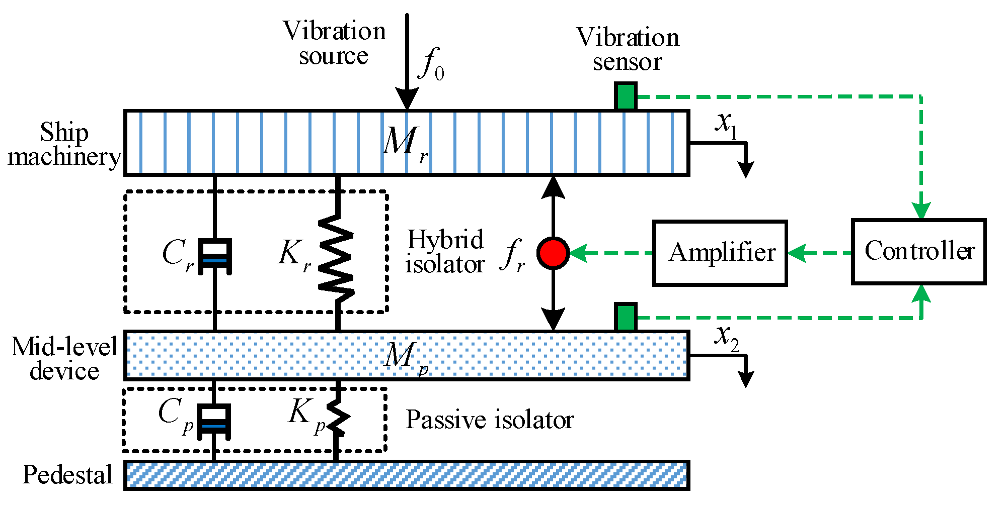
2. Theoretical Analysis of the Two-DOF Vibration Isolator
- (1)
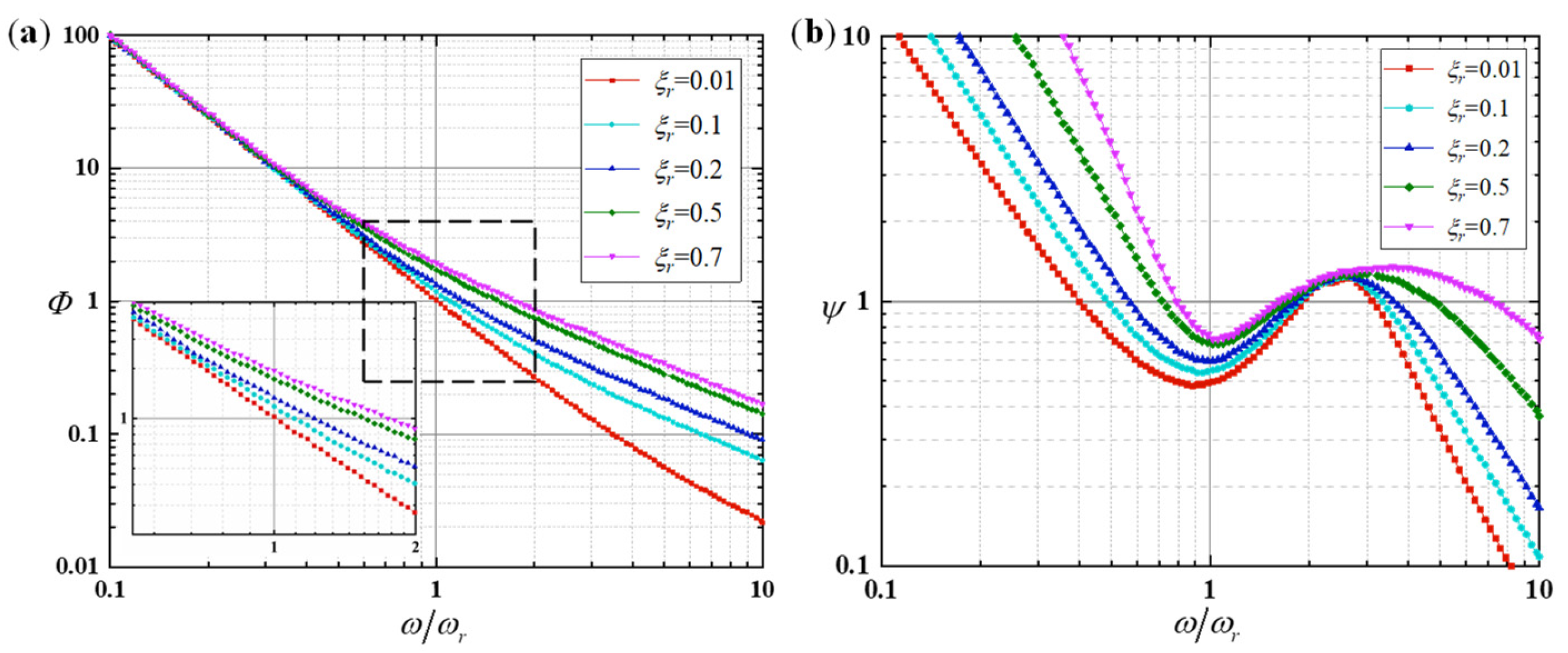
- When the frequency ratio is smaller than 1, the required active control force is greater than the excitation force; when , the required force is close to the excitation force. When , the required force is smaller than the excitation force (), and the larger is , the smaller force will be required. In addition, “” is smaller when is smaller in the same frequency band.
- (2)
- When and is small, not only the vibration displacement magnitude transmitted to the pedestal will be attenuated, but also the vibration displacement magnitude of machinery will not be increased after active control. When , the machinery vibration displacement magnitude is decreased significantly. However, when , the vibration displacement magnitude is increased slightly.Considering the influence of comprehensive performance parameters on the vibration isolation performance, the two-DOF hybrid vibration isolation system has the following characteristics: (1) In order to obtain an ideal active control force, the damping ratio should be as small as possible; (2) after active control, the vibration of the controlled object will increase only in a small frequency band.
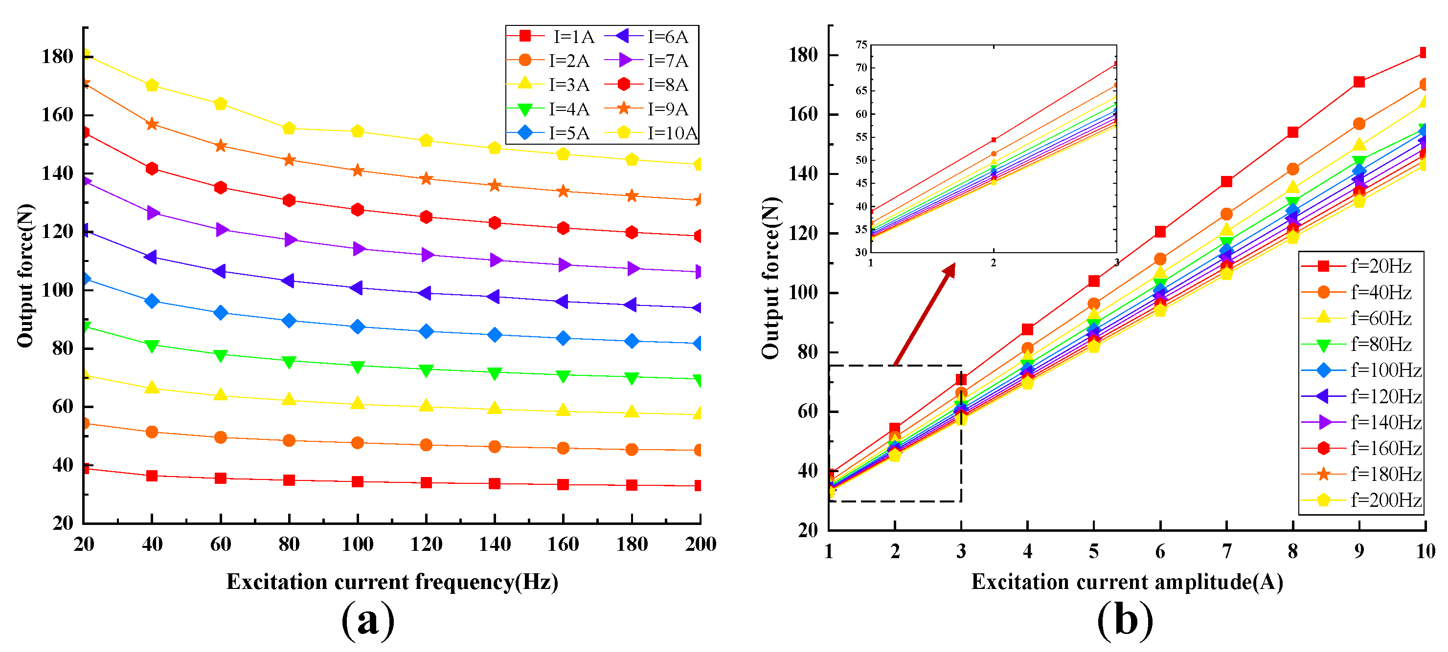
3. Design of the Active and Passive Hybrid Vibration Isolator
4. Multi-Line Spectrum Adaptive Control Algorithm
4.1. Improved Wavelet Packet Decomposition Algorithm
4.2. Hartley Domain Block Algorithm
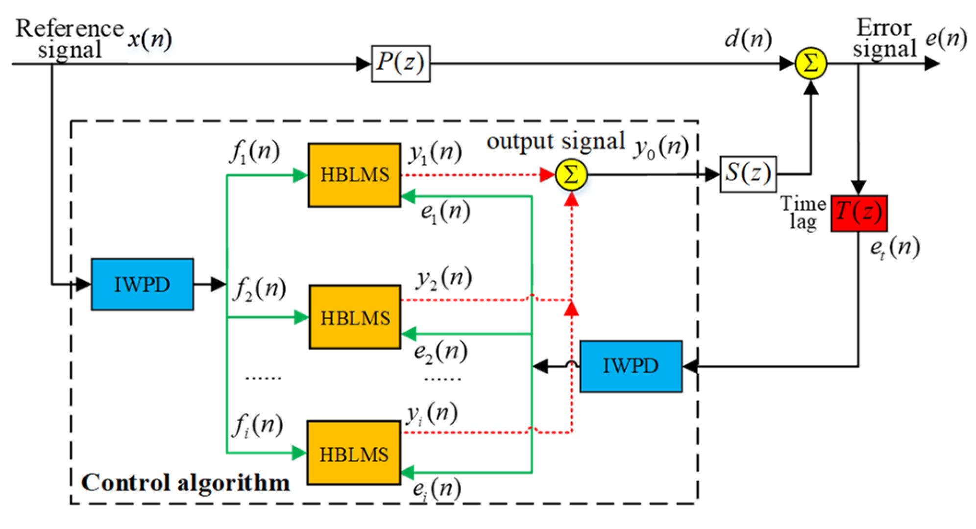
4.3. Multi-Line Spectrum Adaptive Control Algorithm
- (1)
- The process of signal acquisition and transmission between hardware.
- (2)
- The operation process of preprocessing an iterative update of the acquired signal.
- (3)
- The transmission process of the output signal to the error signal sensor.
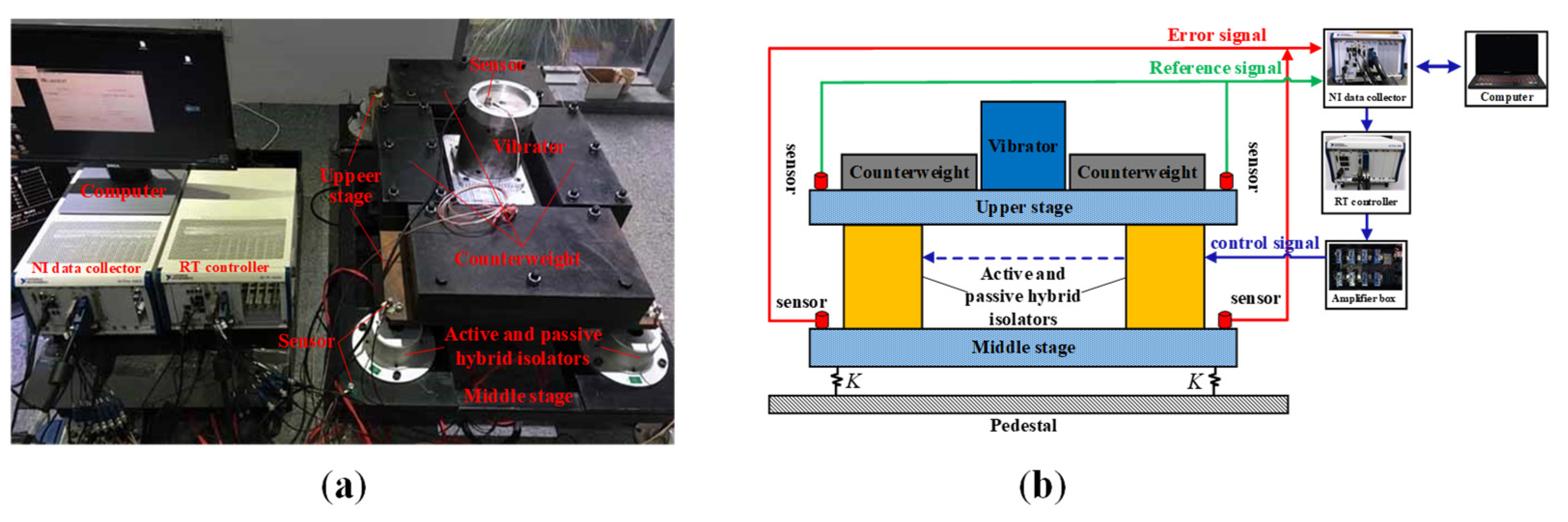
5. Experiment
5.1. Passive Vibration Isolation Experiment
5.2. Active Control Experiment of Constant Frequency Excitation
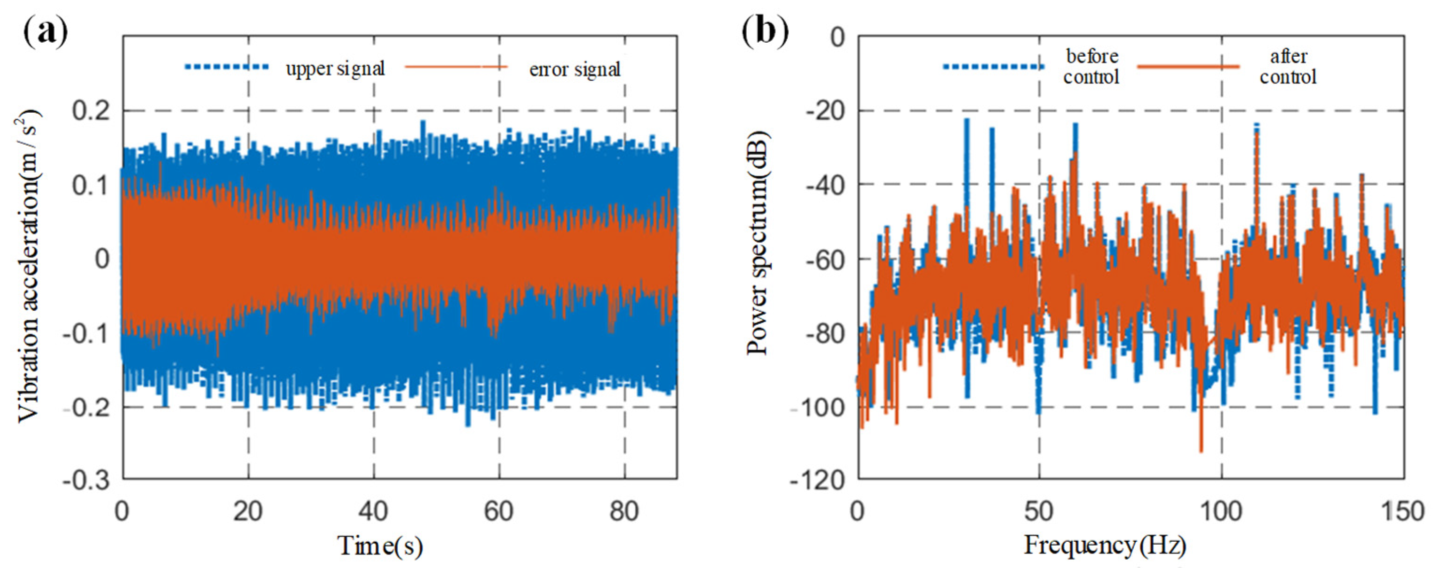
5.3. Active Control Experiment of Multi-Frequency Line Spectrum Excitation
6. Conclusions
Author Contributions
Funding
Institutional Review Board Statement
Informed Consent Statement
Data Availability Statement
Conflicts of Interest
References
- Ross, D. Mechanics of Underwater Noise; Pergamon Press: New York, NY, USA, 1976. [Google Scholar] [CrossRef]
- Shi, Y.; Zhu, S.; He, L. Noise Control of Marine Power Machinery; National Defense Industry Press: Beijing, China, 1998. [Google Scholar]
- Chen, R.; Li, X.; Yang, Z.; Xu, J.; Yang, H. A variable positive-negative stiffness joint with low frequency vibration isolation performance. Measurement 2021, 185, 110046. [Google Scholar] [CrossRef]
- He, K.; Li, Q.; Liu, L.; Yang, H. Active vibration isolation of ultra-stable optical reference cavity of space optical clock. Aerosp. Sci. Technol. 2021, 112, 106633. [Google Scholar] [CrossRef]
- Rasid, S.M.R.; Mizuno, T.; Ishino, Y.; Takasaki, M.; Hara, M.; Yamaguchi, D. Design and control of active vibration isolation system with an active dynamic vibration absorber operating as accelerometer. J. Sound Vibr. 2019, 438, 175–190. [Google Scholar] [CrossRef]
- Ding, J.; Wang, Y.; Wang, M.; Sun, Y.; Peng, Y.; Luo, J.; Pu, H. An active geophone with an adjustable electromagnetic negative stiffness for low-frequency vibration measurement. Mech. Syst. Signal Proc. 2022, 178, 109207. [Google Scholar] [CrossRef]
- Phu, D.; Choi, S. Vibration control of a ship engine system using high-load magnetorheological mounts associated with a new indirect fuzzy sliding mode controller. Smart Mater. Struct. 2014, 24, 25009. [Google Scholar] [CrossRef]
- Nguyen, Q.; Phu, D.; Park, J.; Choi, S.; Kang, O. Development of high damping magneto-rheological mount for ship engines. Appl. Mech. Mater. 2013, 336, 953–959. [Google Scholar] [CrossRef]
- Li, Y.; He, L.; Shuai, C.; Wang, C. Improved hybrid isolator with maglev actuator integrated in air spring for active-passive isolation of ship machinery vibration. J. Sound Vibr. 2017, 407, 226–239. [Google Scholar] [CrossRef]
- Wang, F.; Weng, Z.; He, L. Active and Passive Hybrid Vibration Isolation. In Comprehensive Investigation on Active-Passive Hybrid Isolation and Tunable Dynamic Vibration Absorption; Springer Tracts in Mechanical Engineering; Springer: Singapore, 2019; pp. 19–45. [Google Scholar] [CrossRef]
- Geng, J.; Haynes, L. Six degree-of-freedom active vibration control using the stewart platform. IEEE Trans. Control. Syst. Technol. 1994, 2, 45–53. [Google Scholar] [CrossRef]
- Anderson, E.; Houghton, B. ELITE-3 active vibration isolation workstation. Smart Struct. Mater. 2001 Ind. Commer. Appl. Smart Struct. Technol. 2001, 4332, 183–196. [Google Scholar]
- Qian, J.; Cheng, Y.; Zhang, A.; Zhou, Q.; Zhang, J. Optimization design of metamaterial vibration isolator with honeycomb structure based on multi-fidelity surrogate model. Struct. Multidiscip. Optim. 2021, 64, 423–439. [Google Scholar] [CrossRef]
- Farzam, M.F.; Jalali, H.H.; Gavgani, S.A.M.; Kayabekir, A.E.; Bekdaş, G. Current Trends in the Optimization Approaches for Optimal Structural Control. In Advances in Structural Engineering—Optimization; Springer: Cham, Switzerland, 2020; pp. 133–179. [Google Scholar] [CrossRef]
- Jiang, D.; Li, J.; Li, X.; Deng, C.; Liu, P. Modeling identification and control of a 6-DOF active vibration isolation system driving by voice coil motors with a Halbach array magnet. J. Mech. Sci. Technol. 2020, 34, 617–630. [Google Scholar] [CrossRef]
- Chi, W.; Cao, D.; Wang, D.; Tang, J.; Nie, Y. Design and Experimental Study of a VCM-Based Stewart Parallel Mechanism Used for Active Vibration Isolation. Energies 2015, 8, 8001–8019. [Google Scholar] [CrossRef]
- Zhang, F.; Shao, S.; Tian, Z. Active-passive hybrid vibration isolation with magnetic negative stiffness isolator based on Maxwell normal stress. Mech. Syst. Signal Proc. 2019, 123, 244–263. [Google Scholar] [CrossRef]
- Alujević, N.; Čakmak, D.; Wolf, H. Passive and active vibration isolation systems using inerter. J. Sound Vibr. 2018, 418, 163–183. [Google Scholar] [CrossRef]
- Zhang, Y.; Zang, Y.; Li, M.; Wang, Y.; Li, W. Active-passive integrated vibration control for control moment gyros and its application to satellites. J. Sound Vibr. 2017, 394, 1–14. [Google Scholar] [CrossRef]
- Xu, X.; Xu, X.; Liu, Y.; Zhong, K.; Zhang, H. Design of bionic active–passive hybrid-driven prosthesis based on gait analysis and simulation of compound control method. Biomed. Eng. Online 2021, 20, 126. [Google Scholar] [CrossRef]
- Daley, S.; Zazas, I. A recursive least squares-based control algorithm for the suppression of tonal disturbances. J. Sound Vibr. 2012, 331, 1270–1290. [Google Scholar] [CrossRef]
- An, F.; Sun, H.; Li, X. Adaptive active control of periodic vibration using maglev actuators. J. Sound Vibr. 2012, 331, 1971–1984. [Google Scholar] [CrossRef]
- Lee, J.H.; Kim, H.Y.; Kim, K.H.; Kim, M.H.; Lee, S.W. Control of a hybrid active-passive vibration isolation system. J. Mech. Sci. Technol. 2017, 31, 5711–5719. [Google Scholar] [CrossRef]
- Chi, W.; Ma, S.; Sun, J. A hybrid multi-degree-of-freedom vibration isolation platform for spacecrafts by the linear active disturbance rejection control. Appl. Math. Mech.-Engl. Ed. 2020, 41, 805–818. [Google Scholar] [CrossRef]
- Tripp, W.A. An analysis of electromagnetic forces. Electr. Eng. 1945, 64, 351–356. [Google Scholar] [CrossRef]
- Onuki, T.; Wakao, S.; Saito, H. Improvement in the calculation of electromagnetic force by the FEM. IEEE Trans. Magn. 1994, 30, 1863–1866. [Google Scholar] [CrossRef]
- Henrotte, F.; Hameyer, K. A theory for electromagnetic force formulas in continuous media. IEEE Trans. Magn. 2007, 43, 1445–1448. [Google Scholar] [CrossRef]
- Tomura, S.; Kunieda, M. Analysis of electromagnetic force in wire-EDM. Precis. Eng. 2009, 33, 255–262. [Google Scholar] [CrossRef]
- Hartley, R.V.L. A More Symmetrical Fourier Analysis Applied to Transmission Problems. Proc. IEEE 1942, 30, 144–150. [Google Scholar] [CrossRef]
- Bracewell, R.N. Discrete Hartley transform. J. Opt. Soc. Amer. 1983, 73, 1832–1835. [Google Scholar] [CrossRef]
- Bracewell, R.N. The fast Hartley transform. Proc. IEEE 1984, 72, 1010–1018. [Google Scholar] [CrossRef]
- Bracewell, R.N.; Buneman, O.; Hao, H.; Villasenor, J. Fast two-dimensional Hartley transform. Proc. IEEE 1986, 74, 1282–1283. [Google Scholar] [CrossRef]


| Parameters | Value | Parameters | Value |
|---|---|---|---|
| Equivalent area of rubber main spring | 2180 mm2 | Decoupling membrane equivalent area | 650 mm2 |
| Rubber main spring stiffness | 3026 N/mm | Decoupled membrane equivalent stiffness | 1048 N/mm |
| Actuator outer diameter and height | 100/60 mm | Mover, Stator core | AISI 1020 Steel |
| Mover outer diameter | 52 mm | Energized coil | Copper Wire |
| Volume compliance of the upper liquid chamber | 3.344 × 10⁻⁶ mm2/Pa | Permanent magnet | N48SH Rubidium Iron Boron |
| Lower chamber volume compliance | 1.438 × 10⁻⁴ mm2/Pa | Air gap | Air |
| Parameter | Value | Parameter | Value |
|---|---|---|---|
| the maximum output force of the exciter | 1000 N | the middle stage mass | 40 kg |
| the upper stage mass | 120 kg | the NI data collector channels | 16 |
| total mass of four counterweight | 380 kg | the RT controller bus width | 8 GB/s |
| the single hybrid isolator mass | 10.8 kg | the PCB sensor sensitivity | 9.87~9.96 mV/g |
Publisher’s Note: MDPI stays neutral with regard to jurisdictional claims in published maps and institutional affiliations. |
© 2022 by the authors. Licensee MDPI, Basel, Switzerland. This article is an open access article distributed under the terms and conditions of the Creative Commons Attribution (CC BY) license (https://creativecommons.org/licenses/by/4.0/).
Share and Cite
Yang, Q.; Ma, Z.; Zhou, R. A Two-DOF Active-Passive Hybrid Vibration Isolator Based on Multi-Line Spectrum Adaptive Control. Machines 2022, 10, 825. https://doi.org/10.3390/machines10100825
Yang Q, Ma Z, Zhou R. A Two-DOF Active-Passive Hybrid Vibration Isolator Based on Multi-Line Spectrum Adaptive Control. Machines. 2022; 10(10):825. https://doi.org/10.3390/machines10100825
Chicago/Turabian StyleYang, Qingchao, Zhaozhao Ma, and Ruiping Zhou. 2022. "A Two-DOF Active-Passive Hybrid Vibration Isolator Based on Multi-Line Spectrum Adaptive Control" Machines 10, no. 10: 825. https://doi.org/10.3390/machines10100825