Article

Disturbance Attenuation Trajectory Tracking Control of Unmanned Surface Vessel Subject to Measurement Biases

1
School of Automation and Electrical Engineering, University of Science and Technology Beijing, Beijing 100083, China
2
Institute of Electrical and Electronics Engineers, Toronto, ON M5V3T9, Canada
3
School of Guidance, Navigation, and Control, Aviation University of Air Force, Changchun 130022, China
4
Department of Mechanical Engineering, College of Engineering, Taif University, Taif 21944, Saudi Arabia
*
Author to whom correspondence should be addressed.
Axioms 2023, 12(4), 361; https://doi.org/10.3390/axioms12040361
Submission received: 26 February 2023 / Revised: 29 March 2023 / Accepted: 6 April 2023 / Published: 8 April 2023
(This article belongs to the Special Issue Advances in Uncertain Optimization and Applications)

Abstract

:
This article addresses trajectory tracking control of unmanned surface vessels (USVs) subject to position and velocity measurement biases. Unlike model uncertainties and external disturbances, measurement biases can lead to mismatched disturbances in system kinematics, rendering great difficulty to the USV control system design. To overcome this problem, a disturbance attenuation controller was recursively synthesized by incorporating two disturbance observers into the backstepping control design. The stability argument shows that all error signals in the closed-loop system can regulate to the small neighborhoods about the origin. The proposed controller has two remarkable features: (1) By adopting two disturbance observers to estimate the mismatched and matched lumped disturbances, the proposed controller is robust against model uncertainties and external disturbances and insensitive to measurement biases. (2) Meanwhile, the proposed controller is structurally simple and user friendly. Lastly, comparative simulations were conducted to validate the obtained results.

1. Introduction

Nowadays, unmanned surface vessels (USVs) play an important role in offshore transportation, oceanic monitoring, maritime rescue, resource exploration, and other missions [1,2,3]. Due to the complex operating environment, USVs are affected by external disturbances involving wind, waves, and currents. Additionally, USVs also suffer from model uncertainties, since the hydrodynamic coefficients cannot be accessed exactly. Given this situation, a highly reliable and strongly robust control system is urgently required for the trajectory tracking of USVs. Many advanced control methods, such as proportional-differential (PD) control [4], backstepping control [5,6,7,8,9,10], sliding mode control [11,12,13,14,15,16,17,18,19,20], and intelligent control [21,22,23,24,25,26,27,28], have been utilized for USV control system designs.
Measurement biases exist extensively because measurement devices on USVs are far from perfect. However, measurement biases have rarely been considered in previous relevant studies. Unlike model uncertainties and external disturbances, measurement biases can not only bring matched disturbances into the system dynamics, but also create mismatched disturbances in system kinematics. The mismatched disturbance cannot be directly compensated for, since it appears in a different channel from that of the control inputs, which renders great difficulty to the USV control system design. Many output feedback control approaches have been applied for trajectory tracking of USVs by integrating them with velocity filters or observers [29,30,31,32,33,34,35,36]. Since only position information is required for feedback, these controllers are still applicable when the USV suffers from velocity measurement biases. However, when the USV is affected by position and velocity measurement biases simultaneously, the tracking performance of these controllers cannot be guaranteed. In fact, the trajectory tracking control of USVs subject to position and velocity measurement biases remains an open problem.
It is noteworthy that disturbance observer-based control is an efficient and commonly used method to tackle mismatched disturbances [37,38,39,40,41,42]. The basic idea is adopting the disturbance observer to estimate the mismatched disturbance and then compensating the estimation in the feedforward loop. Benefiting from this design, disturbance observer-based control can acquire strong robustness against mismatched disturbances. Such an approach can also be applied to the trajectory tracking control of USVs subject to measurement biases. In [43], a robust finite-time controller was developed for trajectory tracking of USVs with measurement biases by introducing a dual disturbance observer-based structure.
Inspired by the aforementioned discussions, this article proposes a disturbance attenuation controller for the trajectory tracking control of USVs subject to position and velocity measurement biases. The main contributions are threefold:
  • The proposed controller was recursively synthesized under the backstepping control framework. Particularly, two disturbance observers were incorporated to estimate the mismatched and matched lumped disturbances. In this way, the proposed controller is robust against model uncertainties and external disturbances and insensitive to measurement biases.
  • Meanwhile, the proposed controller is structurally simple and user friendly. Only four parameters need to be adjusted to achieve satisfactory tracking performance.
  • The uniform ultimate boundedness of the closed-loop system is strictly proven. The stability argument shows that all error signals under the proposed controller can regulate to the small neighborhoods about the origin.
The remainder of this article is organized as follows. Section 2 describes the problem. Section 3 presents the control design and stability argument. Section 4 provides the simulation results. Finally, Section 5 concludes this research. Throughout this article, n and m × n stand for the sets of n × 1 vectors and m × n matrices, respectively.

2. Problem Description

Consider the planar motion of a fully actuated USV, as depicted in Figure 1. Referring to [44], the kinematics and dynamics of the USV can be formulated as:
η ˙ = R ( η ) υ ,
M υ ˙ + C ( υ ) υ + D ( υ ) υ = sat ( τ ) + d ,
where η = [ x , y , ψ ] T 3 and υ = [ u , v , r ] T 3 are the generalized position and velocity of the USV. R ( η ) 3 × 3 is the transformation matrix, denoted as:
R ( η ) = [ cos ψ sin ψ 0 sin ψ cos ψ 0 0 0 1 ] .
M 3 × 3 is the inertia matrix, C ( υ ) 3 × 3 is the Coriolis and centripetal matrix, D ( υ ) 3 × 3 is the damping matrix, τ 3 is the control inputs, and d 3 is the external disturbances. Due to model uncertainties, the matrices M , C ( υ ) , and D ( υ ) can be rewritten as:
M = M 0 + M Δ , C ( υ ) = C 0 ( υ ) + C Δ ( υ ) , D ( υ ) = D 0 ( υ ) + D Δ ( υ ) ,
where M 0 , C 0 ( υ ) , and D 0 ( υ ) are the nominal parts and M Δ , C Δ ( υ ) , and D Δ ( υ ) are the unknown parts. The input saturation is taken into account as sat ( τ ) = [ sat ( τ 1 ) , sat ( τ 2 ) , sat ( τ 3 ) ] T , where sat ( τ i ) is defined as:
sat ( τ i ) = { τ m , τ i τ m , τ i , τ m τ i < τ m , τ m , τ i < τ m ,
where τ m is the maximum acceptable control value. Then, the saturated control inputs can be rewritten as:
sat ( τ ) = τ + τ Δ ,
where τ Δ is the control deviation. Moreover, the position and velocity measurement biases are also involved. The measured position and velocity can be expressed as:
η c = η + ζ 1 ,
υ c = υ + ζ 2 ,
where ζ 1 3 and ζ 2 3 are the position and velocity measurement biases, respectively. Combining (1) and (7), we have:
η ˙ c = R ( η ) υ + ζ ˙ 1 = R ( η c ) υ c + ζ ˙ 1 R ( η c ) υ c + R ( η c ζ 1 ) ( υ c ζ 2 ) = R ( η c ) υ c + δ 1 ,
where δ 1 is the mismatched lumped disturbance, denoted as:
δ 1 = ζ ˙ 1 R ( η c ) υ c + R ( η c ζ 1 ) ( υ c ζ 2 ) .
Combining (2) and (8), we have:
M 0 υ ˙ c + C 0 ( υ c ) υ c + D 0 ( υ c ) υ c = M 0 υ ˙ c + C 0 ( υ c ) υ c + D 0 ( υ c ) υ c M ( υ ˙ c ζ ˙ 2 ) C ( υ c ζ 2 ) ( υ c ζ 2 ) D ( υ c ζ 2 ) ( υ c ζ 2 ) + τ + τ Δ + d = τ + δ 2 ,
where δ 2 is the matched lumped disturbance, denoted as:
δ 2 = M 0 υ ˙ c + C 0 ( υ c ) υ c + D 0 ( υ c ) υ c M ( υ ˙ c ζ ˙ 2 ) C ( υ c ζ 2 ) ( υ c ζ 2 ) D ( υ c ζ 2 ) ( υ c ζ 2 ) + τ Δ + d .
Thus, the kinematics and dynamics of the USV based on the measured states η c and υ c can be expressed as:
η ˙ c = R ( η c ) υ c + δ 1 ,
M 0 υ ˙ c + C 0 ( υ c ) υ c + D 0 ( υ c ) υ c = τ + δ 2 .
Remark 1.
It should be noticed that the lumped disturbance  δ 1  induced by measurement biases belongs to mismatched disturbances. It appears in a different channel from that of the control inputs  τ  and thus cannot be directly compensated through feedback. Unlike model uncertainties and external disturbances, the measurement biases  ζ 1  and  ζ 2  can not only bring the matched disturbance into the system dynamics, but also offer the mismatched disturbance in the system kinematics. This renders great difficulty to the USV control system design.
Let η d and υ d be the desired position and velocity of the USV. Define the measured position and velocity tracking errors η e = η c η d and υ e = υ c υ d and the actual position and velocity tracking errors η e = η η d and υ e = υ υ d , respectively. The goal is to design a controller τ to track the desired position and velocity of the USV even in the presence of model uncertainties, external disturbances, and measurement biases. The following assumptions are made:
Assumption 1.
The model uncertainties  Δ M ,  Δ C ( υ ) , and  Δ D ( υ )  are bounded.
Assumption 2.
The external disturbance  d  and its first-order time derivative are bounded.
Assumption 3.
The measurement biases  ζ 1  and  ζ 2  and their first two-order time derivatives are bounded.

3. Control Design and Stability Argument

3.1. Control Design

Under the backstepping control framework, introduce the following error signals:
x 1 = η c η d , x 2 = υ c α ,
where α is the virtual control signal designed later. Then, the control design procedure contains the following two steps.
Step 1: Virtual control signal design. Evaluating the time derivative of x 1 leads to:
x ˙ 1 = R ( η c ) ( x 2 + α ) η ˙ d + δ 1 ,
Then, the virtual control signal is designed as:
α = R 1 ( η c ) ( k 1 x 1 η ˙ d + δ ^ 1 ) ,
where k 1 > 0 and δ ^ 1 is the estimation of the mismatched lumped disturbance δ 1 . δ ^ 1 can be generated through the following disturbance observer:
{ δ ^ 1 = σ 1 + h 1 x 1 , σ ˙ 1 = h 1 σ 1 h 1 ( R ( η c ) ( x 2 + α ) η ˙ d + h 1 x 1 ) ,
where h 1 > 0 . Substituting (17) into (16) gives:
x ˙ 1 = R ( η c ) x 2 k 1 x 1 + δ ˜ 1 ,
where δ ˜ 1 = δ 1 δ ^ 1 is the estimation error of the mismatched lumped disturbance δ 1 . Evaluating the time derivative of δ ˜ 1 and substituting (16) and (18) into it, we have:
δ ˜ ˙ 1 = δ ˙ 1 σ ˙ 1 h 1 x ˙ 1 = δ ˙ 1 + h 1 ( δ ^ 1 h 1 x 1 ) + h 1 ( R ( η c ) ( x 2 + α ) + h 1 x 1 η ˙ d ) h 1 ( R ( η c ) ( x 2 + α ) + δ 1 η ˙ d ) = δ ˙ 1 h 1 δ ˜ 1 .
Choose the following Lyapunov function:
V 1 = 1 2 x 1 T x 1 + 1 2 δ ˜ 1 T δ ˜ 1 .
Evaluating the time derivative of V 1 and substituting (19) and (20) into it yields:
V ˙ 1 = x 1 T x ˙ 1 + δ ˜ 1 T δ ˜ ˙ 1 = k 1 x 1 T x 1 + x 1 T R ( η c ) x 2 + x 1 T δ ˜ 1 + δ ˜ 1 T δ ˙ 1 h 1 δ ˜ 1 T δ ˜ 1 .
Step 2: Real control signal design. Evaluating the time derivative of x 2 leads to:
x ˙ 2 = M 0 1 ( C 0 ( υ c ) υ c D 0 ( υ c ) υ c + τ + δ 2 ) α ˙ = M 0 1 τ + N + δ c ,
where N is the model-based nonlinear term and δ c is the matched lumped disturbance, denoted as:
N = M 0 1 ( C 0 ( υ c ) υ c D 0 ( υ c ) υ c ) + R ˙ 1 ( η c ) ( k 1 x 1 + δ ^ 1 η ˙ d ) + ( k 1 + h 1 ) ( x 2 + α R 1 ( η c ) η ˙ d ) + R 1 ( η c ) σ ˙ 1 R 1 ( η c ) η ¨ d ,
δ c = M 0 1 δ 2 + ( k 1 + h 1 ) R 1 ( η c ) δ 1 .
Then, the real control signal is designed as:
τ = M 0 ( k 2 x 2 R T ( η c ) x 1 N δ ^ c ) ,
where k 2 > 0 and δ ^ c is the estimation of the mismatched lumped disturbance δ c . δ ^ c can be generated through the following disturbance observer:
{ δ ^ c = σ 2 + h 2 x 2 , σ ˙ 2 = h 2 σ 2 h 2 ( M 0 1 τ + N + h 2 x 2 ) ,
where h 2 is a positive design parameter. Substituting (26) into (23) gives:
x ˙ 2 = k 2 x 2 R T ( η c ) x 1 + δ ˜ c ,
where δ ˜ c = δ c δ ^ c is the estimation error of the matched lumped disturbance δ c . Evaluating the time derivative of δ ˜ c and substituting (23) and (27) into it, we have:
δ ˜ ˙ c = δ ˙ c σ ˙ 2 h 2 x ˙ 2 = δ ˙ c + h 2 ( δ ^ c h 2 x 2 ) + h 2 ( M 0 1 τ + N + h 2 x 2 ) h 2 ( M 0 1 τ + N + δ c ) = δ ˙ c h 2 δ ˜ c .
Choose the following Lyapunov function:
V 2 = V 1 + 1 2 x 2 T x 2 + 1 2 δ ˜ c T δ ˜ c .
Evaluating the time derivative of V 2 and substituting (22), (28), and (29) into it yields:
V ˙ 2 = V ˙ 1 + x 2 T x ˙ 2 + δ ˜ c T δ ˜ ˙ c = V ˙ 1 k 2 x 2 T x 2 x 2 T R T ( η c ) x 1 + x 2 T δ ˜ c + δ ˜ c T δ ˙ c h 2 δ ˜ c T δ ˜ c = k 1 x 1 T x 1 k 2 x 2 T x 2 + x 1 T δ ˜ 1 + δ ˜ 1 T δ ˙ 1 h 1 δ ˜ 1 T δ ˜ 1 + x 2 T δ ˜ c + δ ˜ c T δ ˙ c h 2 δ ˜ c T δ ˜ c .

3.2. Stability Argument

After the above preparations, we can attain the main theorem as follows:
Theorem 1.
For the USV system (1) and (2), when the virtual control signal (17), the real control signal (26), and the two disturbance observers (18) and (27) are employed, the closed-loop system is uniformly ultimately bounded, and all error signals can regulate to the small neighborhoods about the origin.
Proof. 
From Assumptions 1–3, it follows that the time derivatives of the mismatched and matched lumped disturbances  δ ˙ 1 and δ ˙ c are bounded with δ ˙ 1 b ¯ 1 and δ ˙ c b ¯ c , where b ¯ 1 > 0 and b ¯ c > 0 are unknown constants. Construct the following inequalities:
x 1 T δ ˜ 1 k 1 2 x 1 2 + 1 2 k 1 δ ˜ 1 2 ,
δ ˜ 1 T δ ˙ 1 h 1 2 δ ˜ 1 2 + 1 2 h 1 b ¯ 1 2 ,
x 2 T δ ˜ c k 2 2 x 2 2 + 1 2 k 2 δ ˜ c 2 ,
δ ˜ c T δ ˙ c h 2 2 δ ˜ c 2 + 1 2 h 2 b ¯ c 2 .
Substituting (32)–(36) into (31), we have:
V ˙ 2 k 1 2 x 1 2 k 2 2 x 2 2 ( h 1 2 1 2 k 1 ) δ ˜ 1 2 ( h 2 2 1 2 k 2 ) δ ˜ c 2 + 1 2 h 1 b ¯ 1 2 + 1 2 h 2 b ¯ c 2 ρ V 2 + ϑ ,
where ρ and ϑ are defined as:
ρ = min { k 1 2 , k 2 2 , h 1 2 1 2 k 1 , h 2 2 1 2 k 2 } , ϑ = 1 2 h 1 b ¯ 1 2 + 1 2 h 2 b ¯ c 2 .
To ensure ρ > 0 , the parameters should be selected satisfying h 1 k 1 > 1 and h 2 k 2 > 1 . Solving (36), we further have:
V 2 ϑ ρ + ( V 2 ( 0 ) ϑ ρ ) e ρ t .
Thus, V 2 is uniformly ultimately bounded. Combining with the definition of V 2 , the error signals x 1 , x 2 , δ ˜ 1 , and δ ˜ c can regulate to the small neighborhoods about the origin. Subsequently, it follows that η e , υ e , η e , and υ e can also regulate to the small neighborhoods about the origin. The proof is finished. □
Remark 2.
The proposed disturbance attenuation controller was exploited by integrating two disturbance observers with the backstepping control design. To facilitate the readers, the structure of the proposed controller is presented in Figure 2.
Remark 3.
The proposed controller is structurally simple and user friendly. Only four parameters need to be adjusted by the users. They are  k 1  for the virtual control signal (17),  k 2  for the real control signal (26),  h 1  for the disturbance observer (18), and  h 2  for the disturbance observer (27). Specifically, large  k 1 k 2 h 1 and  h 2  can lead to a relatively fast convergence rate and high tracking accuracy. However, large  k 1  and  k 2  can also result in relatively large control inputswhereas large  h 1  and  h 2  can in turn cause a relatively poor transient response. Altogether, these parameters should be properly adjusted to achieve satisfactory tracking performance.
Remark 4.
When we do not utilize the two disturbance observers (18) and (27), the proposed controller reduces to the traditional backstepping controller in [9], in which the virtual and real control signals are designed as (39) and (40), respectively.
α = R 1 ( η c ) ( k 1 x 1 η ˙ d ) ,
τ = M 0 ( k 2 x 2 R T ( η c ) x 1 N ) .
Note that the traditional backstepping controller (40) is unable to guarantee the tracking performance of the USV in the presence of model uncertainties, external disturbances, and measurement biases. Alternatively, the proposed controller (26) can solve this problem well by adopting two disturbance observers to estimate the mismatched and matched lumped disturbances.

4. Simulation Results

In this section, comparative simulations are conducted in the MATLAB/Simulink environment to validate the obtained results. A benchmark USV model named CyberShip II [7] was used for the simulations. The nominal matrices of the USV are given as:
M 0 = [ 25.8000 0 0 0 24.6612 1.0948 0 1.0948 2.7600 ] ,
C 0 ( υ ) = [ 0 0 24.6612 v 1.0948 r 0 0 25.8 u 24.6612 v + 1.0948 r 25.8 u 0 ] ,
D 0 ( υ ) = [ 0.7225 + 1.3274 | u | + 5.8664 u 2 0 0 0 0.8612 + 36.2823 | v | + 8.05 | r | 0.845 | v | + 3.45 | r | 0.1079 0 0.1052 5.0437 | v | 0.13 | r | 1.9 0.08 | v | + 0.75 | r | ] .
The model uncertainties are chosen as Δ M = 0.1 M 0 , Δ C ( υ ) = 0.1 C 0 ( υ ) , and Δ D ( υ ) = 0.1 D 0 ( υ ) . The external disturbances are chosen as d = [ 5.4 sin ( 0.3 t ) , 3.2 cos ( 0.6 t ) , 0.8 sin ( 0.2 t ) ] T . The position and velocity measurement biases are chosen as ζ 1 = ζ 2 = [ 0.001 sin ( 0.3 t ) , 0.001 sin ( 0.2 t ) , 0.001 sin ( 0.1 t ) ] T . The maximum acceptable control value is set as τ m = 50 .
In simulations, two typical cases are considered. In Case 1, the USV is expected to track a circular trajectory, whereas in Case 2, the USV is expected to track a lemniscate trajectory.

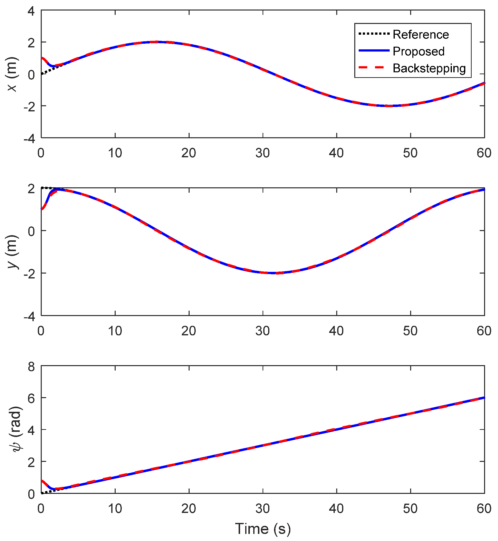
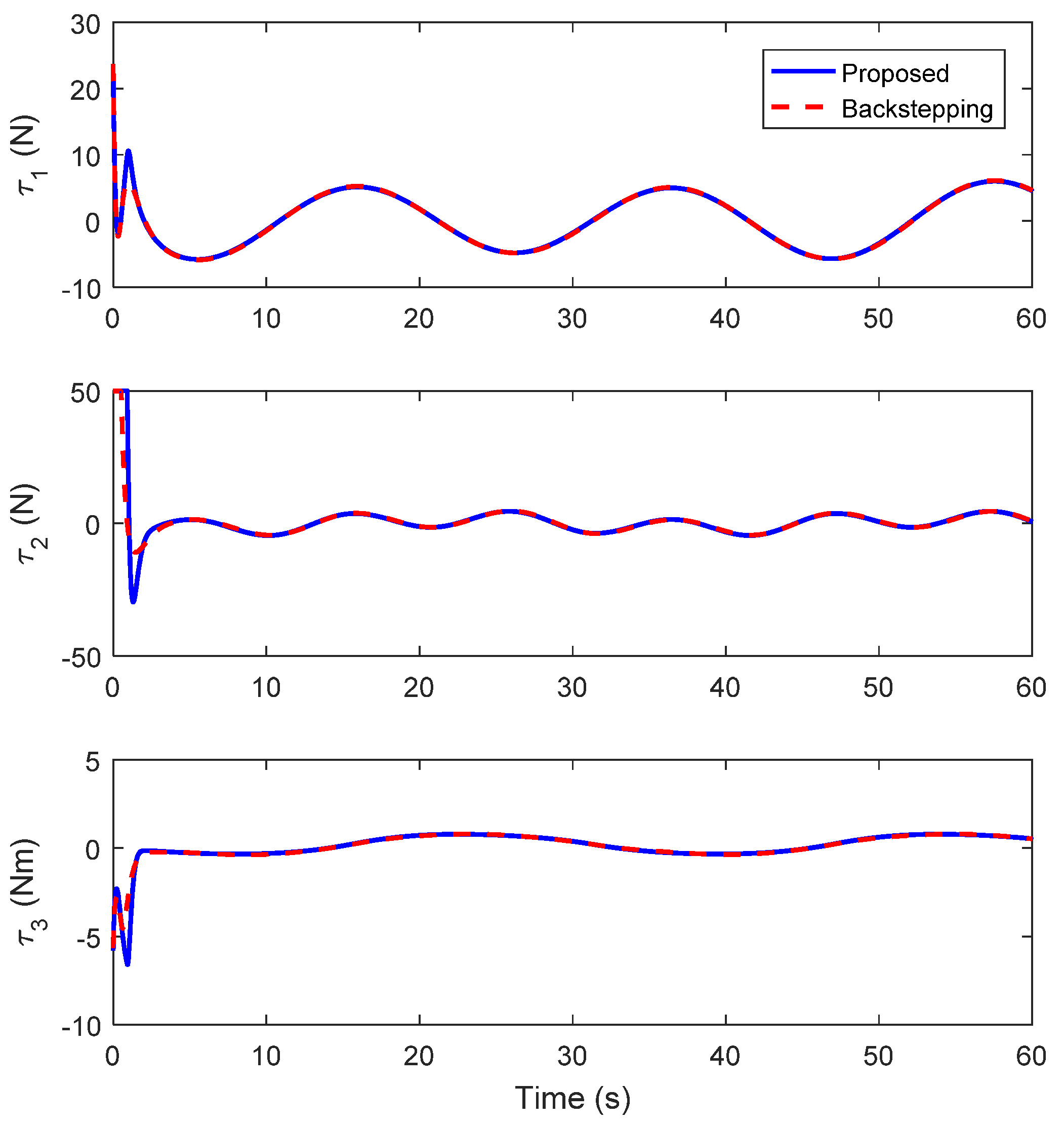
4.1. Circular Trajectory Tracking

In Case 1, the USV is expected to track a circular trajectory. The desired trajectory was set as η d = [ 2 sin ( 0.1 t ) , 2 cos ( 0.1 t ) , 0.1 t ] T . The initial position and velocity of the USV were chosen as η 0 = [ 1 , 1 , π / 4 ] T and υ 0 = [ 0 , 0 , 0 ] T .
Besides the proposed disturbance attenuation controller (26), the traditional backstepping controller (39), which was originally designed in [9], was also used for comparisons. The parameters of the proposed controller were selected as k 1 = 1 , k 2 = 6 , h 1 = 4 , and h 2 = 4 . For fair comparisons, the parameters that both controllers share were selected with the same values. Keeping this in mind, the parameters of the traditional backstepping controller were selected as k 1 = 1 and k 2 = 6 .
The simulation results of Case 1 are provided in Figure 3, Figure 4, Figure 5, Figure 6, Figure 7, Figure 8, Figure 9 and Figure 10. Figure 3 shows the planar trajectory tracking of the USV. The time profiles of the position and velocity tracking are given in Figure 4 and Figure 5, respectively. It is desirable that both controllers can accomplish the trajectory tracking task successfully. In particular, Figure 6 and Figure 7 present the time profiles of the position and velocity tracking errors, respectively. Obviously, the position and velocity steady-state errors under the traditional backstepping controller were much larger than those under the proposed controller. Therefore, the proposed controller can acquire superior tracking performance compared to the traditional backstepping controller. Owing to the utilization of two disturbance observers, the proposed controller is robust against model uncertainties and external disturbances and insensitive to measurement biases. The time profile of the control inputs is depicted in Figure 8. The control inputs under both controllers can meet the input saturation constraints. Figure 9 shows the mismatched lumped disturbance and its estimation, and Figure 10 shows the matched lumped disturbance and its estimation. It is clear that the two disturbance observers are efficient in estimating the mismatched and matched lumped disturbances.

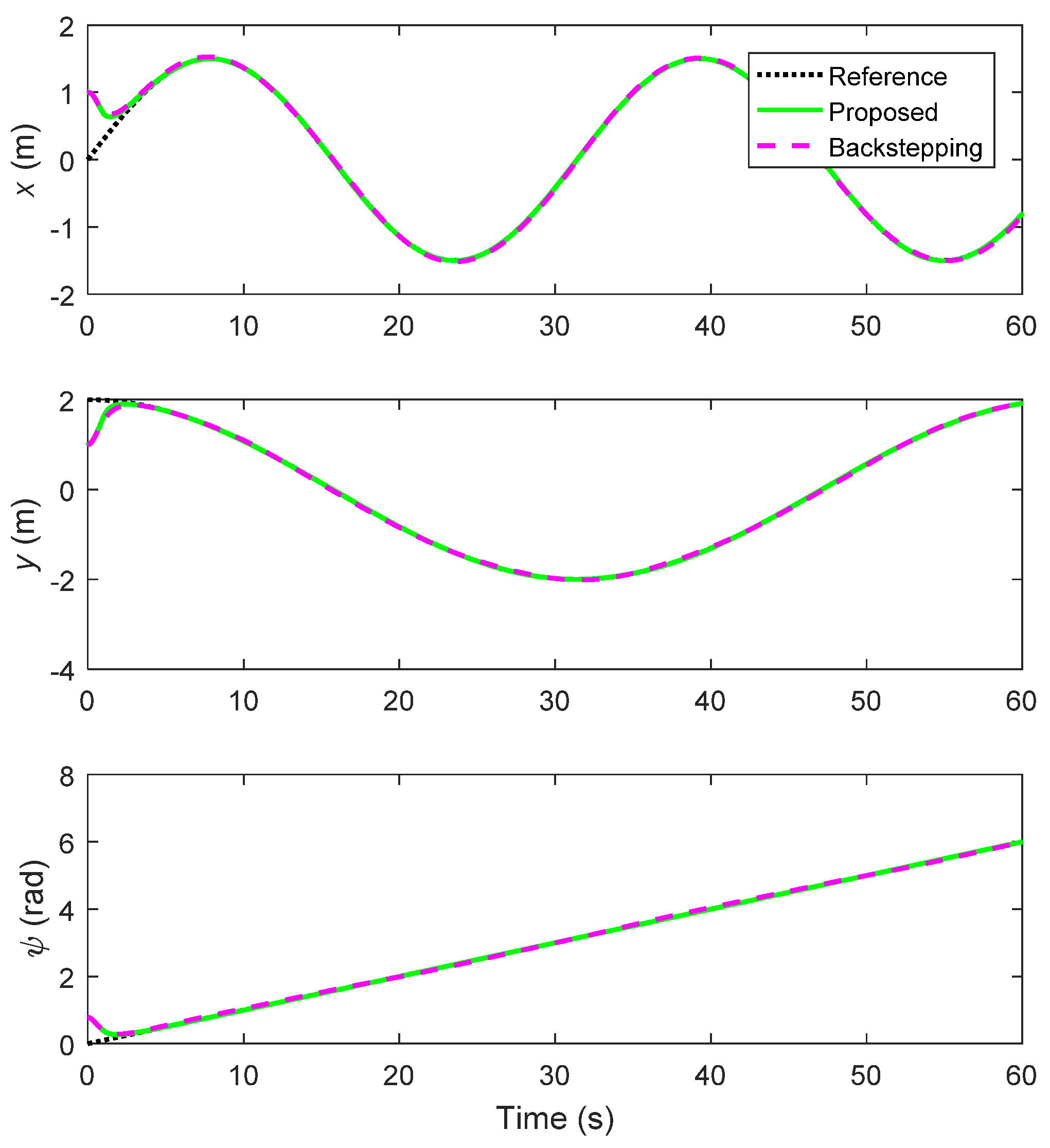
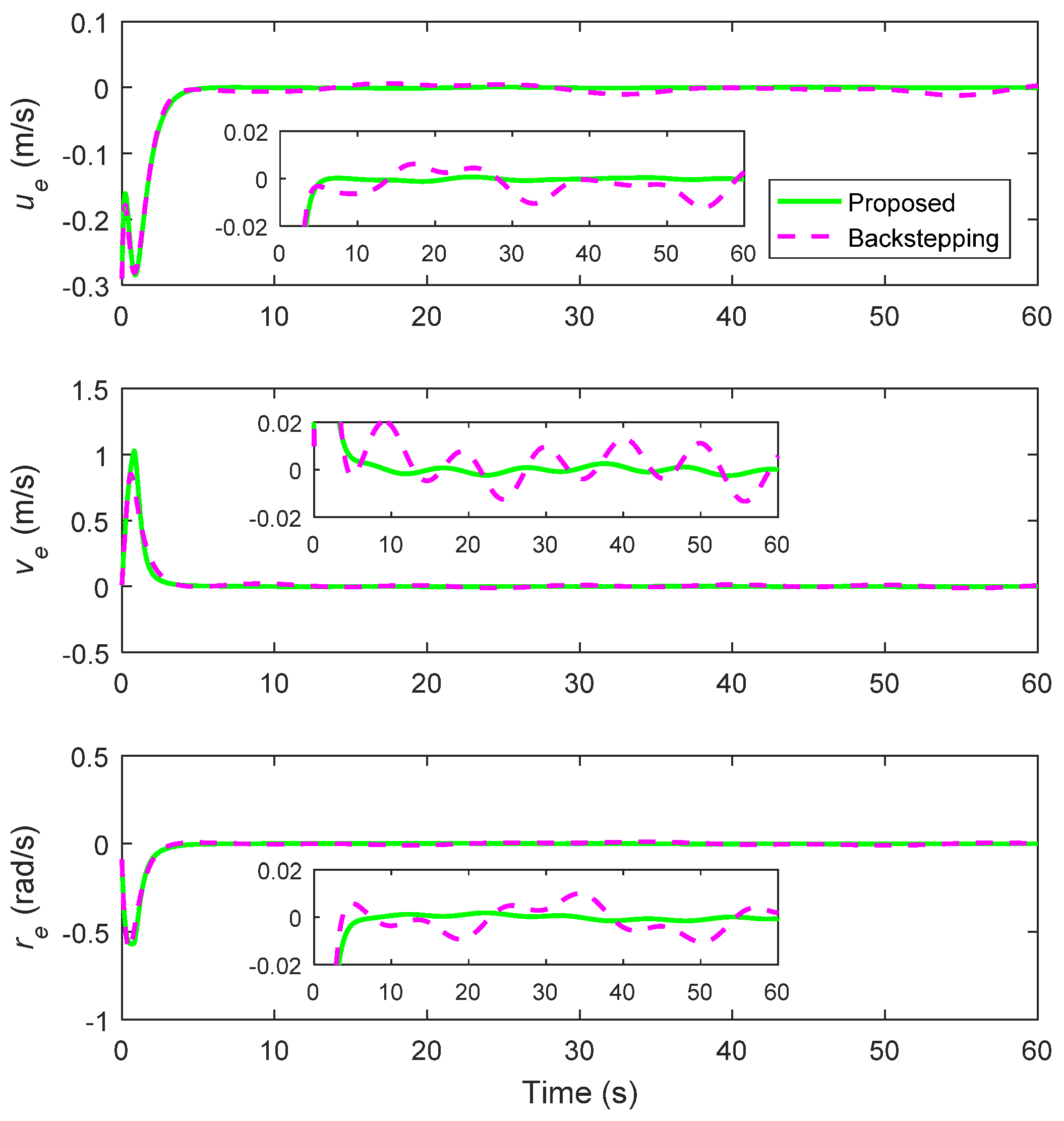
4.2. Lemniscate Trajectory Tracking

In Case 2, the USV was expected to track a lemniscate trajectory. The desired trajectory was set as η d = [ 1.5 sin ( 0.2 t ) , 2 cos ( 0.1 t ) , 0.1 t ] T . The initial position and velocity of the USV were chosen the same as those in Case 1. Moreover, the parameters of the proposed controller (26) and the traditional backstepping controller (39) were also selected the same as those in Case 1.
The simulation results of Case 2 are presented in Figure 11, Figure 12, Figure 13, Figure 14, Figure 15, Figure 16, Figure 17 and Figure 18. Likewise, the proposed controller can still fulfil the high-performance trajectory tracking in Case 2. Note that circle and lemniscate are two representative trajectories for the USV to be tracked in practice. The simulation results of Cases 1 and 2 indicate that the proposed controller is universal for tracking different types of reference trajectories and extremely suitable for practical engineering.

5. Conclusions

This article addresses the trajectory tracking control of USVs subject to position and velocity measurement biases by proposing a disturbance attenuation controller. The proposed controller was designed by integrating two disturbance observers under a backstepping control framework. The proposed controller can guarantee all error signals in the closed-loop system and regulate to the small neighborhoods about the origin. Lastly, the obtained results were validated through comparative simulations. In fact, relatively few existing studies have focused on the trajectory tracking control of USVs with the consideration of model uncertainties, external disturbances, and measurement biases simultaneously. The current work extends the relevant observer and controller designs in this field. Future research will focus on extending the proposed controller to the finite-time or fixed-time convergence scenarios.

Author Contributions

Conceptualization, Q.Y., H.J., C.L., A.A. and H.A.; methodology, Q.Y., H.J., C.L., A.A. and H.A.; validation, Q.Y., H.J., C.L., A.A. and H.A.; writing—original draft preparation, Q.Y., H.J., C.L., A.A. and H.A.; writing—review and editing, Q.Y., H.J., C.L., A.A. and H.A. All authors have read and agreed to the published version of the manuscript.

Funding

This research received no external funding.

Data Availability Statement

Not applicable.

Conflicts of Interest

The authors declare no conflict of interest.

References

  1. Liu, Z.; Zhang, Y.; Yu, X.; Yuan, C. Unmanned surface vehicles: An overview of developments and challenges. Annu. Rev. Control 2016, 41, 71–93. [Google Scholar] [CrossRef]
  2. Shi, Y.; Shen, C.; Fang, H.; Li, H. Advanced control in marine mechatronic systems: A survey. IEEE/ASME Trans. Mechatron. 2017, 22, 1121–1131. [Google Scholar] [CrossRef]
  3. Karimi, H.R.; Liu, Y. Guidance and control methodologies for marine vehicles: A survey. Control Eng. Pract. 2021, 111, 104785. [Google Scholar] [CrossRef]
  4. Su, Y.; Zheng, C.; Mercorelli, P. Nonlinear PD fault-tolerant control for dynamic positioning of ships with actuator constraints. IEEE/ASME Trans. Mechatron. 2017, 22, 1132–1142. [Google Scholar] [CrossRef]
  5. Mazenc, F.; Pettersen, K.; Nijmeijer, H. Global uniform asymptotic stabilization of an underactuated surface vessel. IEEE Trans. Autom. Control 2002, 47, 1759–1762. [Google Scholar] [CrossRef]
  6. Pettersen, K.Y.; Mazenc, F.; Nijmeijer, H. Global uniform asymptotic stabilization of an underactuated surface vessel: Experimental results. IEEE Trans. Control Syst. Technol. 2004, 12, 891–903. [Google Scholar] [CrossRef]
  7. Skjetne, R.; Fossen, T.I.; Kokotović, P.V. Adaptive maneuvering, with experiments, for a model ship in a marine control laboratory. Automatica 2005, 41, 289–298. [Google Scholar] [CrossRef]
  8. Ghommam, J.; Mnif, F.; Benali, A.; Derbel, N. Asymptotic backstepping stabilization of an underactuated surface vessel. IEEE Trans. Control Syst. Technol. 2006, 14, 1150–1157. [Google Scholar] [CrossRef]
  9. Yang, Y.; Du, J.; Liu, H.; Guo, C.; Abraham, A. A trajectory tracking robust controller of surface vessels with disturbance uncertainties. IEEE Trans. Control Syst. Technol. 2014, 22, 1511–1518. [Google Scholar] [CrossRef]
  10. Yin, S.; Xiao, B. Tracking control of surface ships with disturbance and uncertainties rejection capability. IEEE/ASME Trans. Mechatron. 2017, 22, 1154–1162. [Google Scholar] [CrossRef]
  11. Ashrafiuon, H.; Muske, K.P.; McNinch, L.C.; Soltan, R.A. Sliding-mode tracking control of surface vessels. IEEE Trans. Ind. Electron. 2008, 55, 4004–4012. [Google Scholar] [CrossRef]
  12. Wang, N.; Lv, S.; Zhang, W.; Liu, Z.; Er, M.J. Finite-time observer based accurate tracking control of a marine vehicle with complex unknowns. Ocean Eng. 2017, 145, 406–415. [Google Scholar] [CrossRef]
  13. Sun, Z.; Zhang, G.; Yang, J.; Zhang, W. Research on the sliding mode control for underactuated surface vessels via parameter estimation. Nonlinear Dyn. 2018, 91, 1163–1175. [Google Scholar] [CrossRef]
  14. Wang, N.; Karimi, H.R.; Li, H.; Su, S.-F. Accurate trajectory tracking of disturbed surface vehicles: A finite-time control approach. IEEE/ASME Trans. Mechatron. 2019, 24, 1064–1074. [Google Scholar] [CrossRef]
  15. Qiu, B.; Wang, G.; Fan, Y.; Mu, D.; Sun, X. Adaptive sliding mode trajectory tracking control for unmanned surface vehicle with modeling uncertainties and input saturation. Appl. Sci. 2019, 9, 1240. [Google Scholar] [CrossRef] [Green Version]
  16. Yao, Q. Adaptive finite-time sliding mode control design for finite-time fault-tolerant trajectory tracking of marine vehicles with input saturation. J. Franklin Inst. 2020, 357, 13593–13619. [Google Scholar] [CrossRef]
  17. Shen, Z.; Wang, Y.; Yu, H.; Guo, C. Finite-time adaptive tracking control of marine vehicles with complex unknowns and input saturation. Ocean Eng. 2020, 198, 106980. [Google Scholar] [CrossRef]
  18. Yao, Q. Fixed-time trajectory tracking control for unmanned surface vessels in the presence of model uncertainties and external disturbances. Int. J. Control 2022, 95, 1133–1143. [Google Scholar] [CrossRef]
  19. Weng, Y.; Wang, N. Finite-time observer-based model-free time-varying sliding-mode control of disturbed surface vessels. ISA Trans. 2022, 251, 110866. [Google Scholar] [CrossRef]
  20. Rodriguez, J.; Castañeda, H.; Gonzalez-Garcia, A.; Gordillo, J.L. Finite-time control for an unmanned surface vehicle based on adaptive sliding mode strategy. Ocean Eng. 2022, 254, 111255. [Google Scholar] [CrossRef]
  21. Pan, C.-Z.; Lai, X.-Z.; Yang, S.X.; Wu, M. An efficient neural network approach to tracking control of an autonomous surface vehicle with unknown dynamics. Expert Syst. Appl. 2013, 40, 1629–1635. [Google Scholar] [CrossRef]
  22. Wang, N.; Er, M.J. Self-constructing adaptive robust fuzzy neural tracking control of surface vehicles with uncertainties and unknown disturbances. IEEE Trans. Control Syst. Technol. 2015, 23, 991–1002. [Google Scholar] [CrossRef]
  23. Shojaei, K. Neural adaptive robust control for underactuated marine surface vehicles with input saturation. Appl. Ocean Res. 2015, 53, 267–278. [Google Scholar] [CrossRef]
  24. Wang, N.; Er, M.J. Direct adaptive fuzzy tracking control of marine vehicles with fully unknown parametric dynamics and uncertainties. IEEE Trans. Control Syst. Technol. 2016, 24, 1845–1852. [Google Scholar] [CrossRef]
  25. Wang, R.; Li, D.; Miao, K. Optimized radial basis function neural network based intelligent control algorithm of unmanned surface vehicles. J. Mar. Sci. Eng. 2020, 8, 210. [Google Scholar] [CrossRef] [Green Version]
  26. Deng, Y.; Zhang, X.; Im, N.; Zhang, G.; Zhang, Q. Adaptive fuzzy tracking control for underactuated surface vessels with unmodeled dynamics and input saturation. ISA Trans. 2020, 103, 52–62. [Google Scholar] [CrossRef]
  27. Wang, N.; Gao, Y.; Zhao, H.; Ahn, C.K. Reinforcement learning-based optimal tracking control of an unknown unmanned surface vehicle. IEEE Trans. Neural Netw. Learn. Syst. 2021, 32, 3034–3045. [Google Scholar] [CrossRef] [PubMed]
  28. Taghieh, A.; Zhang, C.; Alattas, K.A.; Bouteraa, Y.; Rathinasamy, S.; Mohammadzadeh, A. A predictive type-3 fuzzy control for underactuated surface vehicles. Ocean Eng. 2022, 266, 113014. [Google Scholar] [CrossRef]
  29. Fossen, T.I.; Grovlen, A. Nonlinear output feedback control of dynamically positioned ships using vectorial observer backstepping. IEEE Trans. Control Syst. Technol. 1998, 6, 121–128. [Google Scholar] [CrossRef]
  30. Tee, K.P.; Ge, S.S. Control of fully actuated ocean surface vessels using a class of feedforward approximators. IEEE Trans. Control Syst. Technol. 2006, 14, 750–756. [Google Scholar] [CrossRef]
  31. Wondergem, M.; Lefeber, E.; Pettersen, K.Y.; Nijmeijer, H. Output feedback tracking of ships. IEEE Trans. Control Syst. Technol. 2011, 19, 442–448. [Google Scholar] [CrossRef] [Green Version]
  32. Dai, S.-L.; Wang, M.; Wang, C.; Li, L. Learning from adaptive neural network output feedback control of uncertain ocean surface ship dynamics. Int. J. Adapt. Control Signal Process. 2014, 28, 341–365. [Google Scholar] [CrossRef]
  33. Park, B.S.; Kwon, J.-W.; Kim, H. Neural network-based output feedback control for reference tracking of underactuated surface vessels. Automatica 2017, 77, 353–359. [Google Scholar] [CrossRef]
  34. Hao, L.-Y.; Yu, Y.; Li, H. Fault tolerant control of UMV based on sliding mode output feedback. Appl. Math. Comput. 2019, 359, 433–455. [Google Scholar] [CrossRef]
  35. Zhang, C.; Wang, C.; Wang, J.; Li, C. Neuro-adaptive trajectory tracking control of underactuated autonomous surface vehicles with high-gain observer. Appl. Ocean Res. 2020, 97, 102051. [Google Scholar] [CrossRef]
  36. Zhang, C.; Wang, C.; Wei, Y.; Wang, J. Observer-based adaptive tracking control of underactuated autonomous marine vehicle with uncertainty dynamic. Appl. Ocean Res. 2020, 104, 102364. [Google Scholar] [CrossRef]
  37. Li, S.; Yang, J.; Chen, W.-H.; Chen, X. Generalized extended state observer based control for systems with mismatched uncertainties. IEEE Trans. Ind. Electron. 2012, 59, 4792–4802. [Google Scholar] [CrossRef] [Green Version]
  38. Yang, J.; Li, S.; Yu, X. Sliding-mode control for systems with mismatched uncertainties via a disturbance observer. IEEE Trans. Ind. Electron. 2013, 60, 160–169. [Google Scholar] [CrossRef]
  39. Yang, J.; Li, S.; Su, J.; Yu, X. Continuous nonsingular terminal sliding mode control for systems with mismatched disturbances. Automatica 2013, 49, 2287–2291. [Google Scholar] [CrossRef] [Green Version]
  40. Li, S.; Sun, H.; Yang, J.; Yu, X. Continuous finite-time output regulation for disturbed systems under mismatching condition. IEEE Trans. Autom. Control 2015, 60, 277–282. [Google Scholar] [CrossRef]
  41. Chen, W.-H.; Yang, J.; Guo, L.; Li, S. Disturbance-observer-based control and related methods–an overview. IEEE Trans. Ind. Electron. 2016, 63, 1083–1095. [Google Scholar] [CrossRef] [Green Version]
  42. Zhang, J.; Liu, X.; Xia, Y.; Zuo, Z.; Wang, Y. Disturbance observer-based integral sliding-mode control for systems with mismatched disturbances. IEEE Trans. Ind. Electron. 2016, 63, 7040–7048. [Google Scholar] [CrossRef]
  43. Yao, Q. Dual-disturbance-observer-based robust finite-time trajectory tracking control for robotic surface vehicle under measurement uncertainties. Ocean Eng. 2021, 242, 110183. [Google Scholar] [CrossRef]
  44. Fossen, T.I. Marine Control Systems: Guidance, Navigation, and Control of Ships, Rigs and Underwater Vehicles; Marine Cybernetics AS: Trondheim, Norway, 2002. [Google Scholar]
Figure 1. Planar motion of the USV.
Axioms 12 00361 g001
Figure 2. Structure of the proposed controller.
Axioms 12 00361 g002
Figure 3. Planar trajectory tracking of the USV (Case 1).
Axioms 12 00361 g003
Figure 4. Profile of the position tracking (Case 1).
Axioms 12 00361 g004
Figure 5. Profile of the velocity tracking (Case 1).
Axioms 12 00361 g005
Figure 6. Profile of the position tracking errors (Case 1).
Axioms 12 00361 g006
Figure 7. Profile of the velocity tracking errors (Case 1).
Axioms 12 00361 g007
Figure 8. Profile of the control inputs (Case 1).
Axioms 12 00361 g008
Figure 9. Mismatched lumped disturbance and estimation (Case 1).
Axioms 12 00361 g009
Figure 10. Matched lumped disturbance and estimation (Case 1).
Axioms 12 00361 g010
Figure 11. Planar trajectory tracking of the USV (Case 2).
Axioms 12 00361 g011
Figure 12. Profile of the position tracking (Case 2).
Axioms 12 00361 g012
Figure 13. Profile of the velocity tracking (Case 2).
Axioms 12 00361 g013
Figure 14. Profile of the position tracking errors (Case 2).
Axioms 12 00361 g014
Figure 15. Profile of the velocity tracking errors (Case 2).
Axioms 12 00361 g015
Figure 16. Profile of the control inputs (Case 2).
Axioms 12 00361 g016
Figure 17. Mismatched lumped disturbance and estimation (Case 2).
Axioms 12 00361 g017
Figure 18. Matched lumped disturbance and estimation (Case 2).
Axioms 12 00361 g018
Disclaimer/Publisher’s Note: The statements, opinions and data contained in all publications are solely those of the individual author(s) and contributor(s) and not of MDPI and/or the editor(s). MDPI and/or the editor(s) disclaim responsibility for any injury to people or property resulting from any ideas, methods, instructions or products referred to in the content.

