Article

Error Compensation of Strapdown Inertial Navigation System for the Boom-Type Roadheader under Complex Vibration

1
School of Mechanical Electronic and Information Engineering, China University of Mining & Technology, Beijing 100083, China
2
Shijiazhuang Coal Mine Machinery Co., Ltd., Shijiazhuang 051432, China
*
Author to whom correspondence should be addressed.
Axioms 2021, 10(3), 224; https://doi.org/10.3390/axioms10030224
Submission received: 11 August 2021 / Revised: 6 September 2021 / Accepted: 8 September 2021 / Published: 14 September 2021

Abstract

:
The strapdown inertial navigation system can provide the navigation information for the boom-type roadheader in the unmanned roadway tunneling working face of the coal mine. However, the complex vibration caused by the cutting process of the boom-type roadheader may result in significant errors of its attitude and position measured by the strapdown inertial navigation system. Thus, an error compensation method based on the vibration characteristics of the roadheader is proposed in this paper. In order to further analyze the angular and linear vibration of the fuselage, as the main vibration sources of the roadheader, the dynamic model of the roadheader is formulated based on the cutting load. Following that, multiple sub-samples compensation algorithms for the coning and sculling errors are constructed. Simulation experiments were carried out under different subsample compensation algorithms, different coal and rock characteristics, and different types of roadheader. The experimental results show that the proposed error compensation algorithm can eliminate the effect of the angular and linear vibration on the measurement accuracy. The coning and sculling error of the strapdown inertial navigation system can reduce at least 52.21% and 42.89%, respectively. Finally, a strapdown inertial navigation error compensation accuracy experiment system is built, and the validity and superiority of the method proposed in this paper are verified through calculation and analysis of the data collected on the actual tunneling work face.

1. Introduction

The International Energy Agency (IEA) points out that despite the growth of low-carbon emission fuels in recent decades, coal still dominates the global energy market. Today, the world’s coal consumption is 65% higher than that in 2000, and it still accounts for about 40% of the world’s power generation [1]. As the depth of coal mining continues to increase, the difficulty of coal mining also increases sharply [2]. Natural disasters such as high dust concentration, high ground temperature, and high rock pressure under deep conditions are more serious [3]. To achieve the safe and efficient mining of coal, the robotization of mining equipment has become a research hotspot in the field of unmanned mining. Roadway tunneling is the front part of coal mining. However, the unmanned roadway tunneling face has been developing slowly due to the narrow working space, cumbersome process flow, and complex environment [4,5,6]. The real-time perception of the position and attitude parameters of the roadheader in the process of cutting the coal wall is a key issue for realizing the unmanned tunneling face.
In cutting coal and rock, the roadheader is affected by many factors. The dislocation and attitude deviation of the whole machine will occur [7]. Furthermore, the position and attitude of the fuselage are constantly changing. Even more serious phenomena such as “sideslip” and “tail swing” appear, which seriously affects the directional tunneling of the roadheader, reduces the quality of roadway forming and tunneling efficiency [8]. Therefore, it is necessary to detect the position and attitude state of the roadheader during the cutting process, which will provide a parameter basis for the roadheader’s autonomous navigation and unmanned control. Fu et al. [9,10] proposed a detection system based on ultra-wideband technology and realized the continuous measurement of parameters of position and attitude of roadheader. Tao [11] used a fully automatic total station to detect the spatial position of multiple prisms installed on the fuselage to calculate the position and attitude of the roadheader in the roadway. Jia [12] applied the indoor positioning system (iGPS) to underground coal mines to realize the absolute position and attitude measurement of the roadheader. Du [13] realized the real-time measurement of the roadheader’s position and attitude based on the machine vision method. The above methods are carried out during the traveling or static state of the roadheader. However, in the cutting process, the cutting head rotates at high speed to cut the coal-rock wall, and the severe impact will drive the vibration of the fuselage. Moreover, the harsh environment of the roadway tunneling face, the poor light environment, and the serious dust suspension make the above methods subject to strong disturbances, so that accurate attitude and position parameters of the roadheader cannot be obtained.
Strapdown inertial navigation technology is based on Newton’s law of inertia to measure the attitude and position information of the carrier [14]. The strapdown inertial navigation system (SINS) does not need to interact with external information during the work process and is particularly suitable for the harsh working environment of the tunneling face. However, SINS is extremely sensitive to the vibration of the carrier, which will cause serious drifting of the mathematical platform, resulting in calculation errors and affecting measurement accuracy. Miller [15] proposed a three-subsample optimization algorithm for equivalent rotation vectors in a coning motion environment; On this basis, Musoff [16] proposed the optimization index of the coning compensation algorithm; Savage [17,18] has performed a systematic study on the error compensation of sculling motion effect and scrolling motion effect. These studies have a certain generality, the compensation for errors is only based on a single frequency, and it cannot achieve suitable results for complex mechanical vibrations in specific environments.
To precisely compensate for the calculation error of SINS in a specific vibration environment, it is necessary to obtain the accurate vibration form of the carrier. Yang [19] established the dynamic model of the double-drum shearer based on the force analysis of the shearer and compensated the SINS error according to the shearer’s vibration characteristics. Lai et al. [20] analyzed the unmanned aerial vehicle’s vibration environment and compensated for the coning error of SINS under the conditions of sinusoidal vibration and random vibration, respectively. During the cutting process of the roadheader, various forms of complex angular vibration and linear vibration appear on its body. To obtain its specific form, a dynamic analysis of the roadheader is required. Li et al. [21] used Lagrangian equations to derive the dynamic differential equation of the roadheader and obtained the mathematical model of the roadheader’s lateral and longitudinal vibration response. Hou [22] obtained the vibration form of the roadheader in three directions based on the dynamic analysis of the cutting head based on ADAMS software. Scholars’ research on the vibration response of roadheaders only involves linear vibration, but the angular vibration, which is serious interference of SINS precision, is rarely studied.
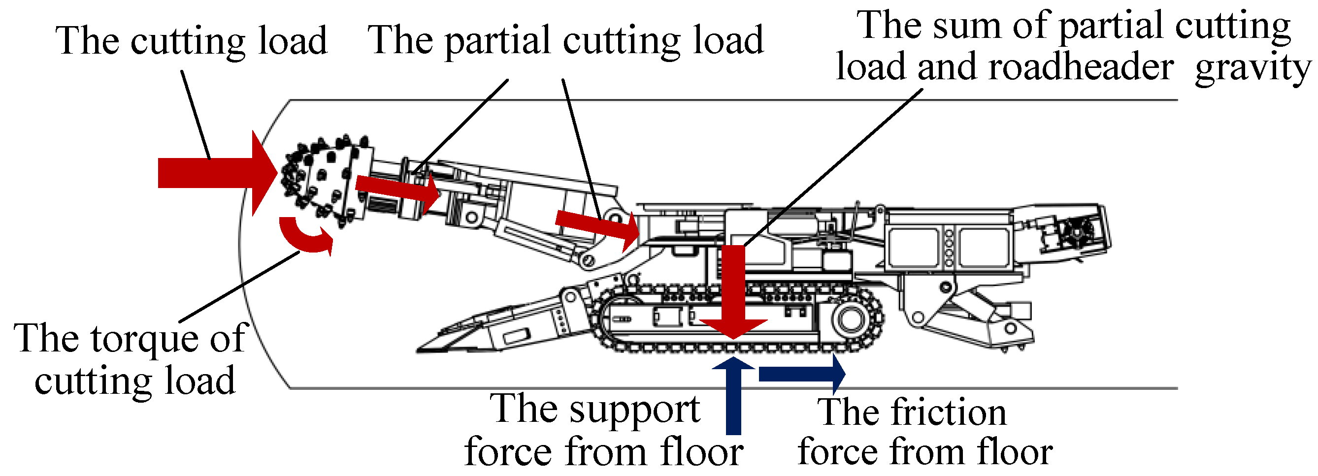
This paper proposes a compensation strategy for the SINS calculation error of the boom-type roadheader under a complex vibration environment. The force analysis of the roadheader and its cutting head is carried out, and a discrete calculation method is used to calculate its cutting load. On the above basis, the Lagrangian method is used to establish its dynamic model, and the characteristics of angular vibration and linear vibration are obtained. According to the angular vibration and linear vibration characteristics of the fuselage, multiple sub-samples compensation algorithms of the coning error and sculling error are constructed. The proposed SINS error compensation model is simulated and analyzed under different subsample compensation algorithms, different coal and rock characteristics, and different types of roadheaders, respectively. The main innovation of this paper is that through the force analysis of the roadheader and the construction of a multi-rigid body dynamic model, a multi-sample error compensation method of SINS based on the angular vibration and linear vibration of the roadheader body is proposed, which improves the accuracy of SINS applied to the roadheader in different situations.
The rest of this paper is organized as follows: In Section 2, the dynamics of the roadheader are analyzed, and the vibration form is obtained. Section 3 proposes the SINS calculation error compensation model. Simulation and analysis were carried out in Section 4. Conclusions are drawn in Section 5.

2. Dynamic Analysis of Roadheader

2.1. Force Analysis of Roadheader

The boom-type roadheader is the core equipment of the roadway tunneling face, as shown in Figure 1. It is mainly composed of a cutting head, cutting arm, fuselage, and walking mechanism. SINS is installed in an explosion-proof electric control box. The working principle of the roadheader is that the picks on the cutting head rely on the mechanical force generated by the rotation of the cutting head to act on the surface of the coal and rock mass so that the coal and rock blocks are peeled off from the coal wall of the roadway. Due to the complex and changeable storage conditions and physical and mechanical properties of coal and rock, the hardness of the coal and rock is constantly changing and has great randomness. The uncertainty of the hardness of coal and rock leads to complex and varied cutting loads of the cutting head. As shown in Figure 2, these variable cutting loads can be transmitted to the fuselage, which is the main vibration source of the roadheader. Therefore, to establish the dynamic model of the roadheader, it is necessary to analyze the force of the cutting head and calculate its cutting load.
The initial cutting process is that selecting a starting point on the cross-section of the roadway, then the roadheader moves, driving the cutting head to drill into the coal wall to a certain depth. Driven by the telescopic cylinder, the cutting head moves along the cutting path, as shown in Figure 3, until the cutting of the whole section is completed. When the cutting head cuts along the horizontal or vertical direction, the force conditions are similar, and all are subjected to cutting resistance, advancing resistance, and lateral resistance caused by part or all of the cutting load.
It can be seen from Figure 4 that when the cutting head is at a certain position, the i-th pick is subject to cutting resistance, advancing resistance P z i , and lateral resistance P x i . This paper adopts a cutting load discretization calculation method, which converts the sum of the cutting loads of all the picks participating in the cutting into the resultant force of the cutting head along the X, Y, and Z directions.
Force of the cutting head in X-direction:
R x = i = 1 D ( P z i cos ( φ i ) + P y i cos ( φ i ) )
Force of the cutting head in Y-direction:
R y = i = 1 D ( P z i sin ( φ i ) + P y i cos ( φ i ) )
Force of the cutting head in Z-direction:
R z = i = 1 D P x i
where D is the number of picks participating in the cutting, and φi is the position angle of the i-th pick.
The spirally distributed picks on the cutting head are subjected to a large dynamic load that is strong randomness during the cutting process. It is difficult to directly detect the load spectrum on the working face. To analyze the problem conveniently, the cutting load is regarded as a simple harmonic excitation force at a frequency of [ ω x   ω y   ω z ] in the X, Y, and Z directions, which is:
{ F x = R x sin ω x t F y = R y sin ω y t F z = R z sin ω z t

2.2. Dynamic Model of Roadheader

The boom-type roadheader is a huge and complicated mechanical structure system, coupled with the complicated working conditions of the tunneling face and the harsh working environment. To establish the dynamic model of the roadheader more reasonably, it is necessary to make assumptions and simplify the roadheader. The basic assumptions are as follows:
  • The mass distribution of each part of the roadheader is even, and the elasticity is minimal. It is simplified to concentrated mass m1, m 2 , and m3 (the mass of the cutting head, cutting arm, and fuselage, respectively). J represents the moment of inertia of the fuselage;
  • The parts of the roadheader are connected by massless elastic elements. The stiffness between the cutting head and the cutting arm, the cutting arm, and the fuselage, and the fuselage and the bottom floor are represented by k 1 , k2, k3, and k 4 , respectively;
  • The damping between each part of the roadheader is viscous damping. The damping between the cutting head and the cutting arm, the cutting arm, and the fuselage, and the fuselage and the bottom floor are represented by c1, c2, c3, and c4 respectively;
  • The roadheader operates normally, and there is no fault causing vibration of the roadheader.
The roadheader can be regarded as a completely dynamic system composed of three rigid bodies during the cutting process. As shown in Figure 5, the mechanical models of the roadheader in the X-direction, Y-direction, and Z-direction are established, respectively. For this multi-degree of freedom system, the Lagrange equation can be used to analyze the dynamic behavior of roadheader more accurately.
The Lagrangian equation of the system:
d d t ( T q ˙ s ) T q s + D q ˙ s + U q s = Q s
where Qs is the excitation force, qs is the generalized coordinate vector, T is the kinetic energy of the system, U is the potential energy of the system, and D is the dissipation energy of the system.
First, the vibration in the Z-direction of the vertical plane is analyzed, as shown in Figure 5a, and the motion equations of the roadheader for linear vibration and angular vibration are established. The generalized coordinate vectors q s = [ z 1 z 2 z 3 θ ] and q ˙ s = [ z ˙ 1 z ˙ 2 z ˙ 3 θ ˙ ] are defined as generalized displacement and generalized velocity, respectively, and it can be obtained that:
The kinetic energy of the roadheader in the Z-direction:
T = 1 2 m 1 z 1 2 + 1 2 m 2 z 2 2 + 1 2 m 3 z 3 2 + 1 2 J x θ ˙ 1 2
The elastic potential energy of the roadheader in the Z-direction:
U = 1 2 k 1 ( z 1 z 2 ) 2 + 1 2 k 2 ( z 2 z A ) 2 + 1 2 k 3 z A 2   + 1 2 k 4 z B 2 + 1 2 ( k 3 + k 4 ) ( a θ ) 2
The dissipated energy of the roadheader in the Z-direction:
D = 1 2 c 1 ( z ˙ 1 z ˙ 2 ) 2 + 1 2 c 2 ( z ˙ 2 z ˙ A ) 2 + 1 2 c 3 z ˙ A 2 + 1 2 c 4 z ˙ B 2 + 1 2 ( c 3 + c 4 ) ( a θ ˙ ) 2
where a and b are the dimensions of the fuselage, and according to the kinematic relationship, the following equation can be obtained: z A = z 3 a θ and z B = z 3 b θ .
Substituting the above relations (6), (7), and (8) into Lagrange’s Equation (5), we can get:
The linear vibration equation of the cutting head in the Z-direction:
m 1 z ¨ 1 + k 1 ( z 1 z 2 ) + c 1 ( z ˙ 1 z ˙ 2 ) = F z
The linear vibration equation of the cutting arm in the Z-direction:
m 2 z ¨ 2 + k 1 ( z 2 z 1 ) + k 2 ( z 2 z A ) + c 1 ( z ˙ 2 z ˙ 1 ) + c 2 ( z ˙ 2 z ˙ A ) = 0
The linear vibration equation of the fuselage in the Z-direction:
m 3 z ¨ 3 + k 2 ( z A z 2 ) + k 3 z A + k 4 z B   + c 2 ( z ˙ A z ˙ 2 ) + c 3 z ˙ A + c 4 z ˙ B = 0
The angular vibration equation of the fuselage in the Z-direction:
J θ ¨ + k 2 a ( z 2 z A ) k 3 a z A k 4 b z A + c 2 a ( z ˙ 2 z ˙ A ) c 3 a z ˙ A c 4 b z ˙ B = 0
Combine (9), (10), (11), and (12) to compose the vibration equation group of the roadheader in the Z-direction, which is the dynamic coupling model of the roadheader.

2.3. Solution to Dynamic Model of Roadheader

The dynamic coupling model of the roadheader in the process of cutting the coal wall in this paper is a complex system of multiple elements second-order differential dynamic equations, and it is difficult to obtain its analytical solution. To analyze and study the vibration form of the roadheader’s fuselage more intuitively, the numerical solution is obtained through MATLAB simulation. This paper takes the EBZ160-type boom-type roadheader as an example, and its parameters are brought into the dynamic model for simulation analysis. The linear vibration and angular vibration curves of the fuselage in the Z-direction are shown in Figure 6 and Figure 7, respectively.
It can be seen from the above figures that the vibration form of the linear vibration and angular vibration of the roadheader fuselage can be regarded as irregular, periodic fluctuations. The amplitude of the fuselage linear vibration in the Z-direction is between −0.18 and 0.19 m, and the amplitude of the fuselage angular vibration is between −1.9° and 1.9°. Based on the spectrum analysis of the above fuselage line vibration and angular vibration curves, the line vibration and angular vibration can be decomposed into the superposition of multiple sinusoidal components with different frequencies. This can be expressed as follows:
W d ( t ) = i = 1 m L i sin ( ω W i t + ε i ) + v W ( t )
A d ( t ) = i = 1 m M i sin ( ω A i t + φ i ) + v A ( t )
where W d ( t ) and A d ( t ) are the linear vibration and angular vibration of the roadheader fuselage, respectively. L i and Mi are the amplitudes of different frequency components of angular vibration and linear vibration, respectively. ω W i and ω A i are the angular velocities of different frequency components of linear vibration and angular vibration, respectively. εi and φi are the phase angle of different frequency components of linear vibration and angular vibration, respectively. vW(t) and vA(t) are the noise of angular vibration and line vibration, respectively. d = X, Y, and Z, respectively, represent the three directions of the coordinate axis.
The solving method of the dynamic model and vibration waveform of the roadheader in the X- and Y-directions are similar to that of the Z-direction, so the solution process of the roadheader fuselage in the X- and Y-directions are omitted here.

3. Errors Compensation for Roadheader SINS

The angular vibration and linear vibration of the carrier will cause the calculation error of SINS, which is also the main factor affecting the precision of SINS. The angular vibration will cause a coning error that affects the calculation of the attitude update. The angular vibration and linear vibration will cause sculling errors, affecting the calculation of velocity update. Next, based on the specific vibration form of roadheader obtained above, the compensation algorithms of coning error and sculling error are studied.

3.1. Calculation Error Compensation for Angular Vibration

Set the body coordinate frame of the roadheader as b-frame and the navigation coordinate frame as n-frame. A quaternion is a hypercomplex number composed of a real unit and three imaginary units. It contains four elements, and its definition expression is as follows
Q ( q 0 , q 1 , q 2 , q 3 ) = q 0 + q 2 i + q 2 j + q 3 k
where q 0 ,   q 1 ,   q 2 ,   q 3 are the real numbers, i, j, k are unit vectors that are orthogonal to each other.
It can contain all the information describing the rotation of a rigid body on a fixed axis, including the rotation direction and angle. In this paper, it can be considered that the vibration of the fuselage at a certain time is formed by the equivalent rotation of the n-frame to the b-frame without an intermediate process, so the quaternion can be used to describe the sinusoidal angle vibration of the roadheader. Set the unit directional vector of angular vibration to be μ = [ sin α cos β   cos α cos β   sin β ] where α and β are the half-cone angles of the directional vectors.
From the quaternion definition expression (15), the quaternion of the roadheader fuselage in a certain direction can be expressed as
Q ( t ) = [ cos ( W j ( t ) ) μ T sin ( W j ( t ) ) ]
The differential equation form of vibration quaternion is expressed as
Q ˙ ( t ) = Q ( t ) ω n b b ( t ) / 2
The angular velocity from the carrier n-frame to the b-frame are as follows
ω n b b ( t ) = 2 Q * ( t ) Q ˙ ( t ) = [ sin α cos β ( W ˙ j b ( t ) ) cos α cos β ( W ˙ j b ( t ) ) sin β ( W ˙ j b ( t ) ) ]
where Q(t) is the conjugate form of Q(t).
Assuming that the attitude update quaternion in an attitude update cycle T = tmtm−1 is q n b ( T ) , the attitude quaternion between time tm−1 and time t m is Q ( t m ) , as follows
Q ( t m ) = Q ( t m 1 ) q n b ( T )
The attitude update quaternion can be obtained as shown in (19)
q n b ( T ) = Q * ( t m 1 ) Q ( t m )
Assuming that the equivalent rotation vector corresponding to the attitude update quaternion q n b ( T ) changes in time period [ t m 1 , t m ] is ϕ ( T ) . From the relationship between the equivalent rotation vector ϕ ( T ) and the attitude update quaternion q n b ( T ) , we can get
q n b ( T ) = cos ϕ ( T ) 2 + ϕ ( T ) ϕ ( T ) sin ϕ ( T ) 2
where ϕ ( T ) = | ϕ ( T ) | is the modulus, and since ϕ ( T ) is a small quantity, sin ( ϕ ( T ) / 2 ) / ϕ ( T ) can be approximated to 1/2.
Therefore, the equivalent rotation vector ϕ ( T ) is
ϕ ( T )   = [ 2 sin α cos β ( i = 1 m L i sin ( ω W i T 2 ) cos ( ω W i t m 1 + ω W i T 2 ) ) 2 cos α cos β ( i = 1 m L i sin ( ω W i T 2 ) cos ( ω W i t m 1 + ω W i T 2 ) ) 2 sin β ( i = 1 m L i sin ( ω W i T 2 ) cos ( ω W i t m 1 + ω W i T 2 ) ) ]
Integrate the angular velocity (19) to obtain the angular increment in the equivalent rotation vector calculation time period [ t m 1 , t m ] :
Δ θ T = t m 1 t m ω n b b ( t ) d t = [ sin α cos β ( i = 1 s L i sin ( ω W i T 2 ) cos ( ω W i t m 1 + ω W i T 2 ) )   cos α cos β ( i = 1 s L i sin ( ω W i T 2 ) cos ( ω W i t m 1 + ω W i T 2 ) ) sin β ( i = 1 s L i sin ( ω W i T 2 ) cos ( ω W i t m 1 + ω W i T 2 ) ) ]
where s is the ratio of gyro bandwidth and frequency of vibration.
Comparing (22) and (23), it can be seen that errors will occur when the angular increment is used to replace the rotation vector, and the errors will continue to accumulate over time. Define the error as follows
δ ϕ T = ϕ ( T ) Δ θ T
To compensate for this error, a multi-sample compensation algorithm is usually used. N samples are taken in time period [ t m 1 , t m ] , and the sampling interval is recorded as h = T / N . According to (23), the angle increment in each sampling interval can be calculated as
Δ θ h ( i ) = t m 1 + ( i 1 ) h t m 1 + i h ω n b b ( t ) d t = [ 2 sin α cos β ( i = 1 s L i sin ω W i h 2 cos ( ω W i ( t m 1 + i h h / 2 ) ) )   2 cos α cos β ( i = 1 s L i sin ω W i h 2 cos ( ω W i ( t m 1 + i h h / 2 ) ) ) 2 sin β ( i = 1 s L i sin ω W i h 2 cos ( ω W i ( t m 1 + i h h / 2 ) ) ) ]
Under vibration conditions, the cross product between different sub-samples in (25) can compensate for the angle increment to a certain extent [23]. Therefore, the sum of the cross product between all sub-samples in time period [tm−1,tm] is generally used to estimate and compensate (24), denoted as
δ ϕ m = i = 1 N 1 k N i Δ θ ( i ) × Δ θ ( N )
where k is the coning error compensation coefficient. Table 1 gives the error compensation coefficient of the 1–5 subsample algorithm [24].

3.2. Calculation Error Compensation for Linear Vibration

When the cutting head cuts the coal wall, the SINS on the roadheader fuselage is in a state of angle vibration and linear vibration. When the roadheader makes linear vibration along the longitudinal axis of the fuselage and the same frequency and same phase angle vibration along the horizontal axis, there is velocity rectification in the vertical axis, which is the compensation term of the sculling effect. According to the error equation of sculling effect [24], it can be obtained that:
Δ v s c u l ( m ) b ( m 1 ) = 1 2 t m 1 t m θ i b b ( t , t m 1 ) × f s f b ( t ) + v s f b ( t , t m 1 ) × ω i b b ( t ) d t      = 1 2 t m 1 t m [ θ i b b ( t , t m 1 ) + v s f b ( t , t m 1 ) ] × [ f s f b ( t ) + ω i b b ( t ) ] d t
where θ i b b ( t , t m 1 ) is the angular vibration vector, and ω i b b ( t ) is the angular velocity vector, which can be obtained by (13):
θ i b b ( t , t m 1 ) = [ W d b ( t ) 0 0 ]
ω i b b ( t ) = θ ˙ i b b ( t , t m 1 ) = [ W ˙ d b ( t ) 0 0 ]
The v s f b ( t , t m 1 ) is the velocity vector, and the f s f b ( t ) is the acceleration vector. From (16), it can be obtained that:
v s f b ( t , t m 1 ) = [ 0 A ˙ d b ( t ) 0 ]
f s f b ( t ) = v ˙ s f b ( t , t m 1 ) = [ 0 A ¨ d b ( t ) 0 ]
Similar to the coning error compensation Formula (26), the multi-subsample compensation algorithm is also used to compensate for the sculling errors. Performing N samplings in time period [tm−1, tm], the angle increment and velocity increment of each sampling interval can be calculated as:
Δ θ m i = 1 2 t m 1 + ( i 1 ) h t m 1 + i h ω i b b ( t ) d t
Δ v m i = 1 2 t m 1 + ( i 1 ) h t m 1 + i h f i f b ( t ) d t
Substituting (32) and (33) into the error equation of sculling effect (28), the following equation can be obtained:
Δ v ^ s c u l ( m ) b ( m 1 )       = i = 1 N 1 k s N i ( Δ θ m i + Δ v m i ) × ( Δ θ m N + Δ v m N )
where Δ θ m N is the increment of angular vibration in time period [ t m 1 , t m ] , Δ v m N is the increment of linear vibration velocity in time period [ t m 1 , t m ] , and ks is the sculling error compensation coefficient.
Let U m i = Δ θ m i + Δ v m i and U m N = Δ θ m N + Δ v m N . Substitute it into (34), and get
Δ v ^ s c u l ( m ) b ( m 1 )   = i = 1 N 1 k N i U m i × U m N
The Formula (35) is identical to the coning error compensation Formula (26) in form, so the coning error compensation coefficients can be applied to the sculling error compensation algorithm. Meanwhile, notice that Δ θ m i × Δ θ m N = Δ v m i × Δ v m N = 0 in the sculling motion.
Therefore, the above formula can be expanded to
Δ v ^ s c u l ( m ) b ( m 1 )   = i = 1 N 1 k N i U m i × U m N
where kN−i is the cone error compensation coefficient; see Table 1.

4. Simulation and Analysis for Compensation Algorithms

4.1. Simulation for Calculation Error Using Multi-Samples Compensation Algorithms

To verify the compensation effect of the method proposed in this paper on the linear vibration error and angular vibration error of the SINS in the process of cutting the coal wall of the boom-type roadheader, one-subsample, three-subsample, and four-subsample compensation algorithms were used for simulation and analysis, respectively. The vibration of the roadheader is highly arbitrary, and the changes are complex. It can be known from the third part of this paper that it is only an approximate method to fit the vibration of the roadheader with a certain curve during the update cycle. In view of the fact that the large calculation burden affects the real-time of the roadheader’s position and attitude parameter perception, the three-subsample and four-subsample compensation algorithms are selected for comparison and analysis, and the one-subsample algorithm (without compensation) is used as a reference.
This simulation takes the EBZ-160 type boom-type roadheader as an example. In the process of cutting the coal wall horizontally of the roadheader, when the vertical swing angle of the cutting arm is 8°, and the inclination angle of the coal seam is 10°, the swing speed of the cutting arm is 0.1 m/s, the rotational speed of the cutting head is 46 r/min, and the force amplitude is 80 kN. Take FOSN-type fiber SINS produced by China Aerospace Science and Industry Corporation Limited as an example, and its basic parameters are: the constant drift of the fiber-optic gyroscope is 0.01°/h, and the random drift is 0.005°/h; the constant drift of the quartz accelerometer is 30 μg, and the random drift is 30 μg; the data sampling frequency is 100 Hz. The simulation location is 116°20′ east longitude and 39°56′ north latitude. The local acceleration of gravity is g = 9.82840944   m / s 2 ; the radius of curvature of the meridian is RM = 6,361,840.46 m; the radius of curvature of the prime vertical is R N = 6,397,829.93   m ; and the angular velocity of the earth rotation is ω e = 7.292115 × 10 5   rad / s . The simulation lasts for 150 s.
Figure 8 shows the coning error curves of SINS with the compensation algorithm of one-subsample (OS), three-subsample (TS), and four-subsample (FS) during the roadheader cutting the coal wall horizontally: (a) is the error curve in X-direction, (b) is the error curve in Y-direction, (c) is the error curve in Z-direction. It can be seen from the figures that the error curves of the three compensation algorithms all vary periodically over time, and there are slight changes in a single period. Compared with the one-subsample algorithm, the improvement of compensation accuracy of the three-subsample and four-subsample compensation algorithm is more obvious. The compensation accuracy between the three-subsample and the four-subsample is relatively close. Since the one-sample compensation algorithm replaces the equivalent rotation vector by the angular increment directly, the third-sample and fourth-sample compensation algorithms use quadratic function and cubic function, respectively, to fit the equivalent rotation vector, which can effectively reduce the non-commutativity error.
The statistical properties of the simulation results of the coning error are shown in Table 2. As the number of compensation sub-samples increases, the statistical values of the angular vibration error are all decreasing. The accuracy of the four-subsample algorithm is slightly improved compared with the three-subsample algorithm, while the calculation amount of the four-subsample algorithm is more than that of the three-subsample algorithm. The maximum values of the coning error in the X -direction, Y-direction, and Z-direction with the three-subsample compensation algorithms are 2.9909 × 10 4   °, 0.0019°, and 2.7194 × 10 4   °, respectively. It meets the accuracy requirements of the attitude and position detection of the roadheader. Therefore, it is more appropriate to use the three-sample compensation algorithm to compensate the angular vibration error of the SINS in the process of cutting the coal wall by the roadheader.
Figure 9 shows the sculling error curves of SINS with the compensation algorithms of one-subsample (OS), three-subsample (TS), and four-subsample (FS) during the roadheader is cutting the coal wall horizontally: (a) is the error curve in X-direction, (b) is the error curve in Y-direction, (c) is the error curve in Z-direction. It can be seen that the trend of the error curves of the roadheader SINS in those three directions with each subsample compensation algorithm is similar. As the number of sub-samples of the compensation algorithm increases, the amplitude of the linear vibration error decreases accordingly. The compensation effect of the three-subsample and the four-subsample algorithms are better than that of the one-subsample. The accuracy of the linear vibration error of the four-subsample is not significantly improved compared with the three-subsample. The statistical properties of the simulation results of the sculling error are shown in Table 3. According to the above analysis of the coning error, comparing the one-subsample compensation algorithm with the three-subsample compensation algorithm, it can be obtained that the compensation accuracy of the three-subsample compensation algorithm relative to the one-subsample compensation algorithm is improved by 42.89% in the X-direction, 46.65% in the Y-direction, and 60.00% in the Z-direction.

4.2. Simulation for Calculation Error under Different Coal and Rock Characteristics

The coal wall contains gangue and hard inclusions with different compositions. Their contents, shapes, physical and mechanical properties are different. In addition, there are cracks in the coal structure, such as bedding and joints, so the properties of the coal wall are different. These natural factors make the cutting head of the roadheader bear the influence of varying loads in the process of coal breaking. From the analysis of Section 2, it can be seen that the vibration characteristics of roadheader under different cutting loads are different, so it has important significance for the SINS calculation error analysis of roadheader under different coal and rock characteristics. The composition of the coal wall is roughly divided into three categories: coal, coal-gangue (the mixture of coal and gangue), and gangue. To analyze the error compensation characteristics of the roadheader when cutting coal walls with different compositions, simulation experiments were carried out under these three types of working environments.
Setting the roadheader to cut horizontally, the vertical swing angle of the cutting arm is 8°, the roadway inclination is 10°, the swing speed of the cutting arm is 0.1 m/s, and the speed of the cutting head is 46 r/min. As the hardness of coal, coal-gangue, and gangue increased successively, the reaction force on the cutting head during the cutting process also increases. According to the relationship between coal hardness coefficient and cutting force, the force amplitude of the cutting head is set to 80, 90, and 110 kN, respectively.
Other conditions are the same as simulation 4.1. The simulation results are shown in Figure 10 and Figure 11.
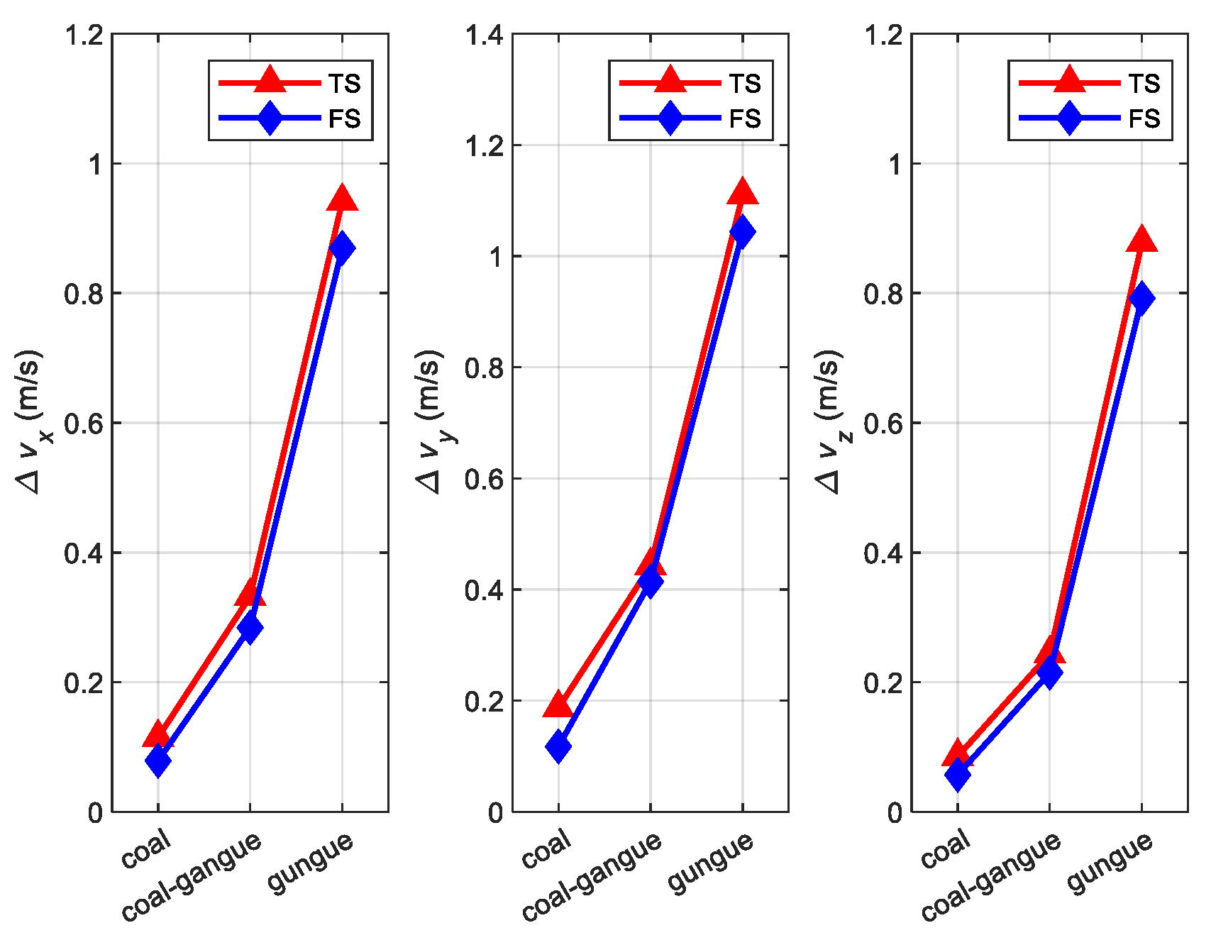
Figure 10 is the coning error statistics using the three-subsample (TS) compensation algorithm and four-subsample (FS) compensation algorithm under different coal and rock characteristics. Figure 11 is the sculling error statistics using the three-subsample (TS) compensation algorithm and four-subsample (FS) compensation algorithm under different coal and rock characteristics. Both the coning error and the sculling error of the SINS vary with the vary of coal-rock characteristics and increase with the increase in coal-rock hardness. The error of cutting coal is the smallest, and the error of cutting gangue is the largest. Meanwhile, the increased amplitude of SINS error when roadheader cutting coal-gangue is nearly twice as high as when cutting gangue. The SINS error of the four-subsample compensation algorithm is slightly smaller than that of the three-subsample compensation algorithm.

4.3. Simulation for Calculation Error under Different Types of Roadheaders

For different types of roadheaders, the technical parameters such as the rated cutting power, the mass of the fuselage, and the external dimensions are different. The corresponding stiffness and damping coefficients are different, which results in different dynamic vibration characteristics of the roadheader. To analyze the vibration error of the roadheader SINS under different vibration characteristics, three types of roadheaders(EBZ160, EBZ260, and EBZ320) were selected as the research objects. The technical parameters of these three types of roadheader are, respectively, introduced into the dynamic model of roadheader established in Section 2 above to obtain its dynamic characteristics, as shown in Table 4. Based on this, the simulation experiments of angular vibration error and linear vibration of roadheader are carried out. Other conditions are the same as simulation 4.1. The simulation results are shown in Figure 12 and Figure 13.
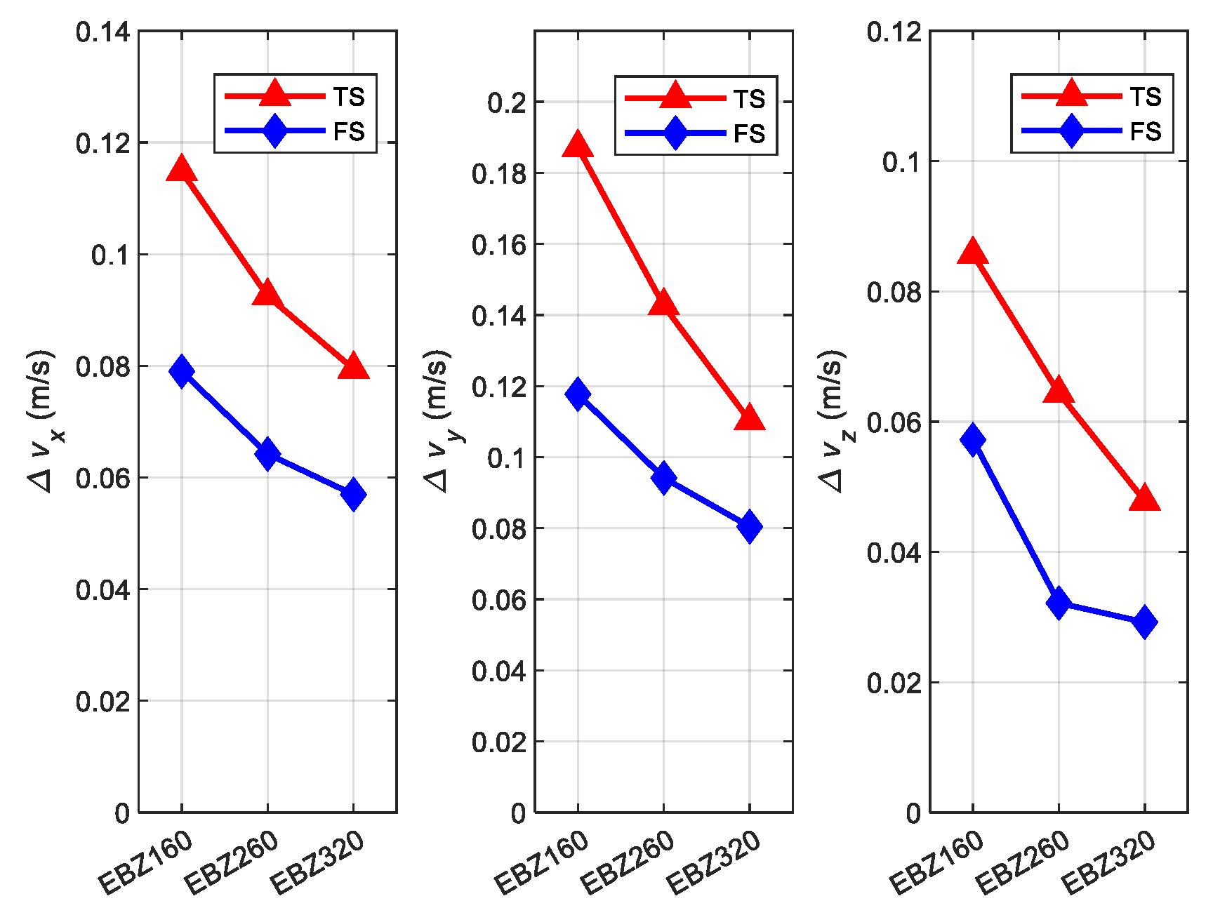
Figure 12 is the coning error statistics using the three-subsample (TS) compensation algorithm and four-subsample (FS) compensation algorithm under different types of roadheaders. Figure 13 is the sculling error statistics using the three-subsample (TS) compensation algorithm and four-subsample (FS) compensation algorithm under different types of roadheaders. It can be seen from the two figures that the coning error and sculling error of the EBZ160-type roadheader are the lowest, while the coning error and sculling error of the EBZ320-type roadheader are the highest. With the increase in the rated cutting power of the roadheader, their coning error and sculling error are decreasing. The roadheader with large cutting power has a strong ability to withstand disturbances under the same external excitation, and its fuselage vibration frequency is smaller under the same external excitation. For the coning error and sculling error of the three types of roadheaders, the compensation effects of the three-subsample compensation algorithm and the four-subsample compensation algorithm are similar. Considering that the four-sample algorithm will greatly increase the computational burden, the three-sample compensation algorithm is applicable to all three kinds of roadheader. However, for the sculling error of the EBZ260-type roadheader in three directions, the compensation effect of the four-sample compensation algorithm is significantly improved than that of the three-subsample compensation algorithm, so the four-sample compensation algorithm is given priority when the system computing capacity allows.

5. Experiment

5.1. Experiment Scheme

To verify the effectiveness of the method proposed in this paper, a SINS error compensation accuracy experiment system was built. The original data of SINS output during the cutting process were collected in the tunneling face of the coal mine, and the compensation algorithm proposed in this paper was used to analyze the coning error and sculling error. The composition of the experimental system is shown in Figure 14, which consists of an EBZ160 roadheader, an optical fiber SINS, and a navigation host. The basic parameters of fiber-optic SINS are shown in Table 5. Due to the explosion-proof requirements for instruments in underground coal mines, in the actual acquisition process, SINS is installed in an explosion-proof box fixed at the center of the upper part of the roadheader’s fuselage and powered by the internal power supply of the roadheader; the navigation host is placed in the control cabin that installed in roadway chamber, connected with SINS via network cable. The baud rate is 115,200 bit/s, and the sampling frequency is 100 Hz.
Drive the roadheader to the front of the cutting section of the roadway and complete the initial cutting, then perform an initial alignment for 5 min, and set the current position as the initial position P 0 ( 0 , 0 , 0 ) , the initial velocity is V 0 ( 0 , 0 , 0 ) . Control the cutting arm swings to make the cutting head cut a certain distance in the transverse direction and then cut a certain distance in the longitudinal direction, and save the original output of the three-axis fiber-optic gyroscope and three-axis accelerometer in the SINS during the whole process. The experiment was carried out 5 times.

5.2. Experiment Results

The 5 serials original data collected are used to analyze the compensation accuracy of the coning error and sculling error of SINS using the error compensation method proposed in this paper. It is calculated using one-subsample (without compensation, as a comparison), three-subsample, and four-subsample compensation algorithms, and the results are shown in Figure 15 and Figure 16. Figure 15 shows the coning error of SINS in X, Y, and Z directions, Figure 16 shows the sculling error of SINS in X, Y, and Z directions. It can be concluded that, in the 5 experiments, compared with the case of no compensation, both the three-subsample and four-subsample algorithms greatly reduce the coning error and sculling error. The coning error in X, Y, and Z directions is reduced by 51.00%, 36.13%, and 44.16%, respectively, and the sculling error is reduced by 55.72%, 36.47%, and 44.49%, respectively. Furthermore, the four-subsample algorithm is better than the three-subsample algorithm. Compared with the three-subsample algorithm, the coning error of the four-subsample algorithm is reduced by 24.86%, 16.95%, and 14.26% in the X, Y, and Z directions, respectively; the sculling errors were reduced by 27.61%, 16.99%, and 20.85%, respectively. It fully proves the effectiveness and superiority of the method proposed in this paper.

6. Conclusions

Aiming at the problem that the complex vibration generated by the roadheader in the process of cutting the coal wall makes the SINS calculation error huge, this paper presents a method for compensation of the angle vibration error and linear vibration error of SINS based on the dynamic model of roadheader. By establishing the dynamic model of the roadheader, multiple sub-samples compensation algorithms for SINS coning error and sculling error based on the vibration characteristics of the roadheader fuselage are presented. Simulation experiments show that, compared to the one-subsample compensation algorithm, the three-subsample and four-subsample compensation algorithms have significantly improved compensation effect for coning and sculling errors, while the four-subsample compensation algorithm is slightly better than the three-subsample compensation algorithm; under the conditions of different coal and rock characteristics, the calculation error of SINS is the smallest when the roadheader is cutting coal, and the calculation error of SINS is the largest when the roadheader is cutting gangue; for different types of roadheader, the coning error and sculling error of roadheader SINS decrease with the increasing of rated cutting power. An experimental system of SINS error compensation accuracy experiment system was built. The calculation and analysis of the original data collected on the actual working face verified that this method has a suitable compensation effect for the calculation error of the roadheader SINS under complex vibration conditions. It has great significance for the development of the unmanned mining field.

Author Contributions

Conceptualization, Y.S.; methodology, Y.S. and H.J.; software, X.J.; validation, Y.S., P.W. and W.Z.; formal analysis, H.J.; resources, M.W.; data curation, W.Z.; writing—original draft preparation, Y.S.; writing—review and editing, Y.S.; visualization, W.Z.; supervision, M.W.; project administration, M.W.; funding acquisition, M.W. All authors have read and agreed to the published version of the manuscript.

Funding

This research was supported by the National Natural Science Foundation of China, grant number 51874308 and the APC was funded by National Natural Science Foundation of China.

Data Availability Statement

The data used to support the findings of this study are included within the article.

Acknowledgments

This research was supported by the National Natural Science Foundation of China, grant number 51874308.

Conflicts of Interest

The authors declare that they have no conflict of interest.

References

  1. IEA (International Energy Agency). Coal 2019 Analysis and Forecasts to 2024; IEA: Paris, France, 2019. [Google Scholar]
  2. He, A.H.; Li, Y.B. A brief discussion on the characteristics and prevention measures of geological disasters in coal mines. West-China Explor. Eng. 2010, 32, 165–166. [Google Scholar]
  3. Bai, Y.L.; Li, H.L.; Chen, Y.; Zhou, Q.; Bai, C.J.; Xi, L. Statistical Analysis of coal mine accident cases in China in 2019. Policy Res. Explor. 2020, 9, 17–18. [Google Scholar]
  4. Wang, G.F.; Wang, H.; Ren, H.W. 2025 scenarios and development path of intelligent coal mine. J. China Coal Soc. 2018, 43, 295–305. [Google Scholar]
  5. Ge, S.R. Present situation and development direction of coal mine robots. China Coal 2019, 45, 18–27. [Google Scholar]
  6. Yang, J.J.; Zhang, Q.; Wang, C.; Chang, B.S.; Wang, X.L.; Ge, S.R.; Wu, M. Status quo and development of robotization research of coal mine China Coal. J. China Coal Soc. 2020, 45, 2995–3005. [Google Scholar]
  7. Zong, K.; Zhang, P.; Wang, P.J.; Fu, S.; Zhang, M.; Wu, M. Multifactor Analysis of Roadheader’s Body Pose Responses during the Horizontal Cutting Process. Shock Vib. 2018, 2018, 2387408. [Google Scholar] [CrossRef] [Green Version]
  8. Zong, K.; Fu, S.C.; Li, Y.M. Analysis of Influence Regularity of Cutting Head Load to Roadheader’s Deviation Angle. Ind. Mine Autom. 2018, 44, 46–51. [Google Scholar]
  9. Fu, S.C. Research on Pose Detection Method of Boom-Type Roadheader Based on UWB Distance Measurement. Ph.D. Thesis, Mechanical Electronic and Information Engineering, China University of Mining & Technology (Beijing), Beijing, China, 2018. [Google Scholar]
  10. Fu, S.C.; Li, Y.M.; Zhang, M.J. Ultra-wideband pose detection system for boom-type roadheader based on Caffery transform and Taylor series expansion. Meas. Sci. Technol. 2017, 29, 015101. [Google Scholar] [CrossRef] [Green Version]
  11. Tao, Y.F. Research on Automatic Measurement Method and System of Position and Attitude of Roadheader Based on Laser Measurement System. Ph.D. Thesis, Mechanical Electronic and Information Engineering, China University of Mining & Technology (Beijing), Beijing, China, 2017. [Google Scholar]
  12. Tao, Y.F.; Zong, K.; Zhang, M.J. A position and orientation measurement method of single-station, multipoint and time-sharing for roadheader body based on iGPS. J. China Coal Soc. 2015, 40, 2611–2616. [Google Scholar]
  13. Du, Y.X.; Tong, M.M.; Liu, T.; Dong, H.B. Visual measurement system for roadheaders pose detection in mines. Opt. Eng. 2016, 55, 104107. [Google Scholar] [CrossRef]
  14. David, H.T.; John, L.W. Basic Principles of Strapdown Inertial Navigation Systems, in Strapdown Inertial Navigation Technology, 2nd ed.; The Institution of Electrical Engineers: Herts, UK, 2004; Chapter 2; pp. 17–25. [Google Scholar]
  15. Miller, R.B. A new strapdown attitude algorithm, Journal of Guidance. Control Dyn. 1983, 40, 287–291. [Google Scholar] [CrossRef]
  16. Musoff, H.; Murphy, J.H. Study of strapdown navigation attitude algorithms. J. Guid. Control Dyn. 1995, 28, 287–290. [Google Scholar] [CrossRef]
  17. Savage, P.G. Strapdown inertial navigation integration algorithm design part 1: Attitude algorithms. J. Guid. Control Dyn. 1998, 21, 19–28. [Google Scholar] [CrossRef]
  18. Savage, P.G. Strapdown inertial navigation integration algorithm design part 2: Velocity and position algorithms. J. Guid. Control Dyn. 1998, 21, 208–229. [Google Scholar] [CrossRef]
  19. Yang, H. Research on Accurate Position and Pose Perception Theory and Technology for Shearer with SINS/WSN Integrated Localization. Ph.D. Thesis, School of Mechatronic Engineering, China University of Mining and Technology, Xuzhou, China, 2016. [Google Scholar]
  20. Lai, J.; Lv, P.; Liu, J.; Jiang, B. Noncommutativity error analysis of strapdown inertial navigation system under the vibration in UAVs. Int. J. Adv. Robot. Syst. 2012, 9, 1–8. [Google Scholar] [CrossRef]
  21. Li, X.H.; He, Y.; Li, T.; Yu, T.T. Analysis of horizontal and vertical random vibration responses of longitudinal roadheader. J. China Coal Soc. 2014, 33, 1484–1488. [Google Scholar]
  22. Hou, X.M. The Analysis About the Load on Cutting Head and Vibration of Transverse Roadheader. Master’s Thesis, Department of Mechanical Engineering, AnHui University of Science and Technology, Huaian, China, 2008. [Google Scholar]
  23. Kang, C.W.; Cho, N.L.; Park, C.G. Approach to direct coning/sculling error compensation based on the sinusoidal modelling of IMU signal. IET Radar Sonar Navig. 2013, 7, 527–534. [Google Scholar] [CrossRef]
  24. Qin, Y.Y. Strapdown Inertial Navigation System. In Inertial Navigation, 2nd ed.; Science Press: Beijing, China, 2014; Chapter 7; pp. 259–298. [Google Scholar]
Figure 1. Schematic diagram for the roadheader (1—cutting head; 2—cutting arm; 3—coal wall; 4—walking mechanism; 5—SINS; 6—fuselage).
Axioms 10 00224 g001
Figure 2. Force analysis diagram of the roadheader.
Axioms 10 00224 g002
Figure 3. The cutting path of the cutting head.
Axioms 10 00224 g003
Figure 4. Force analysis diagram of cutting head.
Axioms 10 00224 g004
Figure 5. Mechanical model of roadheader. (a) Z-direction; (b) X-direction; (c) Y-direction.
Axioms 10 00224 g005
Figure 6. The curve of linear vibration of roadheader fuselage.
Axioms 10 00224 g006
Figure 7. The curve of line angular of roadheader.
Axioms 10 00224 g007
Figure 8. The coning error curve of SINS with the compensation algorithm of one-subsample (OS), three-subsample(TS), and four-subsample (FS): (a) the error curve in X-direction, (b) the error curve in Y-direction, (c) the error curve in Z-direction.
Axioms 10 00224 g008aAxioms 10 00224 g008b
Figure 9. The sculling error curve of SINS with the compensation algorithm of one-subsample(OS), three-subsample(TS), and four-subsample (FS): (a) the error curve in X-direction, (b) the error curve in Y-direction, (c) the error curve in Z-direction.
Axioms 10 00224 g009
Figure 10. The coning error statistics using three-subsample (TS) compensation algorithm and four-subsample (FS) compensation algorithm under different coal and rock characteristics.
Axioms 10 00224 g010
Figure 11. The sculling error statistics using three-subsample (TS) compensation algorithm and four-subsample (FS) compensation algorithm under different coal and rock characteristics.
Axioms 10 00224 g011
Figure 12. The coning error statistics using three-subsample (TS) compensation algorithm and four-subsample (FS) compensation algorithm under different types of roadheaders.
Axioms 10 00224 g012
Figure 13. The sculling error statistics using three-subsample (TS) compensation algorithm and four-subsample (FS) compensation algorithm under different types of roadheaders.
Axioms 10 00224 g013
Figure 14. The diagram of experimental system composition.
Axioms 10 00224 g014
Figure 15. The coning error of SINS in X, Y, and Z directions.
Axioms 10 00224 g015
Figure 16. The sculling error of SINS in X, Y, and Z directions.
Axioms 10 00224 g016
Table 1. Coning error compensation coefficient for 1–5 sub-samples.
N k1k2k3k4
1-
22/3
327/209/20
4214/10592/10554/105
51375/504650/504525/504250/504
Table 2. The statistical properties of the simulation results for coning error.
Coning Error (°)
X-DirectionY-DirectionZ-Direction
OSAvg1.5805 × 10−7−1.4956 × 10⁻⁴−2.4478 × 10⁻⁵
Var−2.7737 × 10−54.5951 × 10−61.2309 × 10−7
Max6.4484 × 10−40.00355.6906 × 10−4
TSAvg−1.2161 × 10⁻⁵−7.6007 × 10⁻⁵−1.1058 × 10⁻⁵
Var3.0743 × 10−81.2008 × 10−62.5415 × 10−8
Max2.9909 × 10−40.00192.7194 × 10−4
FSAvg−9.3025 × 10⁻⁶−5.3294 × 10⁻⁵−9.3039 × 10⁻⁶
Var1.8212 × 10−85.9773 × 10−71.827 × 10−8
Max2.3614 × 10−40.00142.3618 × 10−4
Table 3. The statistical properties of the simulation results for sculling error.
Sculling Error (m/s)
X-DirectionY-DirectionZ-Direction
OSAvg−0.0019−4.1859 × 10−40.0021
Var0.01070.03220.0123
Max0.20100.35090.2142
TSAvg−0.0011−2.2325 × 10⁻⁴−8.2219 × 10⁻⁴
Var0.00350.00910.0020
Max0.11480.18720.0857
FSAvg−0.6876 × 10⁻⁴−1.9588 × 10⁻⁴−5.2169 × 10⁻⁴
Var0.00190.00420.0010
Max0.07900.11770.0572
Table 4. The technical parameter table of roadheader.
EBZ160EBZ260EBZ320
Mass (kg)45,00095,000120,000
Dimension (m)9.3 × 2.3 × 1.712.05 × 2.8 × 2.013.0 × 2.9 × 22.0
Cutting power (kw)160260320
Grounding pressure (MPa)0.1350.1390.139
Table 5. Performance parameters of SINS.
Fiber Optic GyroAccelerometer
Zero bias drift0.01°/h30 μg
Random drift 0.005°/h50 ppm
Publisher’s Note: MDPI stays neutral with regard to jurisdictional claims in published maps and institutional affiliations.

