
Kinematic Skeleton Based Control of a Virtual Simulator for Military Training

Abstract
: Virtual simulation technology has been considered as a highly efficient and cost-effective solution for a soldier training system, and evolved into diverse combinations of hardware and software. To maximize the virtual reality effect within a restricted space, a locomotion interface such as an omni-directional treadmill is introduced as a major component of a virtual simulator, therefore real time interaction between human and the virtual simulator becomes very important. Displacement and heading changes of the trainee are crucial information to control the virtual simulator when we implement highly reactive motion control for the omni-directional treadmill and interaction control of the virtual contents. This paper proposes a control parameter estimation algorithm for the virtual training simulator by using two types of motion capture sensors and presents the experimental results. Kinematic joint positions are analyzed to estimate the trainee’s location and velocity for feedback and feedforward control of the omni-directional treadmill. The accuracy of two approaches is evaluated by comparing with the reference system, which gives a ground truth value.1. Introduction
The use of information and communication technologies (ICT) as training and/or learning tools is rapidly expanding into the field of national defense technology. Military training simulators using Virtual Reality (VR) are considered an affordable solution in view of cost efficiency and operability, and therefore has evolved with the latest high-end technologies such as real-time rendering in games, gestural interfaces and motion platforms.
Typical usage of VR-based simulators in military field can be found mainly on the operational training of warfighters. Reduced budget in the Department of Defense fostered distributed training exercises injecting virtual and constructive entities into live avionics displays, which were perceived as a fiscally affordable approach [1]. Figueroa et al. (2012) [2] presents a shooting simulator for a trainee on fast boats. It simulates the boat’s movement using 3DOF (Degree of Freedom) motion platform at high frequency accelerations between 0.8 and 3 Hz with some stimuli from the river.
With the help of emerging technology of the virtual world, the U.S. Army fielded the first immersive virtual training system named the Dismounted Soldier Training System (DSTS) and Small Unit Virtual Immersion System (VIRTSIM). Due to a wearable computer including a head-mounted display and motion tracking solution, soldiers can see each other and act as if they were engaged in a small-unit squad in virtual environment [3]. Measuring the motion of the soldiers in real time and displaying that pose in virtual content is quite a fundamental problem in DSTS because seven inertial sensors are insufficient to track the soldier’s full body motion and a gun, too. Therefore, the U.S. Army fused animation techniques with physical constraints of soldier’s upper body parts and rifle to improve the accuracy of the aim pose without any hardware changes [4]. Although this kind of additional research made DSTS a more immersive and flexible training program, DSTS is suitable for learning special missions in military units. Since the head-mounted display blocks the trainee’s sight, he cannot see his rifle and, further, cannot move around like in an actual fight.
To resolve the restriction of DSTS and to give soldiers a better task focus with lower cost systems, Wang [5] proposed a way of interaction, based on natural full body motion as the input to the virtual environments by using Commercial off the Shelf (COTS) gaming products, such as the Microsoft Kinect. The proposed system consists of a large projection screen, a Kinect sensor, a BB gun motion platform and a PC-based controller and is designed to take advantages from both DSTS and Multiple Integrated Laser Engagement System (MILES) training systems. One noticeable approach is that it proposed the heuristic pose recognition algorithm, which uses the relational conditions between joints to identify “standing” and “crouching” postures, etc. The system setup is relatively simple compared to an ordinary training simulator setup but the allowed moving space is too small to train dynamic exercises. If a large amount of ambulatory navigation is needed, the system is not particularly suitable.
Among Virtual Environment (VE) systems, a variety of interfaces have emerged over the last several decades, a combination of a locomotion interface and a full 360° Horizontal Field of View (HFOV) display is seen more suited to large-scale navigation tasks [6]. The display can be implemented in the shape of four-walled Cave Automatic Virtual Environment (CAVE) or cylinder. A locomotion interface is defined as a device that enables a sense of unconstrained walking in a virtual environment while a walker’s body is maintained localized in the real world. A realistic implementation of such a system is a Computer Assisted Rehabilitation Environment (CAREN) system, in which consists of a 7-m-diameter dome display and 2 m × 3 m instrumented treadmill [7]. The main application of the CAREN system focuses on gait analysis collecting temporal-spatial parameters, full body kinematics and kinematic variability. Another implementation can be found in military research. The U.S. Army Research Laboratory (ARL) developed a VE system consisting of three-walled CAVE display and an Omni-Directional Treadmill (ODT) [8]. The focus of the VE system was training, mission rehearsal, concept development, and testing and evaluation of tactics and equipment for infantry soldiers at a squad level.
The control mechanism is the most important factor when each component of a VE system is integrated to an operational system. The locomotion interface should react to the trainee’s position and moving direction. Similarly, virtual content should be changed according to the trainee’s movement. In other words, if the trainee moves on the ODT, the scene on the CAVE display should change appropriately. Therefore, the capture and analysis of trainee movements (e.g., walking, running, jumping, etc.) becomes the key input for the control of a VE system.
Works in this field have that the treadmill is controlled by the trainee’s position or velocity in common. The ODT controller drives the servomotors to return the trainee to the reference point (center point usually) based on the estimated position of the trainee. The position-based feedback control is relatively easy to implement and favorable for many reasons. Lichtenstein [9] applied the position-based feedback control and analyzed the position errors across six subjects for feedback-controlled and self-propelled treadmill modes. The position and speed information of the trainee’s hip center was used to implement automated safety measures, so that the treadmill can be halted in case of erratic behavior.
On the other hand, with the technological progress in motion capture and sensing technologies, there have been noticeable improvements in control mechanisms utilizing the trainee’s postures. If the moving direction and velocity of the trainee can be estimated in real time, then the controller generates the velocity of the treadmill in reaction to the information. This approach is classified as the kinematic control for the treadmill and usually the motion of the feet and head are measured by mostly optical camera, electromagnetic sensors and inertial sensors.
However, a trainee’s posture information on the treadmill cannot be specified easily with either fixed speed or reactive treadmill mechanisms [9]. In general, high-quality motion capture systems are used in many VE applications, because it gives a centimeter level of accuracy. In that case, posture information is obtained from the motion capture system, but the initial setup for each trial is cumbersome especially for military application. Therefore, it is an important engineering task to select an appropriate motion capture system according to the specific requirement of the target application.
This paper aims to propose a novel approach to estimating the control parameters using the depth sensor and inertial sensors for controlling the ODT and virtual content. The reason why these sensors are selected will be explained in the main body of this paper.
The rest of the paper is organized as follows. Section 2 describes the overall system concept and major components. In Sections 3 and 4, the basic concept of control approach and the proposed method of parameter estimation are presented. Experiment setup and results follow in Section 5. The final conclusion will be given in Section 6.
2. The System Setup
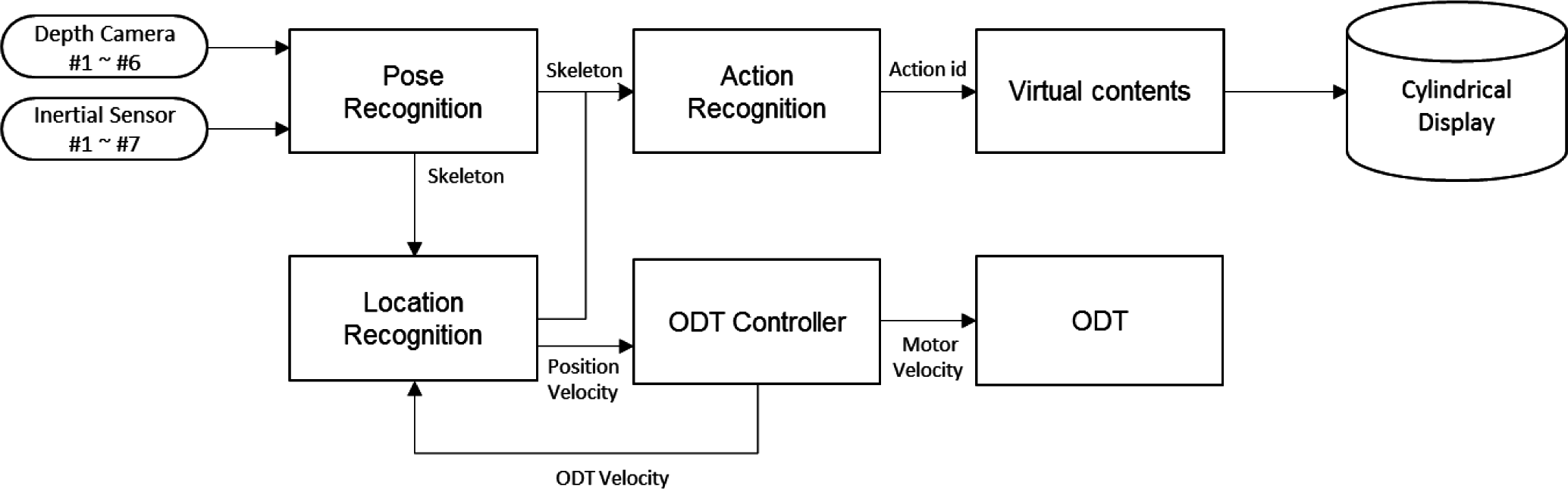
This section describes the hardware and software configuration of the proposed “Omni Directional Movement based Interactive (ODM-I) system”. The ODM-I system is proposed to develop a highly immersive soldier training system consisting of major software modules: pose recognition, location recognition, action recognition, ODT controller and virtual contents and two hardware parts such as cylindrical displays and an ODT type of locomotion interface. The information flow and the order of processing are shown as Figure 1.
Pose recognition is a software module which tracks the human pose in real time by using motion capture technology. We selected two kinds of sensors. One is a depth sensor and the other is an inertial sensor. Pose recognition extracts the trainee’s joint position in 3D space by using real time data collected from depth sensor or motion sensors. The skeleton data are then passed to the location recognition software module to analyze the trainee’s position and velocity, and to the action recognition software module to classify the trainee’s current action. Action classification is performed by using the machine learning algorithm such as “Random Forest”, “Support Vector Machine” and “K-NN”, etc., according to the sort of collected features. Identified actions such as “walk forward”, “run”, “crouch-walking”, “weapon change”, etc., serve as an input signal to the virtual contents, and it means that the majority of the keyboard commands can be replaced by a trainee’s movement itself, like in the real world. In addition, recent work has shown that translating the recognized gesture into voice [10] can be another use case in battlefield application.
Location recognition is a software module that estimates trainee’s position and velocity for the ODT controller and virtual contents module. The estimated position and velocity are important input data for controlling the ODT in a reactive way with high precision. The ODT controller generates the value of motor velocity through a high and low level motor control algorithm. The main theme of this paper is related to location recognition and the ODT controller and the detailed approach will be described in Section 3.
In our system, there are two types of virtual contents: one is our own development simulating the outdoor shooting training and the other is COTS First Person Shooting (FPS) game. In the virtual contents, a trainee’s movements are represented by an animated avatar, which interacts with the depicted enemy in the contents.
In the virtual simulator, human pose and location recognition is a key component which interconnects the trainee’s movement with virtual content and/or locomotion interfaces. Related work shows that there were a number of trials to develop the virtual training simulator using locomotion interfaces. Due to the intrinsic features of the locomotion interfaces, it is not easy to implement natural walking over the platform. To overcome the problem, the ODM-I system aims to develop highly advanced control software for smoother controlling of the locomotion platform by utilizing the trainee’s motion capture.
3. Control of the ODM Locomotion Interface
We mentioned in the introduction the reason why locomotion interface is important in the virtual simulator. It is noted that the control method of a locomotion interface is wholly dependent on the mechanical structure. In general, there are two approaches in treadmill control: feedback and feedforward control. In feedback control, the trainee’s position is steered back to a reference point whenever it diverges from the point. In the Cyberwalk project [11], x and y directions of locomotion interface are actuated independently and are controlled by a human’s head position tracked by an infra-red reflecting marker attached on a helmet. The developed Cyberwalk locomotion interface and control system enabled the user to feel like they were walking on the ground due to its mechanical features and smoother control system.
If we use the velocity data as a control parameter, then the reaction to the control command can be applied directly to the treadmill speed controller as a concept of feedforward control. Yoon [12] proposed a treadmill control algorithm which estimates swing foot velocity to enable user-driven treadmill training in gait rehabilitation. In this case, the treadmill has a split-belt and operates in one-direction.
The most important thing in the locomotion control is to make a trainee feel like they are really walking over ground. In our study, we selected a roller-based circular type treadmill as the locomotion interface because it has several advantages for interacting with military training contents. The trainee can walk in a forward direction and move in a lateral direction, too, while the treadmill is moving in the reverse direction of the trainee, toward the center (or reference) point. The principle of the control algorithm is: the control algorithm is required to keep the position of the trainee at the center (or reference position) of the treadmill; speed of the treadmill should be changed adaptively by the trainee’s velocity to prevent the instability caused by an abrupt stop or initial step forward.
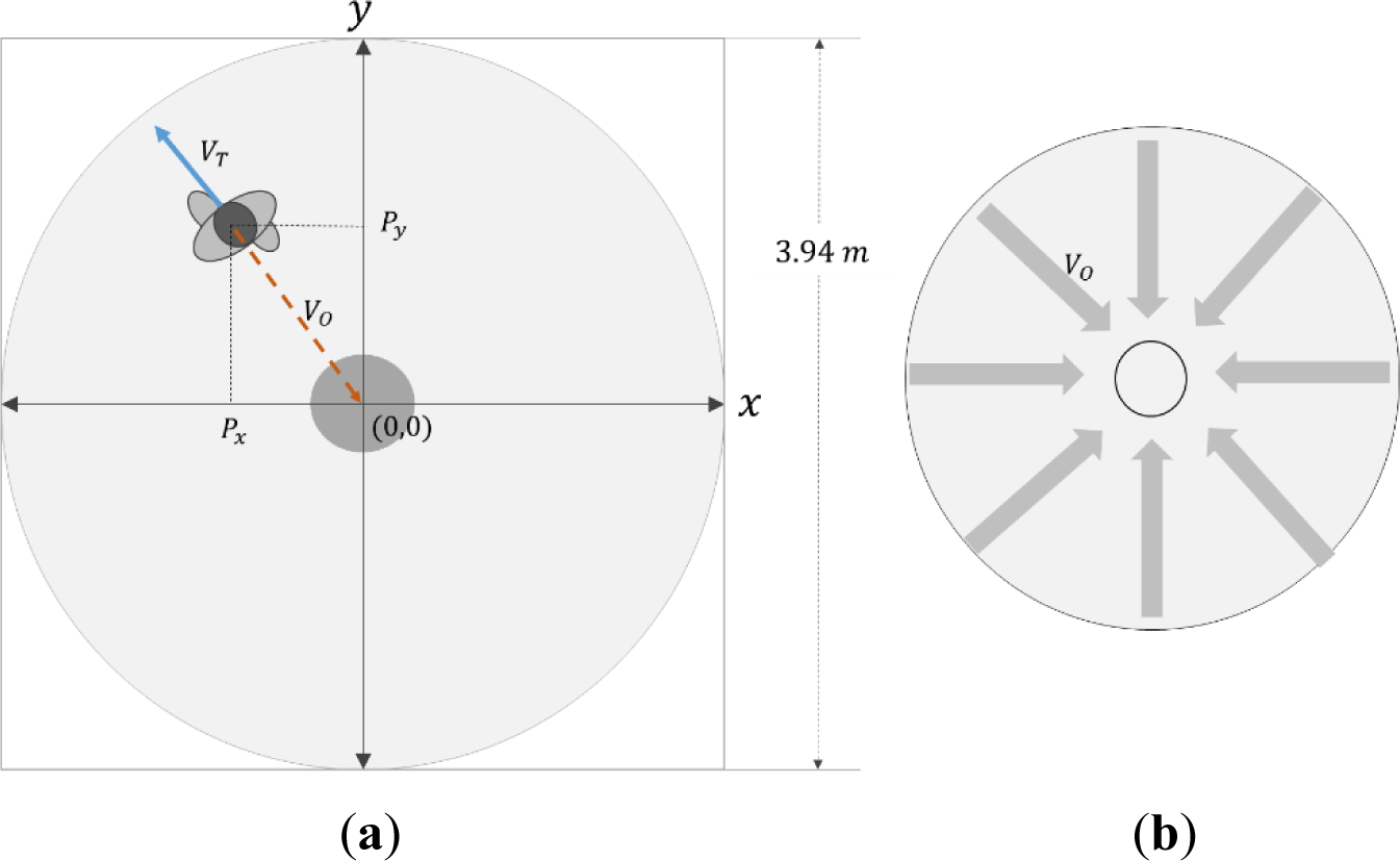
When controlling the locomotion interface, the most feasible control parameters are the trainee’s position and velocity. As shown in Figure 2, if we utilize the circular type of one-dimensional treadmill, we can set the reference position of the trainee at the treadmill center. The trainee’s position, which is tracked by sensors, is defined as:
On the other hand, the concept of the trainee’s velocity is affected by two factors: world velocity and treadmill velocity. World velocity is defined as the rate of displacement change per time unit of a trainee. Treadmill velocity is defined as the locomotion interface velocity which is generated by the ODT Controller. Then, the trainee’s velocity is decomposed by Equation (2):
Based on the concept of Equation (2), we can decompose the vector of ODT velocity into x-axis and y-axis vectors:
The velocity of a trainee can be calculated by the difference of displacements between two consecutive measurement times:
The obtained values are transmitted to the ODT Controller to move the locomotion interface forward and backward according to the trainee’s movement. If we set the reference position at the middle point of the ODT, then the direction of the generated motion can vary depending on the trainee’s walking speed. If trainee’s walking speed is slower than the ODT velocity, the motion direction is reversed. Additionally, the values obtained in Equations (5) and (6) are transmitted to the virtual content to synchronize the moving event with the trainee’s real heading, velocity, etc. A major challenge is to develop an algorithm for moving the trainee to the center of the ODT with the following prerequisites: minimizing human perception error and maintaining the trainee’s stability.
4. Estimation of Control Parameters
Though there have been a plenty of approaches to capture human motion more accurately and in a timely manner, frequently used sensors are narrowed down to two to three sensors. It can be seen that recent studies have focused on sensors such as optical, inertial and depth sensors. In this paper, the function of pose and location recognition is developed by using the Microsoft Kinect™ 1.0 and Xsens MTx inertial sensors.
4.1. Depth Sensor Based Location Recognition
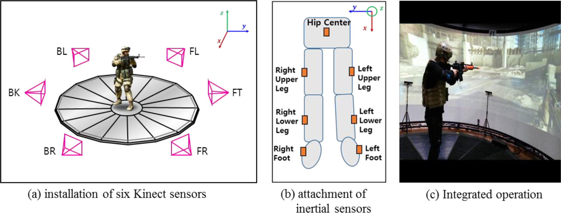
It is known that the Kinect sensor has an optimal detection range of between 1.2 to 3.5 m. In our environment the detection range falls into between 1.2 to 2.0 m and the detection range of Kinect is not enough to cover the whole locomotion platform of which the radius is 1.97 m. To resolve the problem, we simulated the optimal number of Kinects for the spatial arrangement, as a result, it is concluded that at least six Kinects are needed to cover our target environment. Kinect generates three dimensional coordinates for twenty joints in a form of human skeleton. Wang [5] estimated the reliable skeleton from the two Kinects by using the constraints of bone-lengths and weight factors. We do not describe the method of how to extract a single skeleton from multiple Kinects here since it is out of scope for this topic.
In Kinect, twenty joint positions are tracked in the user’s skeleton. Among them, we focus on the position of lower body parts which are the joint position of “Hip Center (HC)”, “Hip Right (HR)”, “Knee Right (KR)”, “Ankle Right (AR)”, “Foot Right (FR)”, “Hip Left (HL)”, “Ankle Left (AL)” and “Foot Left (FL)”.
In general, the HC joint position is considered the most influencing parameter to control the ODM-I locomotion interface, because the hip center is near the human’s center of mass. On the other hand, Feasel [13] suggested the use of the position of the feet captured by using ground reaction force for the trainee’s location. Thus we selected three joints as our parameters of interest, e.g., HC, FR, and FL. Two-dimensional coordinates of each joint position are the basic data set for depth sensor based location recognition. Kinect provides only the position values, but the velocity value can be calculated as Equation (8) by using the difference of two vector coordinates.
It is noted that the calculated result using the formula in Equation (8) might have latent errors because the estimated moving position is relatively huge compared to the time interval of two consecutive frames, . In such case, it is recommended to use a filter to smooth out of bound values.
4.2. Inertial Sensor Based Location Recognition
We extend the control algorithm by using the inertial sensor to complement the shortcomings of the depth sensor. Kinect sensors generate the skeleton data with low and varying sampling frequency (25~35 fps), which may result in the failure of key event detection, especially when movements are fast.
The inertial sensors applied in this paper include three orthogonal accelerometers and three orthogonal rate-gyroscopes, measuring linear acceleration and angular velocity respectively. These signals are transmitted to the software module “location recognition” with a predetermined sampling rate (120 Hz). By processing signals from the sensor it is possible to track the position and orientation of a device.
In our system, seven inertial sensors are used to track the trainee’s lower body pose and location (refer to Figure 3b). Estimating the “parameters of interest” in inertial sensors needs several steps of numerical formulation. After a short process of calibration, as a first step, it is necessary to estimate the orientation of each sensor. Inertial sensors are attached to the waist, the right and left thigh, the right and left lower leg, and the right and left foot. Sensor orientation of the upper and lower leg is estimated by applying the Attitude Reference System (ARS) based on the Kalman Filter.
To track the foot position and velocity, the Zero Velocity Update (ZUPT) algorithm is applied for both feet. In order to accurately estimate the walking direction, the magnetometer signal is used for the waist. Combining all the estimated values from each sensor and kinematic information measured on the trainee’s body, final estimates for the parameters of interest (position, velocity and attitude) are derived. During the analysis, the Extended Kalman Filter (EKF) is used as a basic optimization tool. If we define the error states as Equation (9), drift error is corrected by EKF operating on the error states ,
Here, is a direction cosine matrix of the body to navigation frame, is an identify matrix, is a sampling time and is an acceleration signal in a navigation frame. Once the position and velocity of the foot is estimated, then the value becomes the measurement value to EKF for waist position and velocity calculation.
Since the trainee is walking on the ODT, external ODT velocity should be applied to the obtained joint velocity. The ZUPT needs to be modified because the speed of the trainee is not zero while the foot of the trainee is in contact with the ODT, in other words, in stance phase. The speed of the foot is the same as the driving speed of the ODT, so the measurement model equation can be defined as Equations (11) and (12), where z is velocity measurement in stance phase.
5. Experimental Results
5.1. Design of Experiment
To evaluate the proposed control algorithm, data was captured using seven MTx inertial sensors from Xsens, recording the data at 120 fps. Figure 3 shows the experimental setup and attached sensor locations to a human body. Six Kinect sensors are also employed to track the trainee’s full skeleton. In order to get a ground truth reference for the experiment, the Optitrack® motion capture system was installed in our system. Eight optic cameras are installed on the upper frame of the cylindrical display and four cameras are installed on the bottom frame. The Optritrack captured the data at 120 fps to match the Xsens MTx sampling period.
In view of ODT operation, the adaptive control function was already developed and we set up the ODT’s velocity as 1 km/h, 2 km/h, 3 km/h and 4 km/h to validate the proposed approach. The subject was asked to perform a series of identical walking patterns for each speed condition. Even though we captured and tracked the lower body of a trainee, only the HC, FL and FR are reported for analysis purpose. It is noted that the experimental scenarios for depth sensor-based capture are different from those of inertial sensor-based capture to exemplify the sensor specific features. We used low pass filtering on the inertial sensors’ gyro signal. The cut off value is determined as 5 Hz with multiple experiments and consideration of the operational environment. The value can be compared with the recent study on smartphone-based gait recognition [15]. In the study, they suggested the sampling rate of 32–36 Hz with noise filtering at level 2.
5.2. Depth Sensor Results
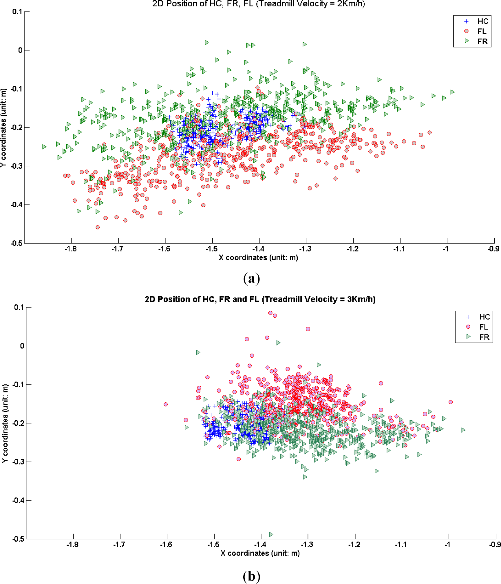
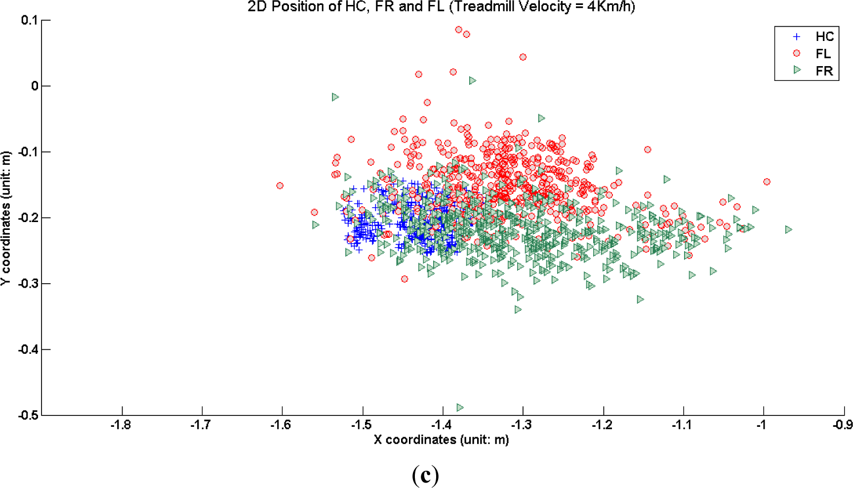
This section summarizes the experimental result of depth sensors. To identify the covered area of each joint on the ODT plane, we analyzed the scatter plot for each ODT velocity. Figure 4 shows how much the joint positions are spread within the ODT. FL and FR span a wider area in the case of 2 km/h ODT velocity compared to 3 km/h and 4 km/h cases. It can be explained by the fact that when the velocity of ODT 2 km/h is too slow to keep up with normal adult subject’s walking speed, the tendency of the footstep to go further than the reference position occurs. Note that HC positions are located in the frontal side of the coordinates cloud in the case of 3 km/h and 4 km/h. This implies that trainee’s upper body was slightly inclined forward so as not to lose balance from the external forces driven by the moving treadmill. Dispersion in the Y-axis direction decreased with the increase of the ODT speed.
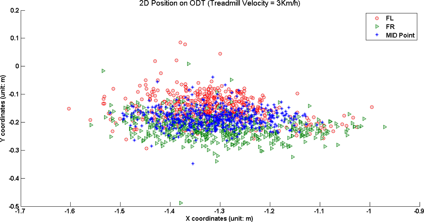
If we use the HC as the control parameter for the position-based feedback control for the ODT then the resulted value of ODT velocity will be higher than the value obtained from the FL or FR. From this, it can be seen that choosing the control point of human body is very important for stable control of the ODT. The midpoint of the left and right foot positions is proposed as the main parameter of position-based feedback control for the ODT. Figure 5 shows that the midpoints are located in a balanced way representing two key factors: neutral position of left and right foot and more information on the moving direction.
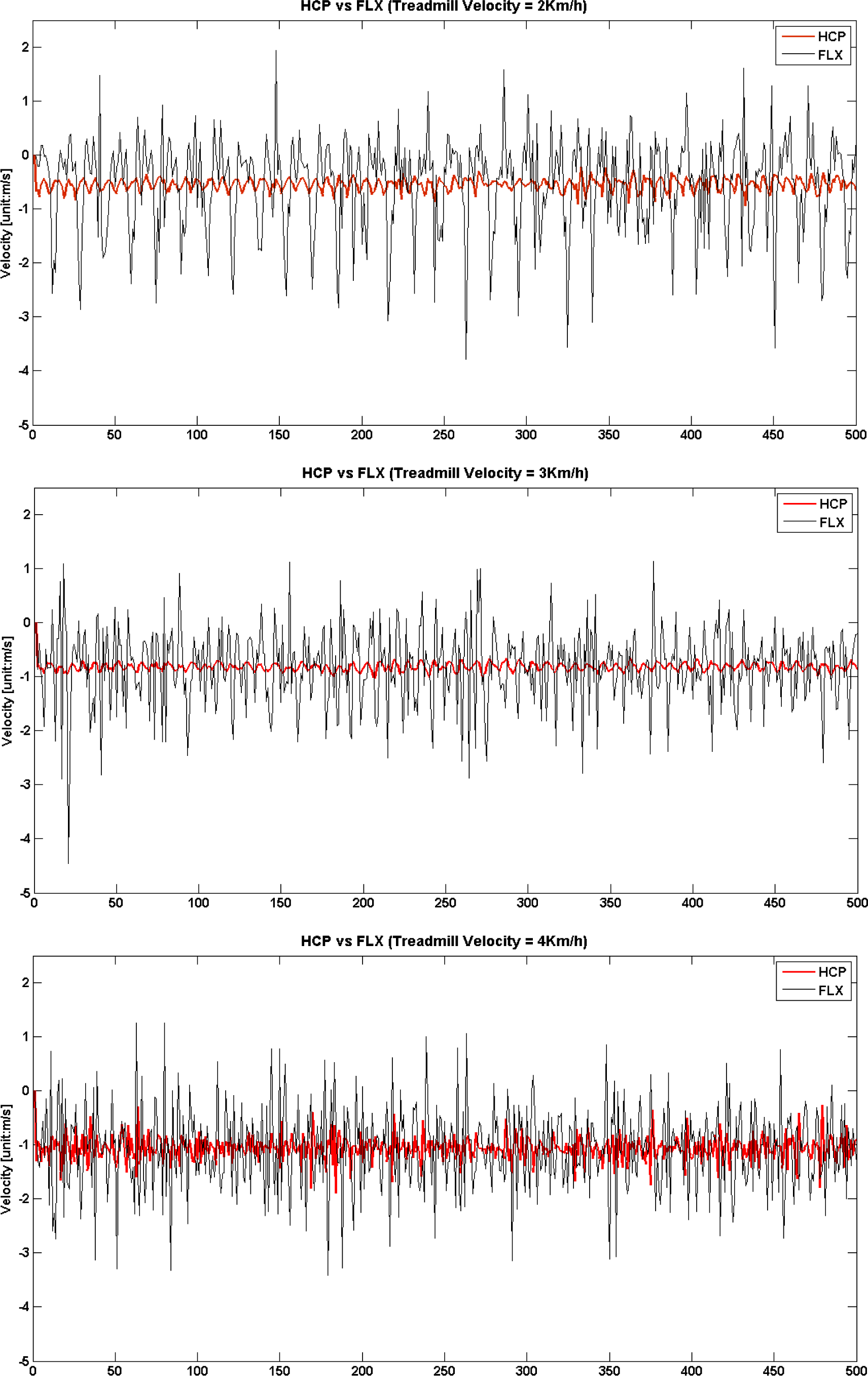
Velocity estimation results are derived using the formula defined in Equations (5) and (6), and shown in Figure 6. Only the X-axis direction velocity is compared among HC and FL for simplicity. In the figure, the solid red line represents the estimated velocity of HC and it looks stable during the experiment. On the other hand, the dotted black line represents the estimated velocity of FL, and it has noisy fluctuations at a glance. There are basic statistics given in Table 1, and it can be seen that average values are quite well adjusted to external ODT velocity in both joints, but standard deviations of FL are much higher than the values of HC, because the dynamics of both feet are much higher than the HC.
In view of velocity parameters, two approaches can be taken for ODT control. First, feedforward control is applicable if we can predict the speed of the kinematic joint as early as possible. Second, the trainee’s intention to start or stop walking can be identified and controlled by detecting the ratio of the double stance over gait duration. Yoon [12] verified that if the double stance phase is 20% longer than the previous step, it is considered that the trainee intends to stop. The data enables smoothed finalization of walking for the trainee and therefore it is important control information.
But, when we use the Kinect, we get the velocity data indirectly from the difference between the trainee’s displacements in time, and it means that estimating the velocity in advance isn’t possible. In that sense, an additional way is needed to provide a resolution to the deficiency.
5.3. Inertial Sensor Results
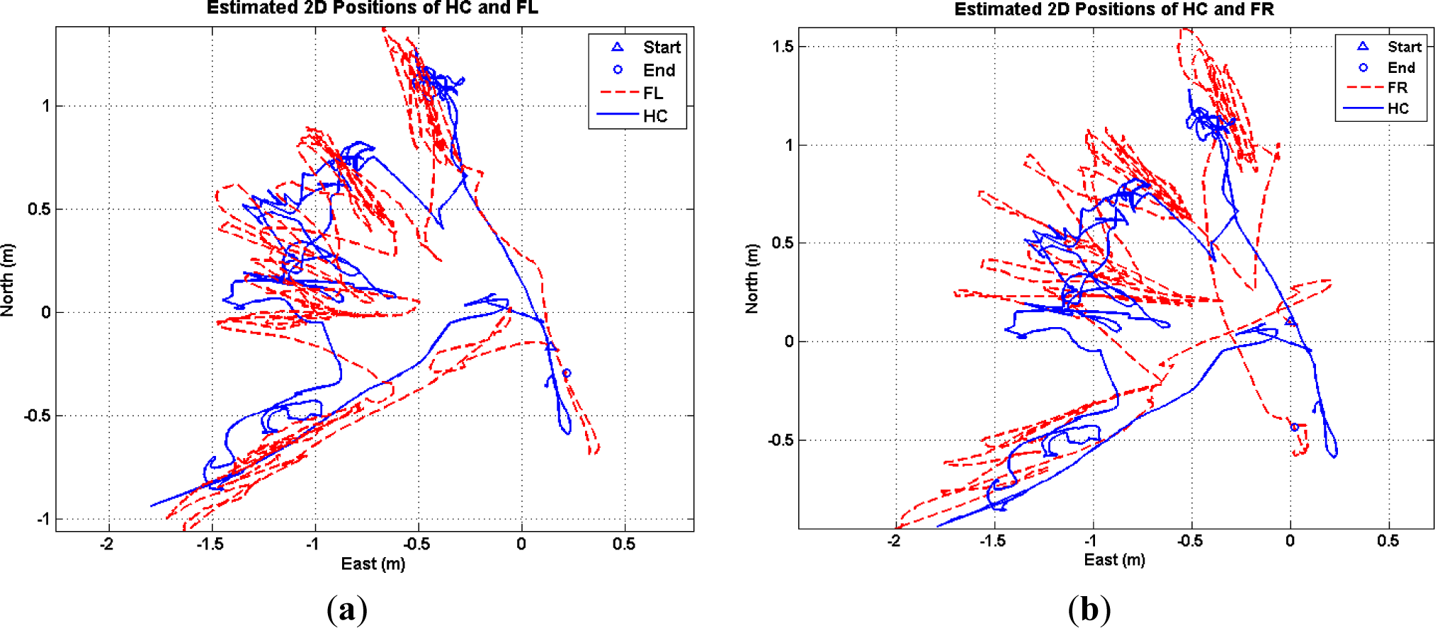
This subsection summarizes the experimental results of inertial sensors. The trainee wore seven inertial sensors on the lower body part and walked on the ODT with a pre-defined scenario: start walking from the center point and keep walking on one quarter of the ODT, including a step forward in a lateral direction five times and returning to the center point again. The estimated positions are shown in Figure 7. The left graph is the estimated position of HC and FL joints and trajectory of both joints show a similar pattern but the FL position reaches far more than the position of HC. The right graph shows the same results for the FR case. As proposed in Section 5.2, midpoint of both feet will be the best control point on the human skeleton to serve as an accurate and reactive input parameter for ODT control.
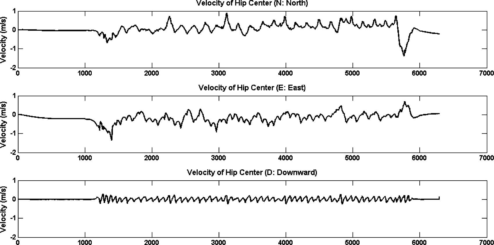
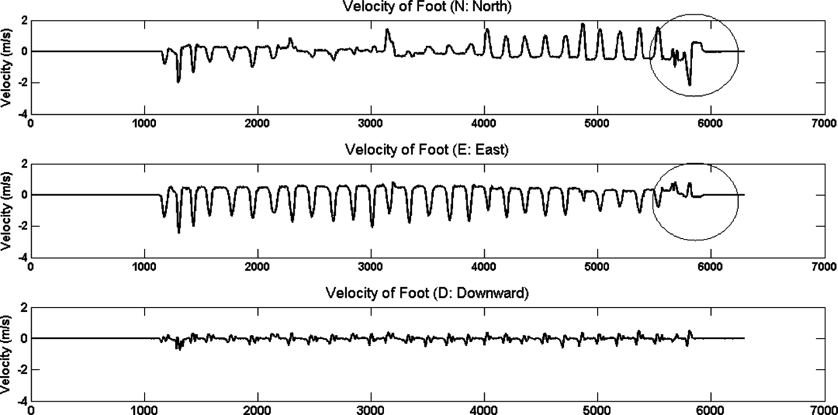
The velocity estimation is done with inertial sensors with a sampling rate of 120 Hz and is shown in Figures 8 and 9. There are three graphs in each figure, first is the velocity in the northern direction (negative x direction in our system), second is in the eastern direction (negative y direction in our system) and third is in downward direction (negative z direction in our system). In Figure 8, the velocity of HC shows relatively smooth patterns except in the eastern direction, which is a similar result as the depth sensor case (refer Figure 6). In the Foot velocity case, there is a distinct pattern which shows the repeated reversed sinusoidal curves, which are interconnected with an almost flat line in the second graph. This pattern is the typical gait cycle, where the narrow sinusoidal part is the swing phase of foot and the flat line part is the stance phase. In usual ground conditions, the stance phase can be detected by analyzing three-axis accelerometer signals using the ZUPT, detecting the positive peak closely followed by a negative peak [16]. One important assumption here is that while the foot is in stance phase, the velocity of the foot is updated as the same value of ODT’s velocity. This assumption was applied to correct the errors, hence, to update the state variables.
In the case of inertial sensors, the foot joint signal gives richer information than HC. In Figure 9, we can find the point (around 5000 in x-axis) that the velocity in the eastern direction is diminished slowly, and at the same point the velocity in the north direction is amplified. It is because the trainee intended to stop walking and returned to the center point. From this, we can detect the directional change of a trainee earlier in the walking phase, and the information can then be used for faster, more reactive ODT control.
5.4. Accuracy Evaluation
This subsection describes the accuracy evaluation results of two approaches. As mentioned in Section 5.1, we used the Optitrack® motion capture system as our ground truth test environment. Since the commonly obtained information format from each sensor is lower body joint positions, the 3D coordinate values of the skeleton estimated from the Kinect and inertial sensors, are compared with the joint position values obtained from the Optitrack system. Data were synchronized between the Kinect and Optitrack, and also between the inertial sensor and Optitrack during post processing using a timestamp comparison. In Table 2, Root Mean Square Error (RMSE) values are presented for the chosen kinematic joints against the Optitrack system. The result shows that the RMSE of the depth sensor is smaller than the RMSE of the inertial sensors for all seven joints. Given that the previous studies have shown the assessment result of the single Kinect setup with static experiment scenario [17,18], our result, derived under multiple Kinect setup and treadmill-walking scenarios, shows concurrent validity with the Optitrack method.
In inertial sensors, the overall RMSE values are relatively large compared to the depth sensors, particularly, the values of the FL and FR are slightly higher than the other joints. The reason for this is vibration generated from the operation of the ODT. Inertial sensors are susceptible to external disturbances, such as vibration, steel, temperature and magnetism, so the sensor signals, especially in both feet, were affected by vibration caused from velocity of the ODT.
The RMSE values of both sensors suggest that to use the Kinect as a primary and inertial sensors as a secondary motion capture tool in our system.
6. Conclusions
This research aims to develop an effective virtual training simulator for dismounted soldiers fulfilling two purposes. The first purpose is supporting dynamic mobility for the trainee like live training and the second purpose is providing pre-exploration for the target area before entering into a real military operation. In this paper, we presented the way of estimating the control parameters for the ODT hardware and virtual content interacting with the trainee’s pose and location information. We suggested two approaches of obtaining the control parameters. First, depth sensors were used to estimate the kinematic skeleton information of a trainee, and among the full body joints, HC, FR and FL were analyzed. Second, inertial sensors were used to estimate the kinematic skeleton focusing on the lower body of a trainee, especially on HC, FR and FL.
The analyzed result shows that the position of HC gives almost stationary movement, so it couldn’t express the dynamic change of trainee’s movement. On the contrary, the positions of FR and FL represent the trainee’s locomotion well, but the signal amplitude is too high to be used as a control value of the ODT. Thus, it is proposed to use the midpoint of FR and FL to determine the position of a trainee, and the value can be a good candidate as a control parameter of the ODT when we apply position-based feedback control. The velocity information gives an important clue which identifies the trainee’s intention of movement. Detecting the ratio of double stance phase and the directional change of a raw signal enables us to implement feedforward control of the ODT. In this regard, inertial sensors give a better performance and dynamic but the position accuracy is lower than depth sensors.
For future development, the inertial and depth sensor-based fusion control parameter estimation will be used to take advantages of each sensor. Recent study proposed a simple sensor fusion approach, which simply combines the skeleton from the Kinect and joint angles estimated from multiple inertial sensors [19]. In this case, the kinematic control parameters are derived from the sampling rate of the Kinect, around 30 Hz. The aim of our work is to estimate the control parameters as early as possible, so we need to formulate the fusion algorithm using the skeleton estimated from the inertial sensors as a base framework. The joint positions from the Kinect will be used in assisting input values to correct the errors accumulated in the inertial sensors.
Since the proposed control parameters have strong correlation with the ODT actuation, it is needed to suggest the improved performance result by applying the proposed method. The long-term goal is to integrate pose and location analysis with all the other sub components to develop a low-cost, portable, and reactive system for highly immersive virtual simulator applications.
Acknowledgments
This work was supported by the ICT R&D program of MSIP/IITP. (R0101-15-0168, Development of ODM-interactive Software Technology supporting Live-Virtual Soldier Exercises).
Author Contributions
Soyeon Lee wrote this manuscript; Sangjoon Park, Kyoil Chung and Choongho Cho contributed to the writing, direction and content and also revised the manuscript.
Conflicts of Interest
The authors declare no conflict of interest.
References
- Jaclyn, H.; Jason, W.; Brian, W. Embedded LVC Training: A Distributed Training Architecture for Live Platforms. Proceedings of the Interservice/Industry Training, Simulation, and Education Conference (I/ITSEC), Orlando, FL, USA, 3–6 December 2012; pp. 1–10.
- Pablo, F.; Carlos, F.R.; Jose, T.H.; Juan, C.B.; Raul, O.; Luis, B. A Shooting Simulator from Boats. Proceedings of the 9th International Conference on Computer Graphics Theory and Applications, GRAPP’14, Lisbon, Portugal, 5–8 January 2014; pp. 88–95.
- Emilie, A.R.; Robert, R. Optimum Dismounted Soldier Training Experience: Live or Virtual? Proceedings of the Interservice/Industry Training, Simulation and Education Conference (I/ITSEC), Orlando, FL, USA, 2–5 December 2013; pp. 1–11.
- Scott, M.J.; John, C.; Pat, G. Advanced Animation Techniques in a Dismounted Soldier System. Proceedings of the Interservice/Industry Training, Simulation and Education Conference (I/ITSEC), Orlando, FL, USA, 1–5 December 2014; pp. 1–10.
- Wang, Z.C.; Tsai, C.C.; Chien, M.C. Design of an Intelligent Soldier Combat Training System. Int. J. Autom. Smart Technol. 2012, 2, 309–317. [Google Scholar]
- Frank, S.; Yon, V.; Jennifer, C.; Anatole, L. Human Walking in Virtual Environments; Springer: New York, NY, USA, 2013. [Google Scholar]
- Patricia, M.M.; Jonathan, B.D.; Jason, M.W. Walking variability during continuous pseudorandom oscillations of the support surface and visual field. J. Biomech. 2010, 43, 1470–1475. [Google Scholar]
- Harrison, P.C.; Jim, A.F.; Phuong, K.T.; Patrick, W.W. Improvements in the Omni-Directional Treadmill: Summary Report and Recommendations for Future Development; ARL-TR-3958, Report of Army Research Laboratory; Army Research Laboratory (ARL): Aberdeen Proving Ground, MD, USA, 2006; pp. 1–63. [Google Scholar]
- Lee, L.; James, B.; Russell, L.W.; Eli, P. A Feedback-Controlled Interface for Treadmill Locomotion in Virtual Environments. ACM Trans. Appl. Percept. 2007, 4, 1–22. [Google Scholar]
- Lee, J.K.; Kang, W.M.; Park, J.H.; Kim, J.S. GWD: Gesture-Based Wearable Device for Secure and Effective Information Exchange on Battlefield Environment. J. Converge. 2014, 5, 6–10. [Google Scholar]
- Souman, J.L.; Giordano, P.R.; Schwaiger, M.; Frissen, I.; Thummel, T.; Ulbrich, H.; Luca, A.D.; Bulthoff, H.H.; Ernst, M.O. CyberWalk: Enabling Unconstrained Omnidirectional Walking through Virtual Environments. ACM Trans. Appl. Percept. 2011, 8, 25–46. [Google Scholar]
- Yoon, J.; Park, H.S.; Damiano, D.L. A novel walking speed estimation scheme and its application to treadmill control for gait rehabilitation. J. Neuroeng. Rehabil. 2012, 9, 1–13. [Google Scholar]
- Feasel, J.; Kassler, L.; Brooks, F.P.; Lewek, M.D. The integrated virtual environment rehabilitation treadmill system. IEEE Trans. Neural Syst. Rehabil. Eng. 2011, 19, 290–297. [Google Scholar]
- Minsu, L.; Changook, P.; Hojin, J.; Jinwoo, S. Use of Multiple Wearable Inertial Sensors in Human Localization. Proceedings of the ION Pacific PNT Conference, Honolulu, HI, USA, 20–23 April 2015.
- Thang, H.; Thuc, N.; Chuyen, L.; Son, D.; Deokjai, C. Adaptive Cross-Device Gait Recognition Using a Mobile Accelerometer. J. Inf. Process. Syst. 2013, 9, 333–348. [Google Scholar]
- Ahn, J.; Han, R. An indoor augmented-reality evacuation system for the Smartphone using personalized Pedometry. Hum.-Centric Comput. Inf. Sci. 2012, 2, 1–23. [Google Scholar]
- Ross, A.C.; Yong-Hao, P.; Karine, F.; Callan, R.; Kate, E.W.; Linda, D.; Adam, L.B. Validity of the Microsoft Kinect for assessment of postural control. Gait Posture. 2012, 36, 372–377. [Google Scholar]
- Tilak, D. Evaluation of the Kinect™ sensor for 3-D kinematic measurement in the workplace. Appl. Ergon. 2012, 43, 645–649. [Google Scholar]
- Destelle, F.; Ahmadi, A.; O’Connor, N.E.; Moran, K. Low-Cost accurate skeleton tracking based on fusion of Kinect and wearable inertial sensors. Proceedings of the 22nd European Signal Processing Conference (EUSIPCO), Lisbon, Portugal, 1–5 September 2014; pp. 371–375.


| Treadmill Velocity | 2 km/h (≈0.55 m/s) | 3 km/h (≈0.83 m/s) | 4 km/h (≈1.11 m/s) | |||
|---|---|---|---|---|---|---|
| Kinematic Joints | HC | FL | HC | FL | HC | FL |
| Velocity (mean) | −0.5495 | −0.5439 | −0.8210 | −0.8225 | −1.0721 | −1.0689 |
| Standard Deviation | 0.1145 | 0.4908 | 0.0778 | 0.7154 | 0.2294 | 0.7766 |
| Kinematic Joints Position (Lower Body) | RMSE (Unit: m)
| |
|---|---|---|
| Depth Sensor | Inertial Sensor | |
| HC (Hip Center) | 0.1209 | 0.2932 |
| HL (Hip Left) | 0.1360 | 0.2589 |
| HR (Hip Right) | 0.1519 | 0.2863 |
| KL (Knee Left) | 0.1442 | 0.2615 |
| KR (Knee Right) | 0.1440 | 0.2667 |
| FL (Foot Left) | 0.1374 | 0.3458 |
| FR (Foot Right) | 0.1463 | 0.3030 |
| Average | 0.1401 | 0.2879 |
© 2015 by the authors; licensee MDPI, Basel, Switzerland This article is an open access article distributed under the terms and conditions of the Creative Commons Attribution license (http://creativecommons.org/licenses/by/4.0/).
Share and Cite
Lee, S.; Park, S.; Chung, K.; Cho, C. Kinematic Skeleton Based Control of a Virtual Simulator for Military Training. Symmetry 2015, 7, 1043-1060. https://doi.org/10.3390/sym7021043
Lee S, Park S, Chung K, Cho C. Kinematic Skeleton Based Control of a Virtual Simulator for Military Training. Symmetry. 2015; 7(2):1043-1060. https://doi.org/10.3390/sym7021043
Chicago/Turabian StyleLee, Soyeon, Sangjoon Park, Kyoil Chung, and Choongho Cho. 2015. "Kinematic Skeleton Based Control of a Virtual Simulator for Military Training" Symmetry 7, no. 2: 1043-1060. https://doi.org/10.3390/sym7021043