1. Introduction
The millimeter-wave (mmWave) spectrum is an important part of the fifth-generation (5G) technology. mmWave refers to radio frequencies between 30 and 300 GHz, which are much higher than the frequencies traditionally used for mobile communications. In contrast, fourth-generation 4G networks typically use frequencies below 6 GHz. mmWave spectrum offers several advantages for 5G networks, including high data rates crucial for many 5G applications such as fixed wireless access (FWA), virtual reality (VR), smart cities, the internet of things (IoT), and vehicle-to-everything (V2X) communication [
1,
2,
3]. Also, mmWave advantages include low latency and larger bandwidths than traditional mobile frequencies, which allows more data to be transmitted over the network. Multiple-input/multiple-output (MIMO) antennas are essential for 5G communication in the mmWave spectrum because they can help overcome the challenges posed by the high-frequency bands [
4,
5,
6]. MIMO technology employs multiple antennas at both the transmitting and receiving ends to transmit and receive data simultaneously, increasing spectral efficiency and reducing interference. In the mmWave spectrum, MIMO antennas can help improve signal quality, increase data rates, and extend the range of 5G networks. With MIMO, beamforming can be used to direct the signal toward the intended receiver and mitigate interference from other sources, improving the overall network performance. Since mmWave signals can be easily obstructed by obstacles, MIMO antennas can help overcome these obstructions and maintain a stable and strong connection between the device and the network [
7,
8]. The use of MIMO antennas in the mmWave spectrum is critical for enabling the high data rates and low latency that 5G promises, making it an essential technology for the future of mobile communication.
Various MIMO antenna designs have been suggested in the existing literature [
9,
10,
11,
12,
13,
14,
15]. In [
9], a design has been developed for a dual-band, dual-linear-polarization reflectarray aimed at future 5G cellular applications. This design incorporates a single-layer unit cell consisting of two sets of miniature fractal patches. The unit cell enables dual-polarization operation at distinct frequencies within the Ka-band (27/32 GHz). Extensive analysis confirms the independent behavior of the unit cell across the desired frequency bands and polarizations. The proposed architecture boasts small unit cell sizes, minimal losses, a thin and simple construction, and the ability to optimize phase independently for each frequency and polarization. The dual-band, dual-polarized reflectarray cell is formed by combining two sets of miniature patches printed on a single substrate layer. Each set operates at a specific resonant frequency and provides two linearly polarized elements, each rotated by 90 degrees, thereby facilitating a dual-polarization operation mode. In [
10], a comparison was made between four different types of random arrays by calculating their array factor’s mean and variance. This enabled a partial statistical characterization of these arrays and established a link between the elemental count and aperture of the array with specific key characteristics. Since there was no straightforward analytical tool that could accurately measure the side-lobe level, the experimental aspect was given additional importance. For the purpose of achieving results and in order to experimentally analyze the side-lobe distribution, Monte Carlo simulations were performed, considering the number of radiators and the average distance between them as variables. The results obtained from these simulations demonstrated that random arrays, which allowed for restrictions on the minimum distance between adjacent components, achieved comparable performance to other methods without such limitations. Random arrays were preferred due to their ability to mitigate the effects of reciprocal coupling by ensuring that neighboring radiators were not positioned closer than a predetermined minimum distance.
In [
11], a four-port MIMO system is presented for central frequency of 30 GHz. The antenna showed 5 GHz bandwidth and the isolation is improved by incorporating a two-layer transmission-type frequency selective surface (FSS) superstrate based on planar crossed-dipole metal. After the insertion of FSS, the isolation up to 6 dB and gain up to 5 dB is improved. In [
12], a novel MIMO antenna system is presented that draws inspiration from the natural world. The central frequency of the proposed antenna system is 28 GHz, which is suitable for future millimeter-wave technologies. The antenna system contains four resonators arranged in a compact configuration, which enables it to achieve high gain and directivity. The authors used a fractal geometry inspired by the Mandelbrot set to design the individual antenna elements. This geometry provides multiband operation and enhances the bandwidth of the antenna system. The proposed MIMO antenna system also has high isolation of 25 dB between the elements.
In [
13], a mmwave antenna system with 4G antennas are presented together at chassis with dimensions of 150 × 77.8 mm
. The isolation among mmwave elements is noted to be nearly 20 dB and ECC < 0.0125. To enhance the separation between the 5G and 4G signal sources, a low-pass filter (LPF) is included. This LPF is created using a stepped impedance approach, which involves using sections of transmission lines with extremely high and very low characteristic impedance. A shared-aperture beam-scanning antenna array that operates in both Ku and Ka frequency bands is presented in [
14]. The implemented antenna design utilizes four linear antenna arrays operating in the Ku-band and four linear antenna arrays operating in the Ka-band. These arrays are constructed using substrate-integrated waveguide (SIW) technology. By using the Ku-band antenna as the side walls of the Ka-band antenna, the element spacing at both frequency bands is optimized for wide-scan operation. SIW power dividers and printed circuit board (PCB) fabrication techniques are employed to design the feeding networks for the two arrays. The design also incorporates self-filtering, orthogonal polarization and optimal array layout to ensure a high level of channel isolation between the two antennas operating at different frequency bands throughout the entire range of beam scanning. Experimental validation confirms that the achieved isolation between the antennas surpasses 28 dB at Ku-band and 70 dB at Ka-band, even under scanning angles of up to 40 degrees. This excellent isolation performance highlights the effectiveness of the proposed shared-aperture concept and the validity of the design results. One of the advantages of this design is its compact topology, but a potential limitation is the complexity of fabrication due to the use of SIW technology.
The antenna presented in [
15] is designed as a monopole antenna. It consists of a circular patch with a rectangular slot cut out from it, along with a partial ground plane. This specific antenna is intended to work within a frequency range spanning from 36.6 GHz to 39.5 GHz, with the center frequency being 38 GHz. To enhance the antenna’s performance, measures have been taken to minimize interference between different parts of the antenna setup. Four stubs have been added strategically to reduce unwanted interaction between antenna elements at the desired frequency bands. This is crucial to achieve a high level of isolation, ensuring that the signals transmitted and received by the antenna remain clear and distinct. Moreover, in order to boost the antenna’s signal strength, an FSS sheet is incorporated. This FSS is designed to function at the same frequency bands as the antenna and is positioned underneath the suggested MIMO system. This FSS acts like a reflector, directing and focusing the signals in a specific direction, thereby increasing the antenna’s gain or signal strength. However, one primary drawback is the antenna’s relatively narrow bandwidth. It can only effectively operate within a small range of frequencies from 36.6 GHz to 39.5 GHz. Another challenge arises from the integration of the frequency-selective structure at millimeter-wave frequencies. Millimeter-wave technology operates in extremely high-frequency ranges, which can make the fabrication and implementation of these structures quite complex, especially in compact devices.
Similarly, in [
16], a four-element MIMO system is presented with bandwidth ranging from 27 to 29 GHz. By employing the spatial diversity approach, the isolation of the antenna system has been significantly enhanced, achieving isolation levels of more than 24 dB across the desired frequency range. Several isolation techniques help in minimizing the coupling among radiating elements. These techniques include the use of electromagnetic bandgap structures (EBG) [
17,
18], defected ground structures (DGS) [
19,
20], and meandered line resonators [
21,
22]. In [
17], with the use of EBG and hairpin shape DGS, the isolation among radiating elements was improved up to 32 dB.
This article presents a four-element printed MIMO antenna operating over mmwave spectrum from 25 to 38 GHz. The proposed MIMO systems offer polarization diversity characteristics with self-isolation of >24 dB throughout the band of interest. The antenna is fabricated and tested using an in-house facility. The other MIMO parameters are tested and found to be in safe limits. The structure of the paper is as follows.
The literature review and detailed introduction is given in
Section 1.
Section 2 covers the working principle of antenna and MIMO configuration.
Section 3 shows the fabricated prototype and obtained results discussion, followed by a comparison table with the state-of-the-art technology and a conclusion.
2. Antenna Design
The proposed antenna is shown in
Figure 1. The plow-shaped antenna comprises of a four resonating strips with two strips turned at certain angle. These strips generate the wideband response. The proposed antenna is designed on ultra-thin 0.254 mm R05880. The ground plane consists of a tunable notch at the top mid-section of ground plane. The designed is simulated in Computer Simulation Technology (CST) 2019 with higher meshing environment of 15 cells per wavelength. The complete dimensions of the proposed antenna in millimeters (mm) is shown in
Table 1.
Figure 2 explains the design evolution process of the proposed antenna. The effective length of the resonating element with the contribution of each segment has been derived using the following equation. It is shown.
where
c is the length of the horizontal segment,
d is length of the tilted vertical segments at each end of the segment
c.
ang is the angle between
c and
d, which is 20
. The segment
d has vertical and horizontal components which have lengths defined by
and
, respectively. The currents flowing through the segments
and
would generate some opposing currents flowing on the segments
c and
b due to the mutual coupling. Therefore these opposing currents would cause some degree of cancellation in the corresponding segments. This effect manifests itself as some reduction in the length. The degree of reduction is given with the parameters
m1 and
m2 in the equation.
defines the percentage of length on each vertical segment of
d that is left after the coupling effect due to the currents of
b. Similarly
m2 defines the percentage of length on each horizontal segment of
d that will be subtracted from
c. The
L causes the resonance on the unit cell response. The frequency of this resonance is given by the following equation.
where
C is the speed of light,
is the operating frequency and
is the effective dielectric constant.
Figure 3 shows the parametric analysis of the proposed plow-shaped antenna. The two parameters analyzed are the ground notch and the angle among the plow-shaped strips. Both parameters play a significant role in shifting the antenna frequency.
Figure 3a shows the resonance response with respect to incident angle among strips while
Figure 3b shows the response with respect to ground notch. As seen from the Figure, the angle between the strips of plow-shaped antenna plays a significant role in resonance. As the angle is decreased, the resonance frequency is diminished. The desired resonance response occurs at an angle of 20
. At a 25
angle, the resonance moves to the higher frequency of 31 GHz. Similarly, the ground notch helps in matching the impedance of the antenna on the desired frequency. With a value of 1.4 mm, the ground notch exhibits resonance from 25 to almost 39 GHz but with the maximum return loss value of 18 dB. The desired response is achieved at 1.5 mm where the return loss value of 30 dB is achieved but with the trade-off on bandwidth. The bandwidth at the higher value is decreased from 39 to 38 GHz. Further increase in ground slot value shifts the frequency to a higher value and also decreases the bandwidth response.
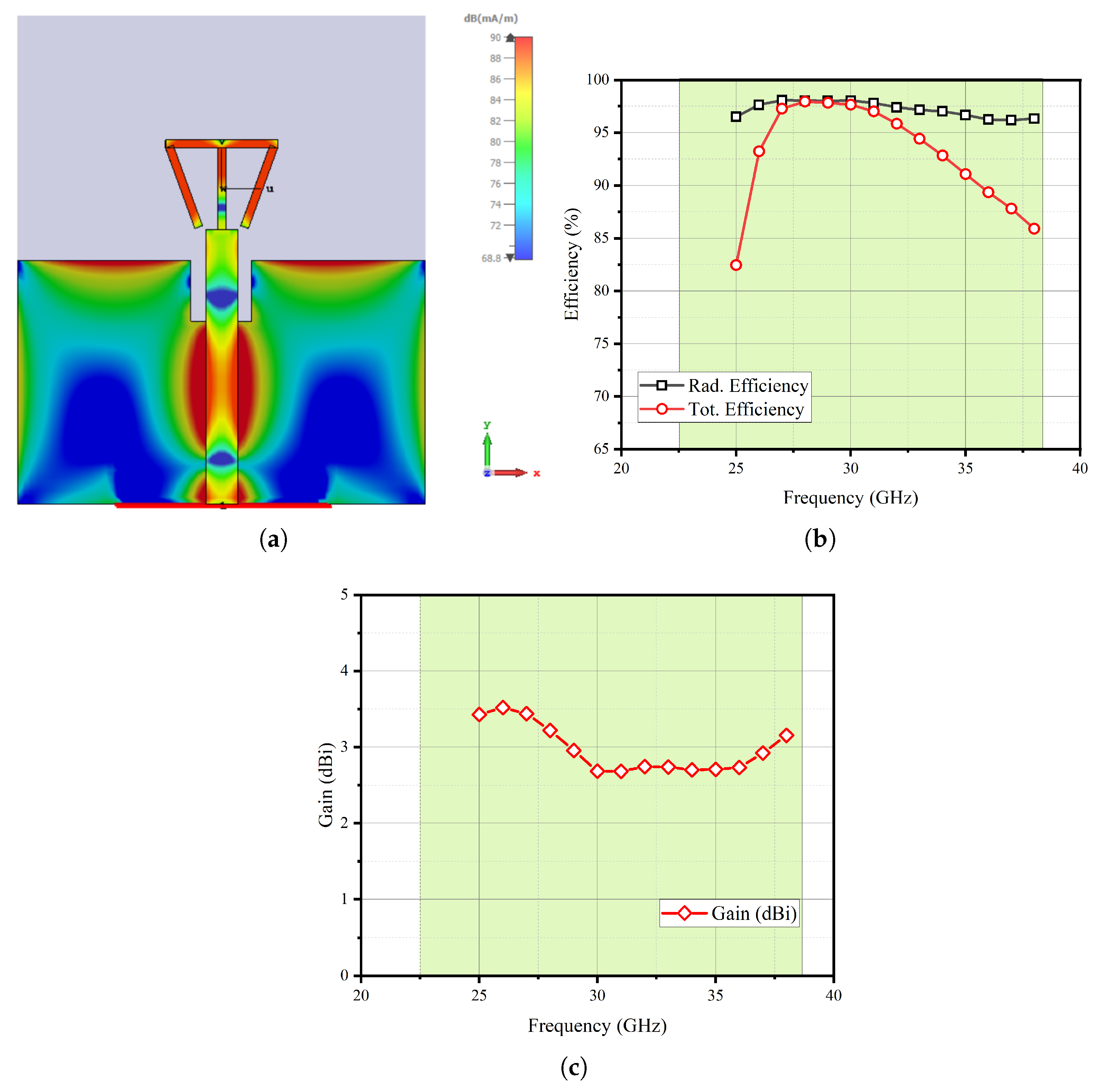
Figure 4 presents the surface current distribution and the gain with the efficiency of the antenna. The surface current presented at 28 GHz resonance shows the significance of the angled strips and notch in generating the desired wideband response. The efficiency ranges between 94 and 96% for radiation efficiency, while for total efficiency, it is between 80 and 92%. The gain at 28 GHz is noted to be 3.2 dBi.
4. MIMO Performance Parameters
MIMO performance parameters are metrics used to evaluate the effectiveness and efficiency of MIMO antenna systems in wireless communication. These parameters provide insights into the system’s capacity to improve data rates, enhance signal quality, mitigate interference, and achieve reliable transmission in multi-path environments. These parameters include the envelope correlation coefficient (ECC), mean effective gain (MEG), and diversity gain (DG). ECC is an important parameter in MIMO systems that quantifies the correlation between the signals received by different antenna elements. It reflects the degree of spatial correlation and mutual coupling between the antennas. The ECC of the proposed plow-shaped MIMO antenna system is derived using far-field characteristics as given in Equation (
1) [
23,
24]. The ECC among any two radiating elements is found to be less than 0.2, as shown in
Figure 10a,b. Similarly, relying solely on stand-alone antenna gain as a measure of performance can be unreliable, as antennas are commonly used in real-world settings rather than in anechoic chambers. The criteria for the proposed system are as follows. Antennas operate in specific situations and for specific applications, and it is crucial to consider the impact of the surrounding environment on their radiation properties in order to accurately assess their performance. The mean effective gain (MEG) offers valuable insights into the anticipated performance of the antenna in a multi-path environment, providing an understanding of its ability to handle signal reflections and interference caused by multipath propagation by considering the complex interactions and reflections that occur in real-world scenarios. The MEG of the investigated MIMO system is shown in
Table 2. The MEG is calculated using Equation (
2) mentioned in [
25,
26]. Diversity gain is the measure of signal quality improvement obtained by utilizing multiple antennas in a MIMO system. In MIMO systems, the normal range for diversity gain typically falls between 9.95 to 10 dB.
Figure 8c shows the DG of the MIMO system. The evaluation of performance parameters revealed that all results were within acceptable limits, confirming that the antenna system satisfies the desired performance requirements.
where
denotes the 3D radiation pattern upon excitation of the
i antenna and
denotes the 3D radiation pattern upon excitation of the
jth antenna.
is the solid angle.
where
and
are angle of arrival and
r is the cross-polar ratio, which can be expressed as Equation (
6).
The power received by the vertically polarized and horizontally polarized antenna is represented as
and
, respectively.
In MIMO antenna systems, TARC is a crucial parameter that measures the efficiency of the antenna system in transmitting and receiving signals with minimal reflection losses [
25,
26]. A low TARC value indicates that the MIMO system can effectively transfer signals without significant losses due to reflection. This leads to improved signal quality, higher data rates, and increased overall system capacity, which are essential for achieving reliable and high-performance wireless communication. For calculating the TARC, the laboratory-measured S-parameters of a two-element MIMO antenna were used. From
Figure 10d, the TARC can be seen below 10 dB for the whole band of interest.
Channel capacity loss in MIMO antenna systems refers to the reduction in the maximum data rate due to practical constraints of the wireless channel. Multiple factors contribute to this phenomenon, including spatial correlation between antennas, fading, interference from other networks, and the presence of noise [
27,
28]. In an ideal scenario, the desired value for channel capacity loss in MIMO antenna systems would be zero, indicating no loss or degradation in the maximum achievable data rate [
29]. However, achieving zero channel capacity loss is practically unattainable due to the inherent limitations and constraints of the wireless environment [
30]. From
Figure 10e, channel capacity loss is observed below 0.5 bits/s/Hz in the operating frequency bands, which satisfies its acceptable limit condition.
Table 3 presents a comparison between the proposed work and the existing literature, shedding light on the advantages offered by the novel antenna design. Among the standout features, the most striking is its compact size, a testament to the ingenuity and innovation behind this research. By achieving a smaller form factor, the proposed antenna opens up exciting possibilities for integration into various compact devices and space-constrained applications without compromising on performance. Equally impressive is the wide bandwidth response showcased by the proposed antenna, surpassing what has been previously reported in the published literature. This expanded bandwidth translates into faster data transmission, reduced latency, and enhanced overall communication efficiency, a crucial factor in today’s fast-paced digital landscape. As data-hungry applications and emerging technologies continue to thrive, the ability of the proposed antenna to accommodate such demanding data rates is nothing short of a game-changer. Moreover, the exceptional isolation and ECC (envelope correlation coefficient) levels exhibited by the antenna further underscore its excellence in design and engineering. Isolation is a pivotal aspect in multiple-antenna systems as it determines the ability to minimize interference and cross-talk between antennas. With superior isolation, the proposed antenna ensures cleaner signal reception, reduced signal degradation, and heightened system reliability, all of which contribute to an unparalleled user experience. The high ECC levels are equally noteworthy as they signify the antenna’s ability to maintain consistent performance across its multiple input channels. This translates to improved stability, reduced signal distortion, and enhanced signal diversity, which is especially critical in achieving seamless connectivity and data transmission in MIMO configurations. In summary, the proposed work represents a substantial leap forward in antenna design, offering an enticing combination of compactness, wide bandwidth response, excellent isolation, and remarkable ECC levels. Its potential applications span a broad spectrum, from futuristic wireless communication systems to cutting-edge Internet of Things (IoT) devices.

 ,
, 


