Article

Hyperchaotic Maps and the Single Neuron Model: A Novel Framework for Chaos-Based Image Encryption

1
Communications Department, Faculty of Information Engineering and Technology, German University in Cairo, Cairo 11835, Egypt
2
Department of Computer Science and Information Engineering, National Taipei University of Technology, Taipei 106344, Taiwan
3
Department of Computer System and Technology, Faculty of Computer Science and Information Technology, Universiti Malaya, Kuala Lumpur 50603, Malaysia
4
Computer Science Department, Faculty of Media Engineering and Technology, German University in Cairo, Cairo 11835, Egypt
*
Author to whom correspondence should be addressed.
Symmetry 2023, 15(5), 1081; https://doi.org/10.3390/sym15051081
Submission received: 10 April 2023 / Revised: 3 May 2023 / Accepted: 11 May 2023 / Published: 14 May 2023

Abstract

:
With the explosion of the generation, transmission and sharing of image data over the Internet and other unsecured networks, the need for and significance of the development of novel image encryption algorithms are unprecedented. In this research work, we propose a novel framework for image encryption that is based on two hyperchaotic maps utilized in conjunction with the single neuron model (SNM). The framework entails three successive stages, where in every stage a substitution box (S-box) is applied, then XORing with an encryption key is carried out. The S-boxes and the encryption keys are generated from the numerical solutions of the hyperchaotic maps and the SNM. The performance of the proposed framework is gauged through a number of metrics, reflecting superior performance and complete asymmetry between the plain images and their encrypted versions. The main advantages of this work are (1) vast key space and (2) high encryption efficiency. The superior key space of 22551 is the result of employing the two hyperchaotic maps, while the improved efficiency, resulting in an average encryption rate of 8.54 Mbps, is the result of using the SNM as well as the employment of optimized parallel processing techniques. In addition, the proposed encryption framework is shown to output encrypted images that pass the NIST SP 800 suite. Average achieved values for the metrics include MSE of 9626, PSNR of 8.3 dB, MAE of 80.99, entropy of 7.999, NPCR of 99.6% and UACI of 31.49%.

1. Introduction

With the widespread use of digital images in various fields, including healthcare, finance and personal communication, there is a growing need to ensure their secure communication and storage. This is especially true in terms of protecting them from unauthorized access, tampering and interception [1,2]. Encryption is the process of converting plaintext (unencrypted data) into ciphertext (encrypted data) using an encryption algorithm and a secret key. The encrypted data can only be decrypted and read by someone who has the correct key. Image encryption is a specific type of encryption that is designed to protect digital images by eradicating any symmetry between a plain image and its encrypted version. The need for image encryption arises from several factors. Firstly, digital images often contain sensitive information, such as personal photos, medical images or confidential documents. This information needs to be protected from unauthorized access or interception during transmission over the Internet or storage on a device [3]. Secondly, images can be easily tampered with and it is often difficult to detect such tampering. Encryption can help prevent unauthorized modifications of the image data by providing a way to verify the authenticity of the image [4]. Thirdly, images are often stored and transmitted in large quantities, making it difficult to ensure the security of each individual image. Image encryption algorithms can help secure large quantities of images by providing a way to efficiently and securely process their data [5].
Recent literature shows the reliance of image encryption algorithms on substitution-permutation networks (SPNs). SPNs are a popular cryptographic primitive used in symmetric key encryption algorithms. These operate by applying a series of substitution and permutation operations to plaintext blocks, producing ciphertext blocks that are difficult for an attacker to decipher without the correct key. SPNs have been widely used in image encryption research due to their ability to efficiently encrypt large amounts of data while maintaining strong security guarantees [6,7,8]. In an image encryption algorithm, the plaintext is typically represented as a matrix of pixel values and the SPN is applied to each pixel value individually or to a block of pixels simultaneously. One of the main advantages of using SPNs in image encryption is their ability to provide a high degree of confusion and diffusion, satisfying Shannon’s theory of secure communication [9]. Confusion refers to the property of the encryption algorithm that makes it difficult for an attacker to relate the ciphertext to the plaintext, while diffusion refers to the property that ensures that small changes in the plaintext lead to significant changes in the ciphertext [2].
SPNs have also been used in combination with other cryptographic techniques, such as key management and authentication, to provide a more comprehensive approach to image security [10]. For example, some image encryption algorithms based on SPNs use secret key management techniques to ensure that the encryption key is securely distributed and protected from unauthorized access [11]. Overall, the importance of SPNs in image encryption research lies in their ability to provide strong security guarantees while efficiently processing large amounts of data. As such, they have become a cornerstone of modern image encryption algorithms and continue to be an active area of research in the field of cryptography. In general, most recent literature on image encryption carries out confusion through the application of one or more substitution boxes (S-boxes), while diffusion is carried out through the application of an encryption key that is based on a pseudo-random number generated bitstream, where an appropriate logical operation is utilized [7,12,13]. The next couple of paragraphs introduce each of those steps.
Substitution boxes are an important component of many image encryption algorithms. These are used to substitute plaintext bits with ciphertext bits and they provide a key component of the confusion step in many encryption algorithms [7]. The importance of S-boxes in image encryption algorithms lies in their ability to provide strong security guarantees by introducing non-linear transformations into the encryption process. S-boxes help to ensure that changes to a single input bit have unpredictable and significant effects on the output, making it difficult for an attacker to analyze and reverse-engineer the encryption process. In image encryption, S-boxes are typically used in combination with permutation operations to form SPNs [12]. As mentioned, the SPN structure is particularly well-suited to image encryption because it provides a high degree of confusion and diffusion, which are both important properties for secure encryption. The use of S-boxes in image encryption algorithms can also help to prevent common attacks, such as differential and linear cryptanalysis, which rely on analyzing the statistical properties of the encryption process. S-boxes can help obscure these statistical properties, making it more difficult for an attacker to break the encryption [12].
Pseudo-random number generators (PRNGs) play an important role in image encryption algorithms. PRNGs are used to generate a sequence of random numbers that are used to encrypt the image data. These random numbers are combined with the original image data using various encryption techniques to produce encrypted image data that is difficult to decipher without the correct key [2]. The importance of PRNGs in image encryption algorithms lies in their ability to generate a large amount of unpredictable and uniformly distributed random numbers. These random numbers are crucial for achieving the two main goals of encryption: confidentiality and integrity [3]. Confidentiality refers to the property of the encryption algorithm that ensures that only authorized parties can access the encrypted data. Integrity refers to the property that ensures that the encrypted data has not been tampered with or modified during transmission or storage. PRNGs are designed to produce random numbers that are indistinguishable from true random numbers. However, unlike true random number generators, PRNGs are deterministic and rely on a seed value to produce the same sequence of numbers each time they are used with the same seed [12]. The seed value is typically generated from a source of true randomness, such as atmospheric noise, mouse movements or keyboard timings, to ensure that the resulting sequence of numbers is sufficiently unpredictable. In image encryption algorithms, PRNGs are used to produce a large sequence of random numbers that are combined with the original image data to produce encrypted data [2]. The strength and quality of the encryption depend on the randomness and uniformity of the PRNG output. Therefore, selecting a secure and robust PRNG is essential for ensuring the security and effectiveness of the image encryption algorithm.
Chaotic functions exhibit sensitive dependence on initial conditions and cycloidal behavior, making them suitable for encryption applications [6,8]. There are two main types: low-dimensional chaotic functions with two or three variables and hyperchaotic functions with four or more variables, thus spanning multiple dimensions and interacting in complex ways [14]. Low-dimensional chaotic functions, such as the Lorenz or Henon maps, have a smaller key space but simpler computational requirements, making them faster and easier to implement [13,15,16]. However, their lower dimensionality means they have weaker encryption strengths. Hyperchaotic functions, on the other hand, have a much larger key space due to their extra variables, providing stronger encryption. However, they also have greater complexity, requiring more computing power and being slower to compute. Each type has its advantages and disadvantages for image encryption. Low-dimensional chaos is suitable for real-time encryption of streaming videos or wireless communications due to its simplicity. Hyperchaos provides very high encryption strength, making it suitable for encrypting still images or large file transmissions. However, its added complexity may be impractical for some applications with limited resources. By tuning the parameters of a chaotic map, its dynamics can be made sufficiently random-like for encryption yet still deterministic for decryption [12]. Chaotic ciphers have been shown to withstand various attacks such as brute force, known plaintext and statistical analysis [12]. When combined with other techniques such as diffusion and confusion layers, chaos-based encryption schemes can achieve robust and versatile encryption of images and multimedia data [17]. Chaos provides an efficient and simple means of generating the complex, nonlinear transformations needed for strong encryption.
Recent literature in the field of image encryption provides a plethora of articles that combine the use of successive applications of PRNGs and S-boxes to carry out image encryption. In many instances, chaos theory is employed to generate the PRNGs and construct the S-boxes. In [12], the authors numerically solve the fractional-order hyperchaotic Chen system and generate a PRNG as an encryption key from its solution. They combine its use, in a multi-layer encryption algorithm, with other keys and S-boxes based on the Mersenne Twister, OpenSSL, Rule 30 cellular automata (CA) and Intel’s math kernel library. The authors of [7] make use of a tan variation of the Logistic map to carry out Deoxyribonucleic acid (DNA) coding as a first stage of encryption. Subsequent stages utilize the Lorenz chaotic system to construct an S-box, as well as the Logistic map in its original form for PRNG key generation. Recaman’s sequence, in conjunction with the Rossler chaotic system, is used to generate PRNG encryption keys in [18]. In [19], the authors employ chaotic functions, DNA computing, SHA-256, as well as the random movements of a chess piece, castle, on a hypothetical chess board, to carry out image encryption. The combination of DNA coding with chaos theory is also utilized in [20], where the authors further the image encryption abilities through SHA-2. A number of dynamical functions that exhibit chaotic behavior are utilized in [17] to generate PRNG encryption keys, including the linear congruential generator, the Arnold cat map, the Bernoulli map, the 2D Logistic sine map and the tent map. In [21], parameters are computed over the finite field Z N through the utilization of a finite field with the aim of generalizing the Logistic map and searching for an auto morphic mapping between two Logistic maps, to carry out robust image encryption. The work of [15] adopts a continuous chaotic system, with the aim of achieving diffusion and an LA-semi group, with the aim of achieving confusion, for efficient image encryption. A 6D discrete hyperchaotic system is employed in [22] to generate six PRNGs as encryption keys. Those are used in conjunction with DNA coding, to encrypt each of the color-separated RGB channels of a color image. The authors of [23] make use of the spatio-temporal chaos of the 2D nonlinear coupled map lattices and genetic operations, to carry out low-complexity image encryption. The Mandelbrot set is utilized in a color image encryption scheme proposed in [24], where the Arnold map combined with DNA sequences enhances the attained encryption security. The authors of [25] propose an innovative image encryption algorithm that draws on the distinctive concept of a rotor machine, in addition to the employment of a piece-wise linear chaotic map and a one-time key. The Logistic map is used in combination with a dynatomic modular curve, as a form of an SPN, to perform secure image encryption in [26]. In [27], the authors employ a cloud model, a Fibonacci chaotic system and a matrix convolution operation to implement a secure image cryptosystem. Interesting work involving the Josephus problem and its corresponding Josephus function is employed in [28] in combination with a 4D hyperchaotic function. Image compression and encryption is carried out in [29], where the Arnold map and Choas theory are utilized for effective and reliable image transmission over unsecured networks. The authors of [30] devise a novel chaotic map, the Salomon map and showcase its superior chaotic behavior, in terms of positive and large Lyapunov exponents, then they employ its use in image encryption in conjunction with a pixel-splitting algorithm. Another novel chaotic map is introduced in [31], where the authors conceive a Schaffer map for high complexity applications. In their work, they compare the Schaffer map with counterparts from the literature and showcase that it has the best ergodicity and erraticity characteristics. Next, they illustrate its use in generating encryption keys and apply it to carrying out permutation and diffusion in a simple image encryption algorithm. In [32], the authors focus on improving encryption efficiency. This is carried out by designing a parallel image encryption algorithm using intra bitplane scrambling. In their proposed scheme, multiple processing threads are employed to carry out image encryption at the bit-level to achieve permutation. Next, every thread scrambles two bitplanes.
It is clear from the literature review that there are an abundance of techniques and algorithms that may be utilized to successfully implement secure, robust and efficient image encryption frameworks. However, almost all of the mentioned algorithms are only able to offer two of those three vital encryption traits. Such that the offering of higher security, through more encryption stages, is counteracted with higher design complexity and software implementations. In some cases, efficiency is capitalized on, but security is not fully achieved, such that key spaces are rather small. In order to achieve all three traits of security, robustness and efficiency, this work proposes and accomplishes the following:
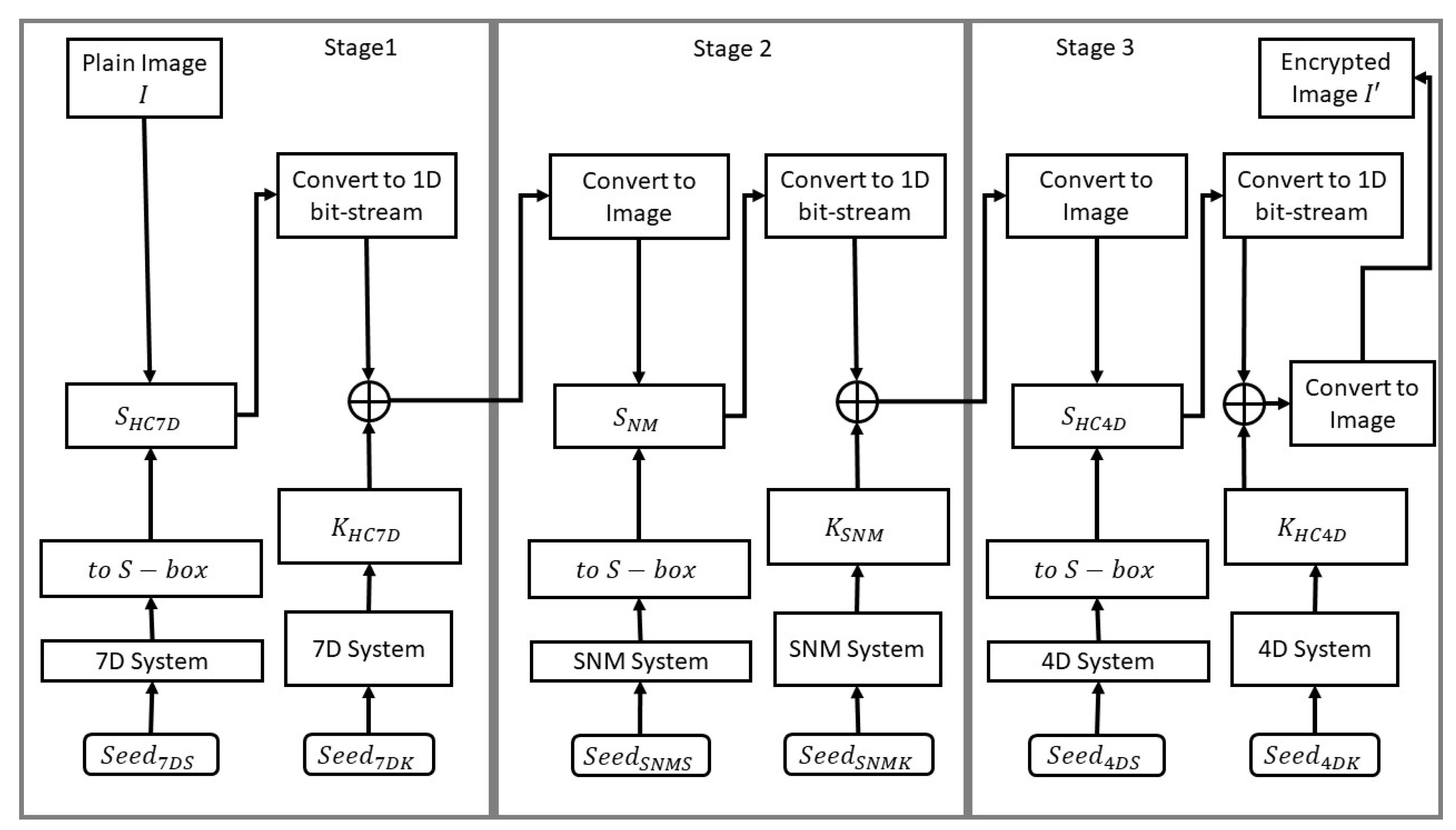
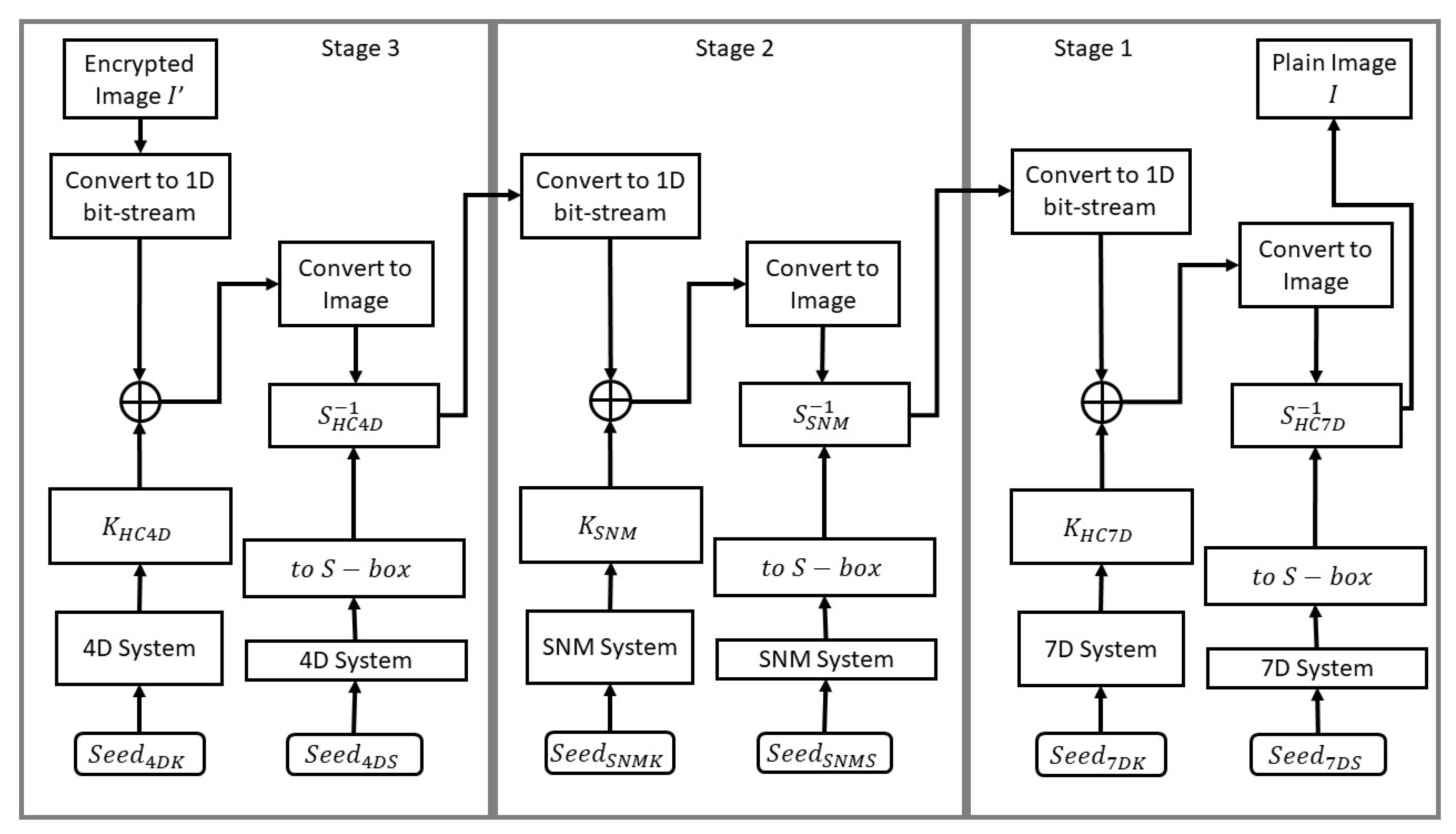
  • A chaos-based, three-stage, dual-acting image encryption framework is proposed. In every stage, a novel S-box is constructed and applied. This is followed by the generation and application of the logical XOR operation between a generated PRNG key and the image bits.
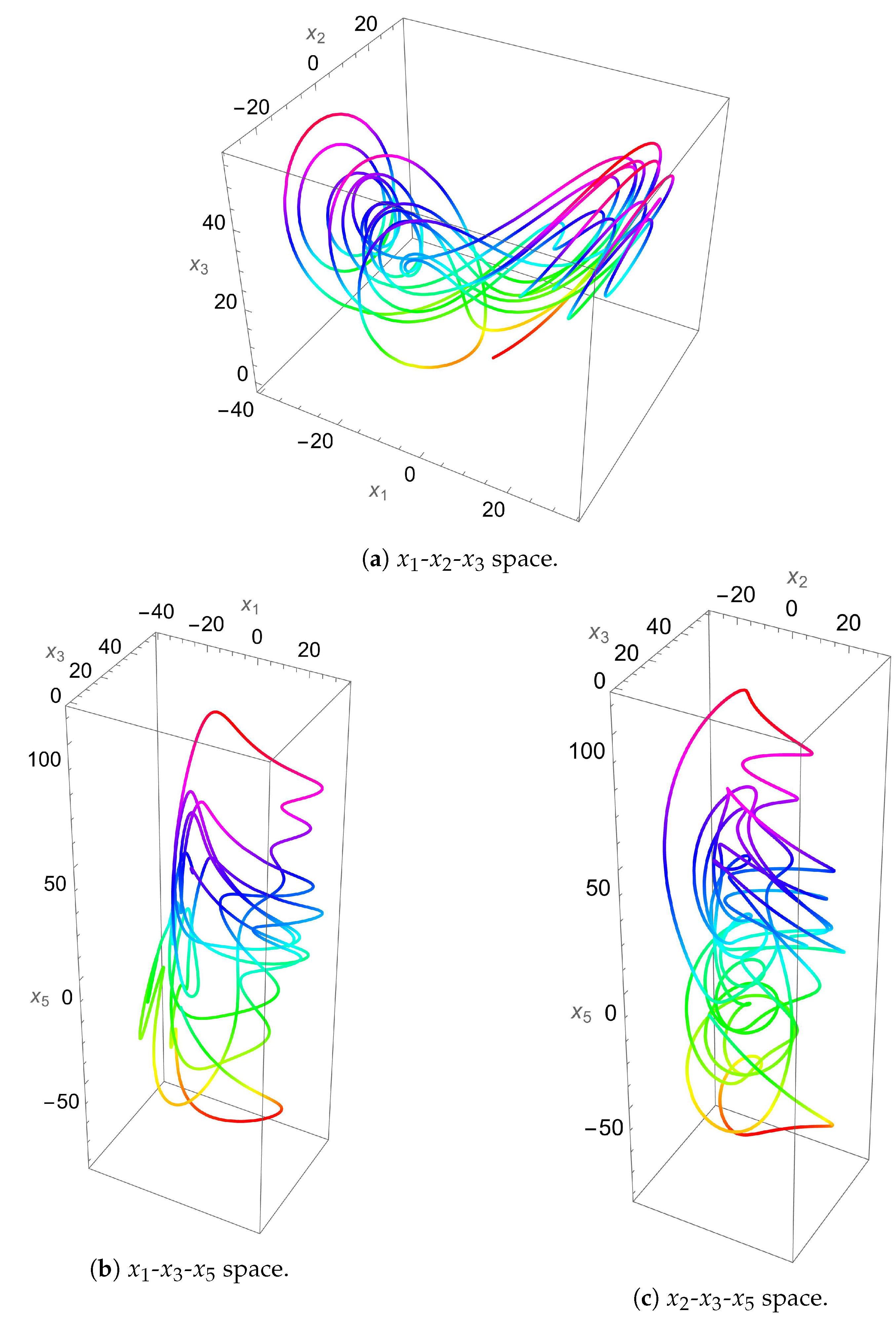
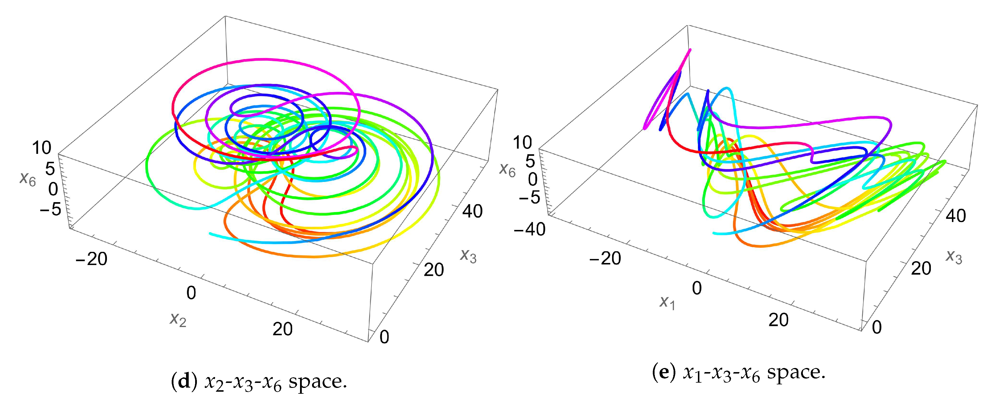
  • In the first stage, a 7D hyperchaotic system of differential equations is numerically solved and its solution is utilized both for PRNG key generation and S-box construction.
  • In the second stage, a single neuron model is numerically solved and its solution is utilized both for PRNG key generation and S-box construction.
  • In the third stage, a 4D hyperchaotic system of differential equations is numerically solved and its solution is utilized both for PRNG key generation and S-box construction.
  • With the utilization of three different systems, two of which are hyperchaotic, as well as the selection of three S-boxes that satisfy certain criteria, a rather wide key space of 2 2551 is achieved, providing sufficient resistivity to brute-force attacks.
  • The software implementation of the proposed image encryption framework making use of advanced parallel processing techniques allows for an average encryption rate of 8.54 Mbps to be achieved.
This article is organized as follows. Section 2 makes reference to the foundational systems of differential equations that are to be employed for PRNG key generation and outlines the adopted methodology for the construction of S-boxes. Section 3 introduces the image encryption and decryption processes of the proposed framework. Section 4 provides the numerical results and performance evaluation of the proposed framework. A comparative study of the state-of-the-art is also carried out in this section. Section 5 concludes this research work and provides some suggestions for possible future areas of research.

2. Preliminary Mathematical Constructs

A number of mathematical constructs are used in the proposed image encryption framework to generate the PRNG keys and S-boxes. These are presented in this section.

2.1. The Single Neuron Model

The single neuron model (SNM) is a mathematical model that describes the behavior of a single neuron with an adaptive feedback synapse. The model consists of two differential equations: one that describes the membrane potential of the neuron and one that describes the dynamics of the feedback synapse. The authors of [33] have shown that an SNM with an adaptive feedback synapse has two coexisting chaotic attractors. In this work, we make use of this SNM because of its rich, complex dynamics and its suitability with respect to inducing randomness in a simple and deterministic manner. The SNM is described as follows:
u ˙ = u τ + f ( q s ) f ( p u ) + I , s ˙ = α s + α f 2 ( p u ) ,
where α = 1 / B , while p and q are positive constants. As in [33], f ( x ) = 3 x e x p ( x 2 / 2 ) (shown in Figure 1), while I ( t ) = ϵ s i n ( ω t ) . The connected chaotic attractor of this system is plotted in Figure 2 for α = 3 , u 0 = 0.1 and s 0 = 0.5 . In Figure 2, the colors model the time factor representing initiations with cold colors and endings with hot colors. In [33], bifurcation diagrams are provided for the SNM, confirming its chaotic behavior; however, a Lyapunov exponents plot is not provided, so we provide such a plot in Figure 3. It is clear from Figure 3 that two Lyapunov exponents materialize and one of them is positive.

2.2. The 4D Hyperchaotic System

A 3D hyperchaotic system was proposed for the first time by the authors of [34]. This system was later improved by the authors of [35], who added a linear controller, resulting in the following 4D system of differential equations:
u ˙ = a ( ν u ) + e ν w , ν ˙ = c u + d ν u w + m p , w ˙ = b w + u ν , p ˙ = k u k ν ,
where u , ν , w and p are the states of the system and a , b , c , d , e , m , k are positive real parameters of the system and c R . By letting a = 15 ,   b = 43 ,   c = 1 ,   d = 16 ,   e = 5 ,   m = 5 and varying k, such that k [ 1.5 , 5.5 ] , the authors of [35] show that the system in (2) possesses hyperchaotic attractors (shown for various spaces in Figure 4) and two positive Lyapunov exponents, providing the related plots that justify their claims (see Figure 1 for the Lyapunov exponents and Figure 2 for the bifurcation diagram, in [35]). In relation to image encryption, these properties make this system a good choice for utilization in PRNG generation and subsequent S-box construction. Furthermore, as a 4D system, the system in (2) has a large number of states and parameters, which allows it to provide an excellent expansion to the key space of the proposed image encryption framework.

2.3. The 7D Hyperchaotic System

The authors in [36] presented a 7D hyperchaotic system. In their work, they propose coupling the classical Lorenz 3D system with a 6D hyperchaotic system. This 6D system is obtained through the addition of a nonlinear feedback controller to the first equation and a linear feedback controller to the second equation of the classical Lorenz 3D system. Such coupling results in a novel 7D hyperchaotic system as follows:
x 1 ˙ = a ( x 2 x 1 ) + x 4 + b x 6 , x 2 ˙ = c x 1 x 2 x 1 x 3 + x 5 , x 3 ˙ = d x 3 + x 1 x 2 , x 4 ˙ = e x 4 x 1 x 3 , x 5 ˙ = f x 2 + x 6 , x 6 ˙ = g x 1 + h x 2 , x 7 ˙ = l x 7 + m x 4 ,
where x i , i [ 1 , 7 ] are the states of the system and a , b , c , d , e , f , g , h , l and m define its parameters. The following set of values for the parameters allows the system in (3) to have seven Lyapunov exponents of which five are positive: ( a , b , c , d , e , f , g , h , l , m ) = ( 10 , 8 / 3 , 28 , 2 , 9.9 , 1 , 2 , 1 , 1 , 1 ) . Figure 5 displays the hyperchaotic attractors of this 7D system. While the system in (3) is shown to have a rather simple algebraic structure, nevertheless it exhibits complex dynamical behaviors due to possessing five positive Lyapunov exponents. The authors in [36] provide the related plots that justify their claims (see Figure 6 for the Lyapunov exponents and Figure 7 for the bifurcation diagram, in [36]). In relation to image encryption, these properties make this system a good choice for utilization in PRNG generation and subsequent S-box construction. Furthermore, being a 7D system, it has a large number of states and parameters, which allows it to provide an excellent expansion to the key space of the proposed image encryption framework.

2.4. S-Box Construction

In this work, the main aim of the S-box construction process is to involve the S-box evaluations in the generation process. In other words, the numerical values produced by the techniques used in evaluating the performance of S-boxes are utilized as part of the key space of the S-box generation step (which is reflected in the overall key space of the proposed image encryption framework). Moreover, the process adopted here makes use of the generated PRNG bitstreams discussed in Section 2.1 through Section 2.3. Accordingly, two mechanisms are applied to achieve that, with one of them being a sub-routine to the other.
Starting with the inner process, the aim is to transform a bit stream of length 2048 into an S-box. This is performed by, first, converting the 2048 bits into 256 integers. As these integers are randomly generated, they are expected to be unsorted and to contain duplicates. Hence, this set of integers is utilized as a selection function applied to a sorted set [0–255], where the selected element from the set is removed. Therefore, the selected integers are re-adjusted to the length of the sorted set using the modulus operator. As a result of the selection and the re-adjustment processes being applied sequentially, values are shifted from the sorted set (which descends in size) into the S-box, generating an S-box by the time the length of the sorted set reaches 0.
Based on the inner process discussed above, the role of the outer process is to generate a set of S-boxes, evaluate each one individually and select the S-box with performance evaluation values closest to a provided set of values. In consequence, a bitstream of size 2048 × n is needed as an input, such that n is the number of S-boxes to be generated and evaluated, and from which one is selected. Given such input, the bitstream is partitioned into sections of length 2048, transformed into S-boxes (using the inner process) and evaluated and the performance evaluation values are subtracted from the given target evaluations yielding the S-box with the smallest difference.

3. Proposed Image Encryption Framework

The encryption process is described in Section 3.1, while the decryption process is described in Section 3.2. Section 3.3 presents algorithms that are employed as part of the encryption and decryption processes.

3.1. The Encryption Process

The following sequence of steps outlines the proposed three-stage encryption process.
  • A color image I of length M and width N is chosen and the pixel values of its RGB channels are arranged as a single bitstream d, of length L d , where:
    L d = M × N × 3 × 8 .
  • Encryption stage 1: The 7D hyperchaotic system encryption key and S-box.
    (a)
    The 7D hyperchaotic system is numerically solved for the S-box seeds, then the numerical solution is utilized in Algorithm 1, resulting in an S-box S H C 7 D (shown in Table 1).
    Table 1. Seven-dimensional hyperchaotic system based S-box.
    Table 1. Seven-dimensional hyperchaotic system based S-box.
    3062124248235148352021432243851707616148
    1292253231190931536050100198751511161212
    422816711122014213892101182371682551101197
    174387815254411765105183296411221594214
    101257456162421366122147132251146281834
    6913095217521021911261137901192234082141
    3120236109162159137115451772392228617163186
    2412142200175123126811023421814522119914924
    47911798815755140255142502131381946658108
    20713117270165711874424010724322767182232211
    723327313318416317398192117230208158128225
    19681144933247391691851047731164114229204
    1891032261665746962491517818115549106244209
    2620113520139246238245180176156721931168483
    2522541955327134205879721912715012199188154
    16037216802241923359190206362038592
    (b)
    A replacement process is applied to the image I, employing S H C 7 D and resulting in image I 11 .
    I 11 = S H C 7 D ( I ) .
    (c)
    The pixels of the encrypted image I 11 are transformed into a 1D bitstream d 11 .
    (d)
    The 7D hyperchaotic system is numerically solved for the key seeds. Algorithm 2 is utilized to generate an encryption key k H C 7 D from the obtained solution, such that the length of this key is equal to L d .
    (e)
    The plaintext bitstream d 11 is XORed with the encryption key k H C 7 D .
    d 12 = d 11 k H C 7 D .
    (f)
    The resulting bitstream d 12 is transformed back into an image I 12 .
  • Encryption stage 2: The single neuron model encryption key and S-box.
    (a)
    The single neuron model is numerically solved for the S-box seeds, then the numerical solution is utilized in Algorithm 1, resulting in an S-box S S N M (shown in Table 2).
    (b)
    A replacement process is applied to image I 12 , employing S S N M , resulting in image I 21 .
    I 21 = S S N M ( I 12 ) .
    (c)
    The pixels of the encrypted image I 21 are transformed into a 1D bitstream d 21 .
    (d)
    The single neuron model is numerically solved for the key seeds. Algorithm 2 is utilized to generate an encryption key k S N M from the obtained solution, such that the length of this key is equal to L d .
    Table 2. SNM-based S-box.
    Table 2. SNM-based S-box.
    36119247239723515211747126236871124118398
    6715611279021719813915910616710117719720170
    1631091659923517321613426238171634229110212
    6915019686180115192209146203223952213712071
    189129741541142002468064621459976577176
    1086222414213292261722420898419533423
    118245116252174964048240148227547816438104
    131642051001425216921517815751662222379137
    13830207123234149221219230501751551411251292
    601872518931058317912141181171512419225
    2501851668511213010228734218253190797249
    2201472181562481611071829453208821361313363
    14523131143135202255243562810319920123270
    39122116058111233194442062102419376211191
    49881022442745578118825432128153368204
    211322431401511135516825751441841621869158
    (e)
    The bitstream of the encrypted image d 21 is XORed with the encryption key k S N M .
    d 22 = d 21 k S N M .
    (f)
    The resulting data bits d 22 are transformed back into an image I 22 .
  • Encryption stage 3: The 4D hyperchaotic system encryption key and S-box.
    (a)
    The 4D hyperchaotic system is numerically solved for the S-box seeds, then the numerical solution is utilized in Algorithm 1, resulting in an S-box S H C 4 D (shown in Table 3).
    (b)
    A replacement process is applied to image I 22 , employing S H C 4 D and resulting in image I 31 .
    I 31 = S H C 4 D ( I 22 ) .
    (c)
    The pixels of the encrypted image I 31 are transformed into a 1D bitstream d 31 .
    (d)
    The 4D hyperchaotic system is numerically solved for the key seeds. Algorithm 2 is utilized to generate an encryption key k H C 4 D from the obtained solution, such that the length of this key is equal to L d .
    (e)
    The bitstream of the encrypted image d 31 is XORed with the encryption key  k H C 4 D
    d 32 = d 31 k H C 4 D .
    (f)
    The resulting data bits d 32 are transformed back into an image I 32 . I = I 32 is the final output encrypted image.
A flow chart illustrative of the proposed three-stage encryption process is provided in Figure 6.
Table 3. Four-dimensional hyperchaotic system-based S-box.
87103129234781142197090239108223106135133116
1079122979713122838240171482150551
323522137204971613652272205820221743218
1385415753468081596023224821516125162152
22723516416317722673231861911203811224695172
1011117216025151264762531001832421639
71926931946710149140991711548877132228
4822512824324512254139184495151424414566
341856582221189361752442131303069144236142
9291972816511518841747619611061155211124
7523889181252222982372416312122485212199131
5714345184167105190173203141198207200176174
1792142422019520519214111134119230963317018
146158681231279425031206169147168180649240
178231255563719318215620811720121109118166153
1875045104102162209247233125113249159860210

3.2. The Decryption Process

The following sequence of steps outlines the proposed three-stage decryption process. They are in a reverse order to those applied in the encryption process.
  • Beginning with the three-stage encrypted image I = I 32 of length M and width N.
  • Decryption stage 3: The 4D hyperchaotic system decryption key and inverse S-box.
    (a)
    The pixel values of the encrypted image I 32 are transformed into a bitstream d 32 .
    (b)
    The encrypted data bits d 32 are XORed with the decryption key k H C 4 D .
    d 31 = d 32 k H C 4 D .
    (c)
    The resulting encrypted data bits d 31 are converted into an image I 31 .
    (d)
    A reverse replacement process is applied to image I 31 , employing S H C 4 D 1 and resulting in image I 22
    I 22 = S H C 4 D 1 ( I 31 ) .
  • Decryption stage 2: The single neuron model decryption key and inverse S-box.
    (a)
    The pixel values of the encrypted image I 22 are transformed into a bitstream d 22 .
    (b)
    The encrypted data bits d 22 are XORed with the decryption key k S N M .
    d 21 = d 22 k S N M .
    (c)
    The resulting encrypted data bits d 21 are converted into an image I 21 .
    (d)
    A reverse replacement process is applied to the image I 21 , employing S S N M 1 and resulting in image I 12 .
    I 12 = S S N M 1 ( I 21 ) .
  • Decryption stage 1: The 7D hyperchaotic system decryption key and inverse S-box.
    (a)
    The pixel values of the encrypted image I 12 are transformed into a bitstream d 12 .
    (b)
    The encrypted data bits d 12 are XORed with the decryption key k H C 7 D .
    d 11 = d 12 k H C 7 D .
    (c)
    The resulting encrypted data bits d 11 are converted into an image I 11 .
    (d)
    A reverse replacement process is applied to the image I 11 , employing S H C 7 D 1 and resulting in a plain image I.
    I = S H C 7 D 1 ( I 11 ) .
A flow chart illustrative of the proposed three-stage decryption process is provided in Figure 7.

3.3. Utilized Algorithms

Algorithm 1 describes the generation of an S-box given a pseudo-random bitstream generated using one of the three PRNGs proposed earlier in Section 2. As discussed in Section 2.4, by treating the evaluation values of the S-box as part of the key space, Algorithm 1 attempts to achieve a certain set of provided values for S-box evaluations. The approach towards that is to generate an agreed upon number of S-boxes (which is a part of the key space as well), then each S-box is evaluated separately and the chosen S-box is the one with performance evaluation values closer to the target values. Accordingly, it may come naturally to always provide optimal S-box evaluation values for every attempt at S-box generation. Nevertheless, to fulfill the need to complicate any cryptanalysis efforts, other sub-optimal values may be provided, resulting in the generation of different S-boxes. Such a decision would not affect the overall encryption process much as each generated S-box is only one component out of many stages. Therefore, the performance evaluation of the encryption process is based on the integration of all the components in all three stages of the proposed encryption framework. Algorithm 2 elaborates on the procedure for generating a PRNG bitstream given the solution of a chaotic system.
Algorithm 1 Generate an S-box given a bitstream b P R N G , the number of S-box trials n, target performance evaluation values M = { N L , S A C , B I C , L A P , D A P } and a bitstream b P R N G (an adaptation from that proposed in [12])
  • S b i t s = P a r t i t t i o n ( b P R N G , 2048 )
  • S b o x r e s = []
  • M r e s = M
  • For each S i S b i t s :
    (a)
    Z i = T o D e c i m a l ( P a r t i t i o n ( S i , 8 ) )
    (b)
    L i = [ 0 255 ]
    (c)
    For each U j Z i :
    •        L o c j = U j % L e n g t h ( L i )
    •       A p p e n d ( L i [ L o c j ] , S b o x i )
    •      D e l e t e ( L i [ L o c j ] , L i )
    (d)
    M i = { N L ( S b o x i ) , S A C ( S b o x i ) , B I C ( S b o x i ) , L A P ( S b o x i ) , D A P ( S b o x i ) }
    (e)
    If | M i M | < M r e s :
    •        M r e s = | M i M |
    •       S b o x r e s = S b o x i
  • Return S b o x r e s
Algorithm 2 Generate a PRNG bitstream given a chaotic system S of k dimensions and the number of needed bits n (first proposed in [12])
  • Solve S for the size of n k + 1 and the sufficient seeds producing the list of lists { L 1 , L 2 , , L k } where L i is the solution for dimension i
  • Convert the list of lists into a 1D list as follows:
    L = { L 1 [ 1 ] , L 2 [ 1 ] , , L k [ 1 ] , L 1 [ 2 ] , L 2 [ 2 ] , , L k [ 2 ] , }
  • Drop the last | L | n elements from L
  • L b i t s [ i ] = 1 , if L [ i ] > M e d i a n ( L ) 0 , otherwise

4. Numerical Results and Performance Evaluation

The performance of the proposed image encryption framework is provided in this section. A number of common performance evaluation metrics from the literature are utilized in this work [2,7,12]. Their mathematical expressions are provided in Table 4. The tests carried out aim to gauge the security, robustness and efficiency of the proposed framework in eradicating any identifiable information from the output encrypted images, such that they are completely asymmetric to their plaintext versions. The proposed framework is implemented on a machine running macOS Catalina v.10.15.7 with a 2.9 GHz 6-Core Intel® CoreTM i9 and 32 GB of 2400 MHz DDR4 RAM. The software of choice is Wolfram Mathematica® v.13.2. Common images found in the state-of-the-art are also utilized in this work to allow for a comparative analysis. All images are 256 pixels in length and 256 pixels in width, unless stated otherwise.

4.1. Visual and Visual-Statistical Analyses

The first measure employed for testing the output encrypted images is an examination through the human visual system (HVS). It is clear from Figure 8, Figure 9, Figure 10, Figure 11, Figure 12 and Figure 13 that no relation whatsoever can be observed between the plain images and their encrypted versions (i.e., complete asymmetry is achieved). The same can be noticed for their respective histograms. The histograms of the encrypted images depict a rather uniform distribution of values, which characterizes excellent encryption.

4.2. Statistical Analyses

The statistical analysis starts with the computation of the mean squared error (MSE), the peak signal-to-noise ratio (PSNR) and the maximum absolute error (MAE) between input plain images and output encrypted images. These are quantitative metrics that measure the degree of change between two images and are very common in the literature on image encryption. The computed values are reported in Table 5, Table 6 and Table 7, respectively. It is clear from each of the tables that the computed values for the proposed image encryption algorithm are comparable or superior to the state-of-the-art, with high MSE and MAE values and thus low PSNR values, indicating excellent scrambling and randomization performance of the proposed image encryption framework.
As for Shannon’s information entropy, Table 8 displays the computed values for various encrypted images and compares those values with the state-of-the-art. Excellent entropy performance of 7.999 is showcased for the proposed image encryption framework, being superior or comparable to counterpart algorithms.
The pixel cross-correlation coefficient ρ is a measure of the linear dependency between neighboring pixel values in an image. It quantifies how well the encryption process has scrambled the pixels and eliminated any spatial relationships. For a well-encrypted image, ρ should have a value close to 0, indicating little or no correlation between adjacent pixel values. Table 9 provides the ρ values for various images, each computed in three directions (horizontal, vertical and diagonal). While the plain images have ρ values close to 1, their encrypted versions have ρ values close to 0. A visual illustration of this metric is provided as a set of 2D plots in Figure 14 for the House image, as well as in Figure 15, Figure 16 and Figure 17, respectively, for each of its RGB channels, while sub-figures (c) and (f) of Figure 13 provide 3D plots of the same metric for the House image. It is clear that the plots of encrypted images exhibit a uniform distribution of values, unlike those of their plain versions. Table 10 and Table 11 display a comparison of ρ with the state-of-the-art, utilizing the Lena image and each of its RGB channels, respectively. The computed ρ values are shown to be near 0, as is the case in the state-of-the-art, in each of the tables.
Another interesting manner of examining the pixel cross-correlation among pixels would be to do so in the Fourier domain by generating the discrete Fourier transform (DFT) of the plain and encrypted House images, as shown in sub-figures (b) and (e) of Figure 13 and visually examining them. The presence of a bright star-like shape at the center of the DFT plain image is characteristic of a normal plain image which has pixels depicting edges and corners. This is unlike the DFT of the encrypted image, which lacks any identifying visual characteristics.
Since randomness is an integral measure of any image encryption algorithm, an objective quantitative measure of it should be utilized. This is best carried out through a National Institute of Standards and Technology (NIST) SP 800 analysis [37]. In brief, a NIST analysis tests a bitstream for a number of characteristics, including its randomness, quantifies its randomness and detects structural weaknesses. Such an analysis provides empirical evidence of the suitability of a PRNG’s use in cryptography applications. Table 12 presents the results of a NIST analysis carried out on a bitstream depicting the data of an encrypted Girl image. All NIST tests are successfully passed, with scored p-values greater than 0.01 .
Table 5. MSE values for various images, for the proposed framework and the state-of-the-art.
ImageProposed[7][13][38][15][6][19][12]
Lena 8890.05 9112.1 8926.96 10,869.73 4859.03 8888.88 N/A 8912.4
Mandrill 8345.25 8573.38 8290.84 10,930.33 6399.05 8295.21 N/A 8320.41
Peppers10,074.010,298.710,045.1N/A 7274.44 10,092.3N/A10,065.4
House 8361.44 8427.04 8351.64 N/AN/AN/AN/A 8395.53
House2 9190.27 9374.65 N/AN/AN/AN/AN/A 9142.54
Girl12,152.812,450.9N/AN/AN/AN/AN/A12,104.2
Sailboat10,063.3N/AN/AN/AN/AN/AN/A10,071.9
Tree 9931.63 N/AN/AN/AN/AN/AN/A 9873.24
Average 9626.09 9706.13 8903.64 10,900 6177.51 9092.13 N/A 9610.65
Table 6. PSNR values for various images, for the proposed framework and the state-of-the-art.
ImageProposed[7][13][38][15][6][19][12]
Lena 8.64176 8.53462 8.6237 7.7677 11.3 8.64233 8.5674 8.63086
Mandrill 8.91641 8.79929 8.9448 7.7447 10.10 8.94253 10.0322 8.92936
Peppers 8.09877 8.00296 8.11128 N/A 9.55 N/AN/A 8.10248
House 8.90799 8.87405 8.91309 N/AN/AN/AN/A 8.89032
House2 8.49752 8.41125 N/AN/AN/AN/AN/A 8.52013
Girl 7.28403 7.17879 N/AN/AN/AN/AN/A 7.30144
Sailboat 8.10339 N/AN/AN/AN/AN/AN/A 8.0997
Tree 8.1606 N/AN/AN/AN/AN/AN/A 8.18621
Average 8.32631 8.30016 8.64822 7.7562 10.3167 8.79243 9.2998 8.33256
Table 7. MAE values for various images, for the proposed framework and the state-of-the-art.
ImageProposed[7][6][38][39][19][12]
Lena 77.409 78.3564 77.3752 87 77.35 77.96 77.4877
Peppers 82.0156 82.3273 81.7740 N/A 74.71 N/A 81.9832
Mandrill 75.3335 81.913 75.1659 92 73.91 67.85 75.1632
House 75.3132 N/AN/AN/AN/AN/A 75.4983
House2 78.5675 N/AN/AN/AN/AN/A 78.3327
Girl 90.1646 N/AN/AN/AN/AN/A 89.9807
Sailboat 82.0101 N/AN/AN/AN/AN/A 82.1003
Tree 81.4948 N/AN/AN/AN/AN/A 81.1623
Average 80.9993 80.8656 78.105 89.5 75.3233 72.905 80.2136
Table 8. Entropy values for various images, for the proposed framework and the state-of-the-art.
ImageProposed[7][13][38][40][15][6][19][12]
Lena 7.999 7.9856 7.999 7.999 7.997 7.996 7.997 7.9972 7.99887
Mandrill 7.999 7.9905 7.999 7.999 7.999 N/A 7.996 7.9969 7.99866
Peppers 7.999 7.9951 7.999 7.9991 N/A 7.997 7.9969 N/A 7.99834
House 7.999 7.9577 7.999 N/AN/AN/AN/AN/A 7.99729
House2 7.999 7.9847 N/AN/AN/AN/AN/AN/A 7.99848
Girl 7.999 7.9789 N/AN/AN/AN/AN/AN/A 7.99477
Sailboat 7.999 N/AN/AN/AN/AN/AN/AN/A 7.99875
Tree 7.999 N/AN/AN/AN/AN/AN/AN/A 7.99713
Average 7.999 7.98208 7.999 7.999 7.99903 7.9965 7.99663 7.99705 7.99711
Table 9. Correlation coefficient values for various plain and encrypted images.
Plain ImageEncrypted Image
Correlation CoefficientCorrelation Coefficient
ImageHorizontalDiagonalVerticalHorizontalDiagonalVertical
Lena 0.938611 0.913175 0.96833 0.00180128 0.000991502 0.00018608
Mandrill 0.848778 0.750624 0.79088 0.00713777 0.00152782 0.00491305
Peppers 0.959422 0.930426 0.966795 0.00301689 0.00419115 0.00012237
House 0.978232 0.936044 0.952926 0.00147997 0.00286442 0.0015624
House2 0.907075 0.850782 0.923091 0.000841531 0.00214171 0.00626431
Girl 0.974013 0.951471 0.965671 0.000841531 0.00214171 0.00626431
Sailboat 0.952381 0.0 . 919872 0.950138 0.00608092 0.00279574 0.00170383
Tree 0.968153 0.929967 0.94515 0.00226616 0.00137505 0.00332063
Table 10. Correlation coefficient values comparison with the state-of-the-art, for an encrypted Lena image.
AlgorithmHorizontalDiagonalVertical
Proposed 0.00180128 0.000991502 0.000186079
[6] 0.002287 0.00132 0.00160
[7] 0.003265 0.00413 0.002451
[12] 0.0064113 0.0015143 0.000568333
[17] 0.00144 0.00151 0.00795
[19] 0.0061 0.0018 0.0067
[22] 0.000199 0.003705 0.000924
[38] 0.0054 0.0054 0.0016
Table 11. Color channel separated correlation coefficient value comparison with the state-of-the-art, for the Lena image.
ChannelDirectionPlain ImageEncrypted Image[23][24][25][6]
RedHorizontal 0.952474 0.00266725 0.001365 0.0021 0.9568 0.00364
Diagonal 0.928029 0.00564219 0.000232 0.0026 0.0075 0.00016
Vertical 0.975913 0.0008351 0.004776 0.0018 0.0376 0.000697
GreenHorizontal 0.935628 0.00307568 0.003294 0.0006 0.0020 0.000118
Diagonal 0.910534 0.0020740 0.004807 0.0001 0.0046 0.00177
Vertical 0.966647 0.0011823 0.000579 0.0004 0.0013 0.0011
BlueHorizontal 0.917439 0.00046821 0.002060 0.005 0.0071 0.00164
Diagonal 0.888482 0.0025489 0.004043 0.0104 0.0009 0.00523
Vertical 0.947961 0.0053944 0.000194 0.001 0.0423 0.006041
Table 12. NIST analysis on Girl encrypted image.
Test NameValueRemarks
Frequency 0.425242 Success
Block Frequency 0.276783 Success
Run 0.714157 Success
Longest run of ones 0.932530 Success
Rank 0.138292 Success
Spectral FFT 0.846825 Success
Non overlapping 0.613084 Success
Overlapping 0.449023 Success
Universal 0.687511 Success
Linear complexity 0.241374 Success
Serial 0.850353 Success
Approximate Entropy 0.030357 Success
Cumulative sum (forward) 0.503876 Success
Cumulative sum (reverse) 0.783156 Success

4.3. Differential Attack Analysis

A differential attack analysis is a type of cryptanalytic attack on encryption algorithms where an attacker analyzes the effect of specific changes in the input plaintext on the output ciphertext. For example, the change of a single bit in the input plain image. By analyzing these differences, the attacker may be able to deduce information about the key or algorithm used. Two tests are commonly employed in the literature for such an analysis: The number of pixel change ratios (NPCR) for pixel-by-pixel comparison and the unified averaged change intensity (UACI) for the evaluation of the mean average difference [41] have ideal values for well-encrypted images of 100 % and 33.33 % , respectively. The mathematical expressions corresponding to each of those metrics are provided in Table 4. The computed NPCR and UACI values for various images are displayed in Table 13, with achieved average values of 99.6186 % and 31.4857 % , respectively, reflecting excellent performance. Table 14 compares the computed values with the state-of-the-art for the RGB channels of various images. As expected, a comparable performance is achieved. Moreover, Table 15, displays another comparison with counterpart algorithms for the Lena image. Once again, a comparable performance is achieved.

4.4. Key Space Analysis

It is of vital importance to carry out a key space analysis of any image encryption technique. Such an analysis quantifies how much information (in bits) is required to specify an encryption key. The more bits needed, the larger the key space. Consequently, a large key space makes brute-force attacks infeasible. The larger the number of possible keys, the greater the resources and time required to try every key. This helps ensure encryption is secure against brute-force cracking. In the proposed image encryption framework, the attained key space is vast, mainly due to the utilization of the hyperchaotic maps. The 4D hyperchaotic map employs four initial values and seven constants; the 7D hyperchaotic map employs seven initial conditions and 10 constants; and the SNM employs a total of five variables only. For each of the three S-boxes, five specific values for the metrics are chosen. This gives a total of 4 + 7 + 7 + 10 + 5 + 3 × 5 = 48 variables in the computation of the key space. The computer and software package used to implement the proposed image encryption framework have a machine precision of 10 16 . Ultimately, this gives a key space of 10 48 × 16 = 10 768 2 2551 . This computed value far surpasses the threshold suggested earlier in the literature [45], of 2 100 , for successful resistance to brute-force attacks. A comparative analysis is carried out with the state-of-the-art in Table 16, showcasing the superior key space of the proposed image encryption framework.

4.5. Histogram Dependency Tests

In this testing perspective, the histograms of the plain and encrypted images are statistically compared in order to show the lack of statistical dependence between the two. Table 17 shows the five utilized tests (Blomqvist β , Goodman–Kruskal γ , Kendall τ , Spearman ρ and Pearson r) and their mathematical expressions [46]. Table 18 demonstrates the results of applying these tests to a variety of images. As seen in the table, most of the resulting values approach 0, which shows a lack of any statistical dependency between every plain image and its encrypted version.

4.6. Execution Time Analysis

The execution time of an image encryption algorithm is an important metric, as it allows for a comparison of the efficiency and performance of different algorithms as well as an estimation of the computational resources required for software and hardware implementation. Moreover, an analysis of the execution time reveals the applicability of an algorithm for real-time image encryption applications. The software implementation of the proposed image encryption framework is carried out over Wolfram Mathematica® v.13.2. The algorithm’s execution time is optimized through parallel processing over the six cores of the Intel® CoreTM i9 processor. The full details of the computing environment are provided in the first paragraph of Section 4. Table 19 reports the attained execution times of the Lena image at various dimensions. These times result in an average encryption rate of 8.54 Mbps. Moreover, Table 20 provides a comparative analysis of the state-of-the-art algorithms. The superiority of the proposed framework is clear, with the attained encryption times being much shorter in comparison to their counterparts, irrespective of the machine specifications.

4.7. S-Box Performance Analysis

The proposed S-boxes are evaluated in this section independently of the proposed framework’s performance as a whole. This is because an S-box is a consistent element that is nearly always at the core of image encryption algorithms and is tasked with applying Shannon’s property of confusion. In order to evaluate the ability of an S-box to cause confusion, five metrics are commonly computed [47]. These are the non-linearity (NL), linear approximation probability (LAP), differential approximation probability (DAP), bit independence criterion (BIC) and strict avalanche criterion (SAC). They are calculated for the proposed S-boxes (shown in Table 1, Table 2 and Table 3) and compared to those reported in the state-of-the-art as well as to the ideal values, in Table 21. While all three proposed S-boxes exhibit performances comparable to counterpart algorithms from the literature, it is clear that the S-boxes constructed from the hyperchaotic functions perform better than the S-box constructed from the SNM. This is an advantage of hyperchaotic functions [48]. As in [12] and as described earlier in Section 3.3, upon designing and constructing each of the proposed S-boxes, the aim is not to reach the ideal values of the metrics but rather to reach a set of target metrics that are in close proximity to the ideal ones. This was carried out so as to include this set of target values as part of the key space, expanding it by 5 × 3 = 15 variables and allowing it to reach a key space of 2 2551 , as explained earlier in Section 4.4.

5. Conclusions and Future Works

This work attempted to propose a novel framework for image encryption, capitalizing on the inherent characteristics of hyperchaotic functions and the simplicity of the single neuron model. Encryption was carried out over three stages, where in each stage the solution of one of the systems was numerically computed and used to generate a PRNG and construct an S-box. Next, the S-box was applied to scramble the image data, while an XOR operation with the encryption key was applied to randomize it. The main advantages of the proposed framework could be summarized as attaining a vast key space of 2 2551 and a high encryption rate of 8.54 Mbps. Reaching such a key space is attributed to the usage of hyperchaotic functions, while the efficiency of the framework is attributed to the optimization of its software implementation and making use of parallel processing over six cores. Moreover, the proposed framework was tested against an array of security tests, both quantitative and qualitative in nature and was shown to exhibit comparable or even superior performance, in comparison to the state-of-the-art. Average achieved values for the quantitative metrics include MSE of 9626, PSNR of 8.3 dB, MAE of 80.99 , entropy of 7.999 , NPCR of 99.6 % and UACI of 31.49 % .
Future research efforts could be dedicated to attempting to improve the efficiency of the proposed image encryption framework even more. This could be carried out through an enhanced parallel processing architecture by running it over a network of connected machines or, better yet, by implementing it in hardware (i.e., on an FPGA, for example).

Author Contributions

Conceptualization, W.A., Y.-L.C. and L.Y.P.; methodology, W.A. and M.G.; software, W.A. and M.G.; validation, W.A.; writing—original draft preparation, W.A. and M.G.; writing—review and editing, W.A., Y.-L.C. and L.Y.P.; visualization, W.A.; supervision, W.A., Y.-L.C. and L.Y.P. All authors have read and agreed to the published version of the manuscript.

Funding

This research was funded by the National Science and Technology Council in Taiwan, grant number NSTC-109-2628-E-027-004–MY3, NSTC-111-2218-E-027-003 and NSTC-111-2622-8-027-009 and the Ministry of Education of Taiwan, official document number 1112303249.

Data Availability Statement

Not applicable.

Conflicts of Interest

The authors declare no conflict of interest.

Abbreviations

The following abbreviations are used in this manuscript:
CACellular Automata
DNADeoxyribonucleic acid
HVSHuman Visual System
MAEMaximum absolute error
MSEMean Square Error
NISTNational Institute of Standards and Technology
NPCRNumber of Pixel Changing Ratio
PRNGPseudo-Random Number Generation
PSNRPeak Signal-to-Noise Ratio
S-boxSubstitution box
SNMSingle Neuron Model
SPNSubstitution-Permutation Network
UACIUnified Averaged Change Intensity

References

  1. Hosny, K.M.; Kamal, S.T.; Darwish, M.M. A color image encryption technique using block scrambling and chaos. Multimed. Tools Appl. 2022, 81, 505–525. [Google Scholar] [CrossRef]
  2. Alexan, W.; Elkandoz, M.; Mashaly, M.; Azab, E.; Aboshousha, A. Color Image Encryption through Chaos and KAA Map. IEEE Access 2023, 11, 11541–11554. [Google Scholar] [CrossRef]
  3. Alexan, W.; Mamdouh, E.; ElBeltagy, M.; Ashraf, A.; Moustafa, M.; Al-Qurashi, H. Social Engineering and Technical Security Fusion. In Proceedings of the 2022 International Telecommunications Conference (ITC-Egypt), Alexandria, Egypt, 26–28 July 2022; pp. 1–5. [Google Scholar]
  4. Jasra, B.; Moon, A.H. Color image encryption and authentication using dynamic DNA encoding and hyper chaotic system. Expert Syst. Appl. 2022, 206, 117861. [Google Scholar] [CrossRef]
  5. Fang, J.; Jiang, M.; Yin, N.; Wei, D.; Zhang, Y. An image block encryption algorithm based on hyperchaotic system and DNA encoding. Multimed. Tools Appl. 2022, 81, 17245–17262. [Google Scholar] [CrossRef]
  6. Alexan, W.; ElBeltagy, M.; Aboshousha, A. Rgb image encryption through cellular automata, s-box and the lorenz system. Symmetry 2022, 14, 443. [Google Scholar] [CrossRef]
  7. Gabr, M.; Younis, H.; Ibrahim, M.; Alajmy, S.; Khalid, I.; Azab, E.; Elias, R.; Alexan, W. Application of DNA Coding, the Lorenz Differential Equations and a Variation of the Logistic Map in a Multi-Stage Cryptosystem. Symmetry 2022, 14, 2559. [Google Scholar] [CrossRef]
  8. Gabr, M.; Alexan, W.; Moussa, K.; Maged, B.; Mezar, A. Multi-Stage RGB Image Encryption. In Proceedings of the 2022 International Telecommunications Conference (ITC-Egypt), Alexandria, Egypt, 26–28 July 2022; pp. 1–6. [Google Scholar]
  9. Shannon, C.E. Communication theory of secrecy systems. Bell Syst. Tech. J. 1949, 28, 656–715. [Google Scholar] [CrossRef]
  10. Elqusy, A.S.; Essa, S.E.; El-Sayed, A. Key management techniques in wireless sensor networks. Commun. Appl. Electron. (CAE) 2017, 7, 8–18. [Google Scholar]
  11. Shariatzadeh, M.; Rostami, M.J.; Eftekhari, M. Proposing a novel Dynamic AES for image encryption using a chaotic map key management approach. Optik 2021, 246, 167779. [Google Scholar] [CrossRef]
  12. Alexan, W.; Alexan, N.; Gabr, M. Multiple-Layer Image Encryption Utilizing Fractional-Order Chen Hyperchaotic Map and Cryptographically Secure PRNGs. Fractal Fract. 2023, 7, 287. [Google Scholar] [CrossRef]
  13. Alexan, W.; ElBeltagy, M.; Aboshousha, A. Image Encryption Through Lucas Sequence, S-Box and Chaos Theory. In Proceedings of the 2021 8th NAFOSTED Conference on Information and Computer Science (NICS), Hanoi, Vietnam, 21–22 December 2021; pp. 77–83. [Google Scholar]
  14. Matouk, A.; Lahcene, B. Rich complex dynamics in new fractional-order hyperchaotic systems using a modified Caputo operator based on the extended Gamma function. Partial. Differ. Equ. Appl. Math. 2022, 6, 100458. [Google Scholar] [CrossRef]
  15. Younas, I.; Khan, M. A new efficient digital image encryption based on inverse left almost semi group and Lorenz chaotic system. Entropy 2018, 20, 913. [Google Scholar] [CrossRef]
  16. Alexan, W.; ElBeltagy, M.; Aboshousha, A. Lightweight image encryption: Cellular automata and the lorenz system. In Proceedings of the 2021 International Conference on Microelectronics (ICM), New Cairo City, Egypt, 19–22 December 2021; pp. 34–39. [Google Scholar]
  17. Elkandoz, M.T.; Alexan, W. Image encryption based on a combination of multiple chaotic maps. Multimed. Tools Appl. 2022, 81, 25497–25518. [Google Scholar] [CrossRef]
  18. ElBeltagy, M.; Alexan, W.; Elkhamry, A.; Moustafa, M.; Hussein, H.H. Image Encryption through Rössler System, PRNG S-Box and Recamán’s Sequence. In Proceedings of the 2022 IEEE 12th Annual Computing and Communication Workshop and Conference (CCWC), Las Vegas, NV, USA, 26–29 January 2022; pp. 0716–0722. [Google Scholar]
  19. Iqbal, N.; Naqvi, R.A.; Atif, M.; Khan, M.A.; Hanif, M.; Abbas, S.; Hussain, D. On the Image Encryption Algorithm Based on the Chaotic System, DNA Encoding and Castle. IEEE Access 2021, 9, 118253–118270. [Google Scholar] [CrossRef]
  20. ur Rehman, A.; Liao, X.; Ashraf, R.; Ullah, S.; Wang, H. A color image encryption technique using exclusive-OR with DNA complementary rules based on chaos theory and SHA-2. Optik 2018, 159, 348–367. [Google Scholar] [CrossRef]
  21. Yang, B.; Liao, X. A new color image encryption scheme based on logistic map over the finite field ZN. Multimed. Tools Appl. 2018, 77, 21803–21821. [Google Scholar] [CrossRef]
  22. Wang, Y.; Wu, C.; Kang, S.; Wang, Q.; Mikulovich, V. Multi-channel chaotic encryption algorithm for color image based on DNA coding. Multimed. Tools Appl. 2020, 79, 18342. [Google Scholar] [CrossRef]
  23. Zhang, Y.Q.; He, Y.; Li, P.; Wang, X.Y. A new color image encryption scheme based on 2DNLCML system and genetic operations. Opt. Lasers Eng. 2020, 128, 106040. [Google Scholar] [CrossRef]
  24. Jithin, K.; Sankar, S. Colour image encryption algorithm combining, Arnold map, DNA sequence operation and a Mandelbrot set. J. Inf. Secur. Appl. 2020, 50, 102428. [Google Scholar] [CrossRef]
  25. Rehman, A.U.; Firdous, A.; Iqbal, S.; Abbas, Z.; Shahid, M.M.A.; Wang, H.; Ullah, F. A Color Image Encryption Algorithm Based on One Time Key, Chaos Theory and Concept of Rotor Machine. IEEE Access 2020, 8, 172275–172295. [Google Scholar] [CrossRef]
  26. Li, B.; Liao, X.; Jiang, Y. A novel image encryption scheme based on logistic map and dynatomic modular curve. Multimed. Tools Appl. 2018, 77, 8911–8938. [Google Scholar] [CrossRef]
  27. Hu, X.; Wei, L.; Chen, W.; Chen, Q.; Guo, Y. Color image encryption algorithm based on dynamic chaos and matrix convolution. IEEE Access 2020, 8, 12452–12466. [Google Scholar] [CrossRef]
  28. Zhang, X.; Wang, L.; Wang, Y.; Niu, Y.; Li, Y. An image encryption algorithm based on hyperchaotic system and variable-step Josephus problem. Int. J. Opt. 2020, 2020, 6102824. [Google Scholar] [CrossRef]
  29. Gong, L.; Qiu, K.; Deng, C.; Zhou, N. An image compression and encryption algorithm based on chaotic system and compressive sensing. Opt. Laser Technol. 2019, 115, 257–267. [Google Scholar] [CrossRef]
  30. Lai, Q.; Hu, G.; Erkan, U.; Toktas, A. A novel pixel-split image encryption scheme based on 2D Salomon map. Expert Syst. Appl. 2023, 213, 118845. [Google Scholar] [CrossRef]
  31. Erkan, U.; Toktas, A.; Lai, Q. 2D hyperchaotic system based on Schaffer function for image encryption. Expert Syst. Appl. 2023, 213, 119076. [Google Scholar] [CrossRef]
  32. Song, W.; Fu, C.; Zheng, Y.; Tie, M.; Liu, J.; Chen, J. A parallel image encryption algorithm using intra bitplane scrambling. Math. Comput. Simul. 2023, 204, 71–88. [Google Scholar] [CrossRef]
  33. Li, C.; Chen, G. Coexisting chaotic attractors in a single neuron model with adapting feedback synapse. Chaos Solitons Fractals 2005, 23, 1599–1604. [Google Scholar] [CrossRef]
  34. Qi, G.; van Wyk, B.J.; van Wyk, M.A. A four-wing attractor and its analysis. Chaos Solitons Fractals 2009, 40, 2016–2030. [Google Scholar] [CrossRef]
  35. Cui, N.; Li, J. A new 4D hyperchaotic system and its control. AIMS Math. 2023, 8, 905–923. [Google Scholar] [CrossRef]
  36. Yang, Q.; Zhu, D.; Yang, L. A new 7D hyperchaotic system with five positive Lyapunov exponents coined. Int. J. Bifurc. Chaos 2018, 28, 1850057. [Google Scholar] [CrossRef]
  37. Bassham, L.E.I.; Rukhin, A.L.; Soto, J.; Nechvatal, J.R.; Smid, M.E.; Barker, E.B.; Leigh, S.D.; Levenson, M.D.; Vangel, M.; Banks, D.L.; et al. A Statistical Test Suite for Random and Pseudorandom Number Generators for Cryptographic Applications; Revised 800-22; National Institute of Standards and Technology: Boulder, CO, USA, 2010.
  38. Khan, M.; Masood, F. A novel chaotic image encryption technique based on multiple discrete dynamical maps. Multimed. Tools Appl. 2019, 78, 26203–26222. [Google Scholar] [CrossRef]
  39. Khan, M.; Shah, T. An efficient chaotic image encryption scheme. Neural Comput. Appl. 2015, 26, 1137–1148. [Google Scholar] [CrossRef]
  40. Liu, H.; Zhao, B.; Huang, L. Quantum image encryption scheme using Arnold transform and S-box scrambling. Entropy 2019, 21, 343. [Google Scholar] [CrossRef]
  41. Wu, Y.; Noonan, J.; Agaian, S. NPCR and UACI randomness tests for image encryption. Cyber J. Multidiscip. J. Sci. Technol. J. Sel. Areas Telecommun. (JSAT) 2011, 1, 31–38. [Google Scholar]
  42. Slimane, N.B.; Aouf, N.; Bouallegue, K.; Machhout, M. A novel chaotic image cryptosystem based on DNA sequence operations and single neuron model. Multimed. Tools Appl. 2018, 77, 30993–31019. [Google Scholar] [CrossRef]
  43. Paul, L.; Gracias, C.; Desai, A.; Thanikaiselvan, V.; Suba Shanthini, S.; Rengarajan, A. A novel colour image encryption scheme using dynamic DNA coding, chaotic maps and SHA-2. Multimed. Tools Appl. 2022, 81, 37873–37894. [Google Scholar] [CrossRef]
  44. Wu, X.; Kurths, J.; Kan, H. A robust and lossless DNA encryption scheme for color images. Multimed. Tools Appl. 2018, 77, 12349–12376. [Google Scholar] [CrossRef]
  45. Alvarez, G.; Li, S. Some basic cryptographic requirements for chaos-based cryptosystems. Int. J. Bifurc. Chaos 2006, 16, 2129–2151. [Google Scholar] [CrossRef]
  46. Asuero, A.G.; Sayago, A.; González, A. The correlation coefficient: An overview. Crit. Rev. Anal. Chem. 2006, 36, 41–59. [Google Scholar] [CrossRef]
  47. Mahmood Malik, M.S.; Ali, M.A.; Khan, M.A.; Ehatisham-Ul-Haq, M.; Shah, S.N.M.; Rehman, M.; Ahmad, W. Generation of Highly Nonlinear and Dynamic AES Substitution-Boxes (S-Boxes) Using Chaos-Based Rotational Matrices. IEEE Access 2020, 8, 35682–35695. [Google Scholar] [CrossRef]
  48. Hosny, K.M.; Kamal, S.T.; Darwish, M.M. Novel encryption for color images using fractional-order hyperchaotic system. J. Ambient. Intell. Humaniz. Comput. 2022, 13, 973–988. [Google Scholar] [CrossRef]
  49. Zahid, A.H.; Arshad, M.J.; Ahmad, M. A novel construction of efficient substitution-boxes using cubic fractional transformation. Entropy 2019, 21, 245. [Google Scholar] [CrossRef]
  50. Hayat, U.; Azam, N.A.; Asif, M. A method of generating 8 × 8 substitution boxes based on elliptic curves. Wirel. Pers. Commun. 2018, 101, 439–451. [Google Scholar] [CrossRef]
  51. Siddiqui, N.; Yousaf, F.; Murtaza, F.; Ehatisham-ul-Haq, M.; Ashraf, M.U.; Alghamdi, A.M.; Alfakeeh, A.S. A highly nonlinear substitution-box (S-box) design using action of modular group on a projective line over a finite field. PLoS ONE 2020, 15, e0241890. [Google Scholar] [CrossRef]
Figure 1. A plot of f ( x ) = 3 x e x p ( x 2 / 2 ) .
Symmetry 15 01081 g001
Figure 2. The connected chaotic attractor for the SNM at α = 3 .
Symmetry 15 01081 g002
Figure 3. Lyapunov exponent plot for the SNM at α = 3 .
Symmetry 15 01081 g003
Figure 4. Hyperchaotic attractors for system (2) with u 0 = 5.2 ,   ν 0 = 7.4 ,   w 0 = 1.4 ,   p 0 = 3.4 , shown for various 3D spaces.
Symmetry 15 01081 g004
Figure 5. Hyperchaotic attractors for system (3) with ( a , b , c , d , e , f , g , h , l , m ) = ( 10 , 8 / 3 , 28 , 2 , 9.9 , 1 , 2 , 1 , 1 , 1 ) , shown for various 3D spaces.
Symmetry 15 01081 g005aSymmetry 15 01081 g005b
Figure 6. Flow chart of the proposed three-stage encryption process.
Symmetry 15 01081 g006
Figure 7. Flow chart of the proposed three-stage decryption process.
Symmetry 15 01081 g007
Figure 8. Mandrill image and RGB-separated histogram comparison of the plain and encrypted versions.
Symmetry 15 01081 g008
Figure 9. Peppers image and RGB-separated histogram comparison of the plain and encrypted versions.
Symmetry 15 01081 g009
Figure 10. Sailboat image and RGB-separated histogram comparison of the plain and encrypted versions.
Symmetry 15 01081 g010
Figure 11. Tree image and RGB-separated histogram comparison of the plain and encrypted versions.
Symmetry 15 01081 g011
Figure 12. House2 image and RGB-separated histogram comparison of the plain and encrypted versions.
Symmetry 15 01081 g012
Figure 13. House image, its DCT, and 3D plot of its pixel cross-correlation matrix pre- and post-encryption.
Symmetry 15 01081 g013
Figure 14. Two-dimensional plot of pixel cross-correlation matrices of the House image pre- and post-encryption.
Symmetry 15 01081 g014
Figure 15. Two-dimensional plot of pixel cross-correlation matrices of the red channel of the House image pre- and post-encryption.
Symmetry 15 01081 g015
Figure 16. Two-dimensional plot of pixel cross-correlation matrices of the green channel of the House image pre- and post-encryption.
Symmetry 15 01081 g016
Figure 17. Two-dimensional plot of pixel cross-correlation matrices of the blue channel of the House image pre- and post-encryption.
Symmetry 15 01081 g017
Table 4. Performance evaluation metrics and their mathematical expressions.
MetricMathematical Expression
MSE
M S E = i = 0 M 1 j = 0 N 1 ( I ( i , j ) I ( i , j ) ) 2 M × N ,
where I and I are 2 images of dimensions M × N .
PSNR
P S N R = 10 log I m a x 2 M S E ,
where I m a x = 255 .
MAE
M A E = i = 0 M 1 j = 0 N 1 | I ( i , j ) I ( i , j ) | M × N .
Entropy
H ( m ) = i = 1 M p ( m i ) log 2 1 p ( m i ) ,
where p ( m i ) is the probability of occurrence of symbol m, while M is the total number of bits for each symbol.
DFT
F ( k , l ) = i = 0 N 1 j = 0 N 1 f ( i , j ) e i 2 π ( k i N + l i N ) ,
f ( a , b ) is the spatial domain representation of the image, where the exponential term is the basis function corresponding to each point F ( k , l ) in the Fourier space.
CC
ρ ( x , y ) = c o v ( x , y ) σ ( x ) σ ( y ) ,
where , c o v ( x , y ) = 1 N i = 1 N ( x i μ ( x ) ) ( y i μ ( y ) ) ,
σ ( x ) = 1 N i = 1 N ( x i μ ( x ) ) 2 , and μ ( x ) = 1 N i = 1 N ( x i ) .
NPCR
N P C R = x = 1 M y = 1 N D ( x , y ) M × N × 100 ,
where , D ( x , y ) = 0 I ( x , y ) = I ( x , y ) 1 O t h e r w i s e x [ 1 , M ]   &   y [ 1 , N ] .
UACI
U A C I = 1 M × N x = 1 M y = 1 N | I ( x , y ) I ( x , y ) | 255 × 100 .
Table 13. NPCR and UACI values of various images.
MetricImageResult
NPCRLena 99.6114
Peppers 99.6267
Mandrill 99.6094
House 99.6165
House2 99.6318
Girl 99.6287
Sailboat 99.6318
Tree 99.5926
Average 99.6186
UACILena 30.3565
Peppers 32.163
Mandrill 29.5425
House 29.5346
House2 30.8108
Girl 35.3587
Sailboat 32.1608
Tree 31.9587
Average 31.4857
Table 14. NPCR and UACI values comparison with the state-of-the-art for various images.
MetricImageColor ChannelProposed[6][42][12]
NPCRLenaRed 99.6231 99.6109 99.6355 99.5712
Green 99.614 99.6109 99.6256 99.5758
Blue 99.5972 99.6375 99.6159 99.6094
PeppersRed 99.6002 99.6032 99.6307 99.6338
Green 99.6429 99.6032 99.6250 99.6338
Blue 99.6368 99.3750 99.6213 99.6628
MandrillRed 99.5819 99.5880 99.6102 99.5911
Green 99.6292 99.5880 99.6134 99.5865
Blue 99.617 99.5880 99.6057 99.6292
UACILenaRed 32.8621 33.4158 33.4657 33.1056
Green 30.6466 30.3902 33.4552 30.5178
Blue 27.5607 33.2420 33.4550 27.5385
PeppersRed 28.9367 33.3459 33.4832 28.8353
Green 33.8071 33.4702 33.4904 33.8409
Blue 33.7452 33.4357 33.4619 33.7746
MandrillRed 29.7236 33.4273 33.5002 29.5137
Green 28.0515 33.4635 33.4711 28.0464
Blue 30.8524 33.7951 33.4951 30.8671
Table 15. NPCR and UACI values comparison of the Lena image with the state-of-the-art.
SchemeNPCRUACI
Proposed 99.6114 30.3565
[2] 99.625 30.5681
[6] 99.63 30.3432
[12] 99.5855 30.3873
[17] 99.6246 30.5681
[19] 99.61 33.516
[38] 99.52 26.793
[43] 99.63 33.48
[44] 99.61 33.434
Table 16. A comparison of key space values with the state-of-the-art.
AlgorithmKey Space
Proposed 2 2551
[2] 2 478
[7] 2 372
[12] 2 1658
[17] 2 554
[19] 2 604
[20] 2 312
[21] 2 256
[22] 2 187
[26] 2 128
[27] 2 219
Table 17. Histogram dependency tests and their mathematical expressions.
MetricMathematical Expression
Blomqvist
β = { ( X x ¯ ) ( Y y ¯ ) > 0 } { ( X x ¯ ) ( Y y ¯ ) < 0 } .
Goodman–Kruskal
γ = n c n d n c + n d .
Kendall
τ = n c n d n ( n 1 ) 2 .
Spearman
ρ = ( R i x R ¯ x ) ( R i y R ¯ y ) ( R i x R ¯ x ) 2 ( R i y R ¯ y ) 2 .
Pearson
r = ( X i X ¯ ) ( Y i Y ¯ ) ( X i X ¯ ) 2 ( Y i Y ¯ ) 2 .
Table 18. Tests of histogram dependency for various images.
ImageColor β (28) γ (29) τ (30) ρ (31)r (32)
LenaRed 0.00397832 0.0313687 0.0303408 0.0434341 0.0270663
Green0 0.0215872 0.014269 0.0166966 0.0193475
Blue 0.0793976 0.0608106 0.0572115 0.0818634 0.109206
Combined 0.0277309 0.0199151 0.0198071 0.0329345 0.0468979
PeppersRed 0.0316218 0.0270098 0.0264574 0.036404 0.0223967
Green 0.0355072 0.0185307 0.0183487 0.0317549 0.0375528
Blue 0.00396106 0.0164391 0.016167 0.0263073 0.0482875
Combined 0.0948802 0.0436563 0.0433807 0.0645118 0.0666087
MandrillRed 0.0198078 0.0466956 0.0462145 0.0686459 0.0672317
Green 0.0676058 0.0704028 0.0691334 0.099575 0.108835
Blue 0.00394524 0.027233 0.0269739 0.0414617 0.032399
Combined 0.0316238 0.00105387 0.00104776 0.00335102 0.00619468
HouseRed 0.078125 0.0735036 0.0713676 0.10807 0.129594 0.124939
Green 0.0278483 0.0505291 0.0499853 0.0757827 0.100048
Blue 0.0558677 0.0186177 0.0178087 0.0270381 0.0762734
Combined 0.03125 0.0270421 0.0268626 0.0384522 0.0603119
House2Red 0.122785 0.11135 0.109577 0.159726 0.187521
Green 0.0159414 0.00680612 0.00674228 0.00405984 0.0230262
Blue 0.0560937 0.0890006 0.0876046 0.131527 0.132005
Combined 0.109375 0.0772136 0.0768099 0.110878 0.0822007
GirlRed 0.0830847 0.0581335 0.0489882 0.0663806 0.0108236
Green 0.0336761 0.0192351 0.0159392 0.0191791 0.0103639
Blue 0.0232813 0.0120988 0.00979622 0.0113034 0.0309034
Combined 0.15625 0.0462478 0.0441833 0.0606254 0.00724911
SailboatRed 0.0158755 0.00608236 0.00584084 0.00894156 0.015278
Green 0.0994093 0.0609726 0.060292 0.0933644 0.0969401
Blue 0.0357981 0.0261754 0.025861 0.0370723 0.104682
Combined 0.031754 0.0324742 0.0322749 0.0539398 0.123518
TreeRed 0.0239129 0.0587334 0.0575335 0.0886452 0.116216
Green 0.00401018 0.00607749 0.00597875 0.00638248 0.0328477
Blue 0.0236235 0.0389318 0.0374368 0.0573412 0.0216757
Combined 0.015625 0.00158429 0.00157335 0.00789208 0.0243032
Table 19. Execution times, in terms of encryption, decryption and their combined values for the proposed framework at various image dimensions.
Image Dimensions t Enc (s) t Dec (s) t Add (s)
64 × 64 0.011306 0.011419 0.0227249
128 × 128 0.039643 0.038158 0.077801
256 × 256 0.167471 0.161055 0.328526
512 × 512 0.732927 0.751684 1.48461
1024 × 1024 2.99817 3.161 6.15917
Table 20. A comparison of the encryption time for various algorithms from the literature for a Lena image with dimensions 256 × 256 .
Algorithm t Enc (s)Machine Specifications (CPU and RAM)
Proposed 0.167471 2.9 GHz Intel® CoreTM i9, 32 GB
[2] 2.750966 3.4 GHz Intel® CoreTM i7, 8 GB
[6] 2.582389 2.9 GHz Intel® CoreTM i9, 32 GB
[7] 1.42545 2.9 GHz Intel® CoreTM i9, 32 GB
[12] 0.426243 2.9 GHz Intel® CoreTM i9, 32 GB
[17] 3.0019 3.4 GHz Intel® CoreTM i7, 8 GB
[19] 2.7236 2.7 GHz Intel® CoreTM i7, 8 GB
[27] 3.45 N/A
[28] 1.112 3.4 GHz Intel® CoreTM i3, 4 GB
[29] 1.1168 3.4 GHz Intel® CoreTM i7, 8 GB
Table 21. Comparison of the numerical evaluation of the proposed S-boxes (displayed in Table 1, Table 2 and Table 3) among those provided in the literature.
S-boxNLSACBICLAPDAP
Ideal values112 0.5 112 0.0625 0.015625
Proposed, SNM (1)106 0.499268 104 0.09375 0.015625
Proposed, HC 4D (2)108 0.500977 108 0.078125 0.015625
Proposed, HC 7D (3)108 0.506592 108 0.078125 0.015625
[12] MT108 0.503662 92 0.140625 0.015625
[12] OpenSSL108 0.499023 112 0.0625 0.015625
[12] Intel’s MKL108 0.499268 104 0.09375 0.015625
[38]111 0.5036 110 0.0781 0.0234
[49]107 0.497 103.5 0.1560 0.0390
[50]100 0.5007 104.1 0.0390 0.1250
[51] S4112 0.5 112 0.0625 0.0156
Disclaimer/Publisher’s Note: The statements, opinions and data contained in all publications are solely those of the individual author(s) and contributor(s) and not of MDPI and/or the editor(s). MDPI and/or the editor(s) disclaim responsibility for any injury to people or property resulting from any ideas, methods, instructions or products referred to in the content.

