
Deformation Characteristics Analysis of Temporary Support in Unsymmetrical Loading Tunnel Excavation under Composite Support


College of Civil Engineering, Zhejiang University of Technology, Hangzhou 310023, China
*
Author to whom correspondence should be addressed.
Symmetry 2023, 15(4), 830; https://doi.org/10.3390/sym15040830
Submission received: 28 February 2023
/
Revised: 25 March 2023
/
Accepted: 27 March 2023
/
Published: 29 March 2023
(This article belongs to the Section Engineering and Materials)
Abstract
:Based on practical engineering, considering the characteristics of unsymmetrical loading, shallow burying, and weak surrounding rock of the tunnel, MIDAS finite element software is adopted to analyze the influence effect and deformation characteristics of a temporary steel support when the tunnel is excavated by a two-step center diaphragm method (CDM). The simulation results are compared with the field monitoring results. It can be seen that: (1) Affected by the unsymmetrical loading, the settlement of the right spandrel of the tunnel is obvious. The existence of a temporary steel support reduces the settlement of the surrounding rock at the spandrel greatly, making the distribution of principal stress at the spandrel more reasonable. (2) The deformation of the temporary steel support at the upper bench undergoes four stages: convergence, expansion, convergence, and stabilization; and the deformation at the lower bench undergoes five stages: convergence, expansion, convergence, expansion, and stabilization. (3) There is an obvious “bench-type” phenomenon in the principal stress change of the temporary steel support. The analysis results provide a scientific basis and technical guidance for the construction optimization of unsymmetrical loading tunnels using the same support technology.
1. Introduction
During the excavation of a shallow subway tunnel in upper-soft and lower-hard strata, the overlying strata are prone to excessive settlement or even collapse [1,2,3,4]. To ensure the safety and stability of the tunnel excavation process, the pipe roof [5,6,7] is often used for pre-reinforcement in advance. In this case, the center diaphragm method (CDM) [8,9,10,11], the center cross diaphragm method (CRDM) [12,13,14,15], or a combination of these two methods are used to excavate the tunnel. The CDM is to reserve steel wall support in the middle of the tunnel, while CRDM is to set horizontal lateral support at a certain height of the tunnel. Over the years, domestic and foreign experts in the field of tunnel engineering have carried out a lot of research on temporary support in three aspects: field monitoring [16,17], numerical simulation [18,19], and model testing [20,21].
For example, UH Khan et al. [22] simulated the deformation characteristics of steel arches under different loads and constraints by using the finite element program STAR, which found its strength and stiffness were affected by the roof of the support. Yanbin Luo et al. [23] measured the tunnel crown settlement and horizontal convergence during CRDM excavation and proposed a mechanical model of a temporary support sidewall under the action of surrounding rock horizontal pressure and upper structure loads. Jinxing Lai et al. [24] adopted the method of engineering examples and field monitoring to analyze the mechanical deformation behavior of the middle wall during the excavation of the multi-arch tunnel, which shows that the bottom of the middle wall bears a large horizontal tensile stress. Yingqi Liu et al. [25] obtained the displacement change law of the arch composite rigid primary lining through field monitoring. Haidong Gao et al. [26] obtained the mechanical response and deformation law of the tunnel middle wall through the analysis of large, ultra-shallowly buried double-arch tunnels. At the same time, they compared the performance of the CDM and double side heading method (DSHM) in optimizing the deformation and stress state of the middle wall. Zhongwei Wang et al. [27] simulated the initial support and temporary support in the process of tunnel construction and found that the stress of the left upper bench, the right upper bench, and the temporary support is obvious. Weijie Zhang et al. [28] defined the definition and expression of the bearing capacity of a concrete-filled steel tubular supporting arch and determined the failure mode of the arch frame through laboratory tests and theoretical calculations. Dingli Zhang et al. [29] obtained the load release law and pressure distribution characteristics of the surrounding rock under steel rib and lattice girder support through a laboratory test, numerical simulation, and field monitoring, respectively. Wang Wei et al. [30] used finite element software to simulate the 3D dynamic excavation of the CDM and optimized the excavation process of this method. Fujin Hou et al. [31] proposed the failure mode and type of temporary support structure through the dynamic damage test under blasting load.
However, most of the above studies are based on conventional strata, and the tunnel excavation method is relatively simple. During the excavation process of unsymmetrical loading tunnels by the two-step CDM under complex geological conditions, there are few studies on the effect and deformation characteristics of the temporary steel support, which need to be further analyzed.
In this paper, relying on the Xiaoheshan Tunnel of Hangzhou Metro Line 3, the numerical calculation model of the shallow tunnel is constructed by using MIDAS GTS NX finite element software, and a two-step CDM excavation process of the shallow tunnel with unsymmetrical loading is simulated. At the same time, the evolution law of the surrounding rock deformation under temporary steel support is analyzed. Additionally, combined with field monitoring, the deformation characteristics of a temporary steel support and its causes are obtained. Then, some reasonable suggestions for the design and construction of temporary steel supports are put forward. The results can provide a new theoretical perspective for large-section tunnel excavation using the same support technology.
2. Engineering Background and Excavation Method
2.1. Engineering Geology
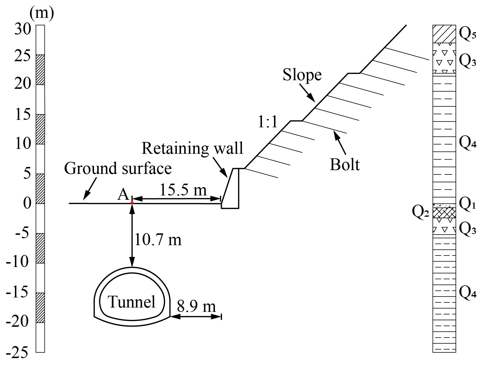
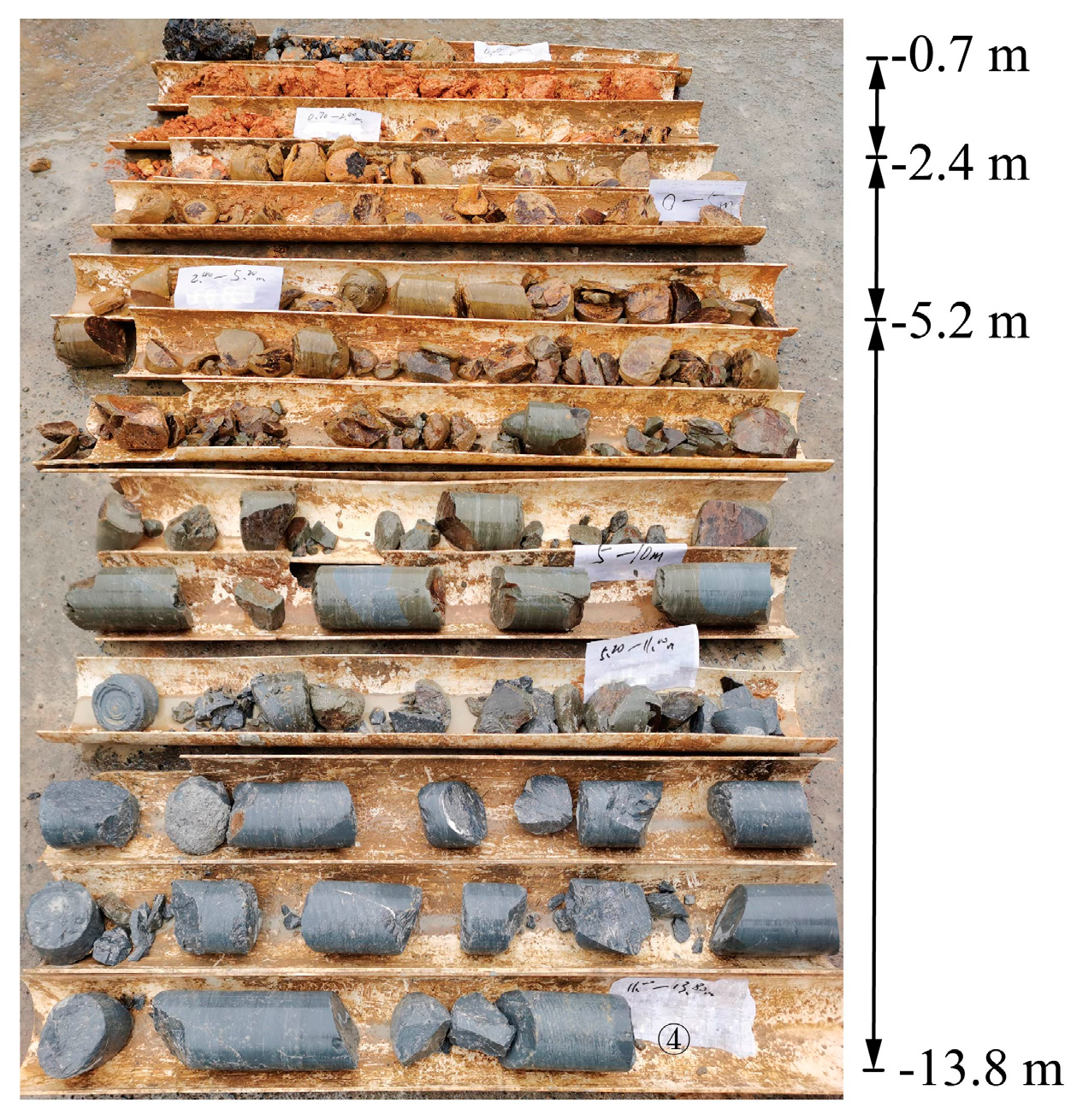
The shallow-buried section of the Xiaoheshan Tunnel of Hangzhou Metro Line 3 passes through the moderately weathered calcareous mudstone. As shown in Figure 1, on the right side of this tunnel, the length and height of the hillside parallel to the tunnel are 60 m and 30 m, respectively, and its slope rate is 1:1. By drilling at position A, the information of overlying rock and soil layer of the tunnel is obtained. From top to bottom, this tunnel’s weathered rock soil layer is subgrade filling, completely weathered mudstone, intensely weathered mudstone, and moderately weathered calcareous mudstone, respectively. The core samples drilled in the field are shown in Figure 2. The information on the soil layer above the surface is obtained according to the geological survey report. The lithology, distribution thickness, and representative symbols of each stratum are listed in Table 1.
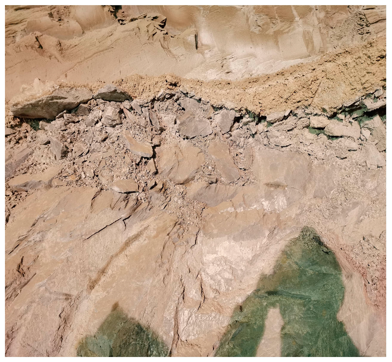
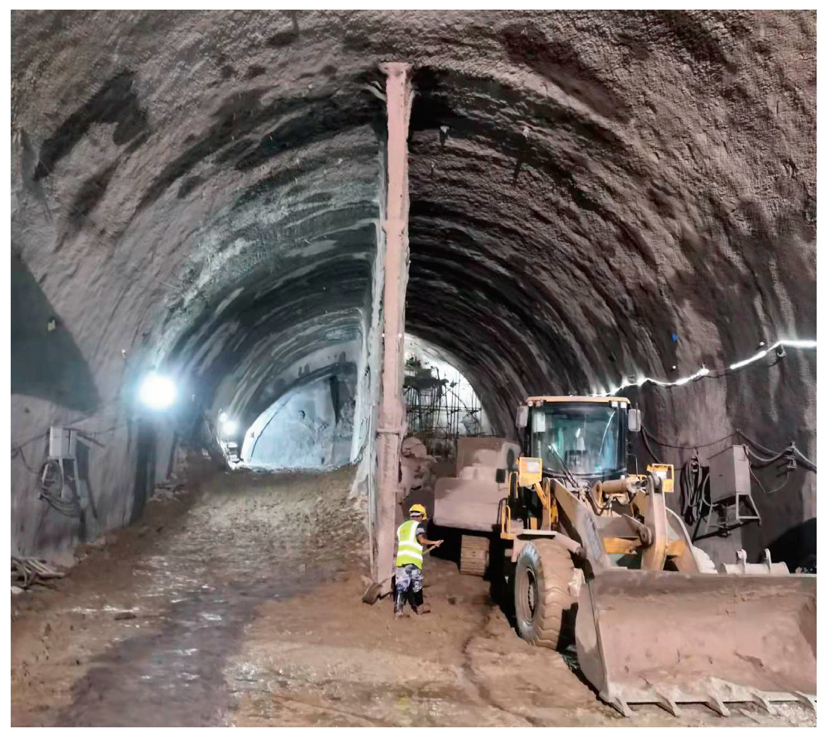
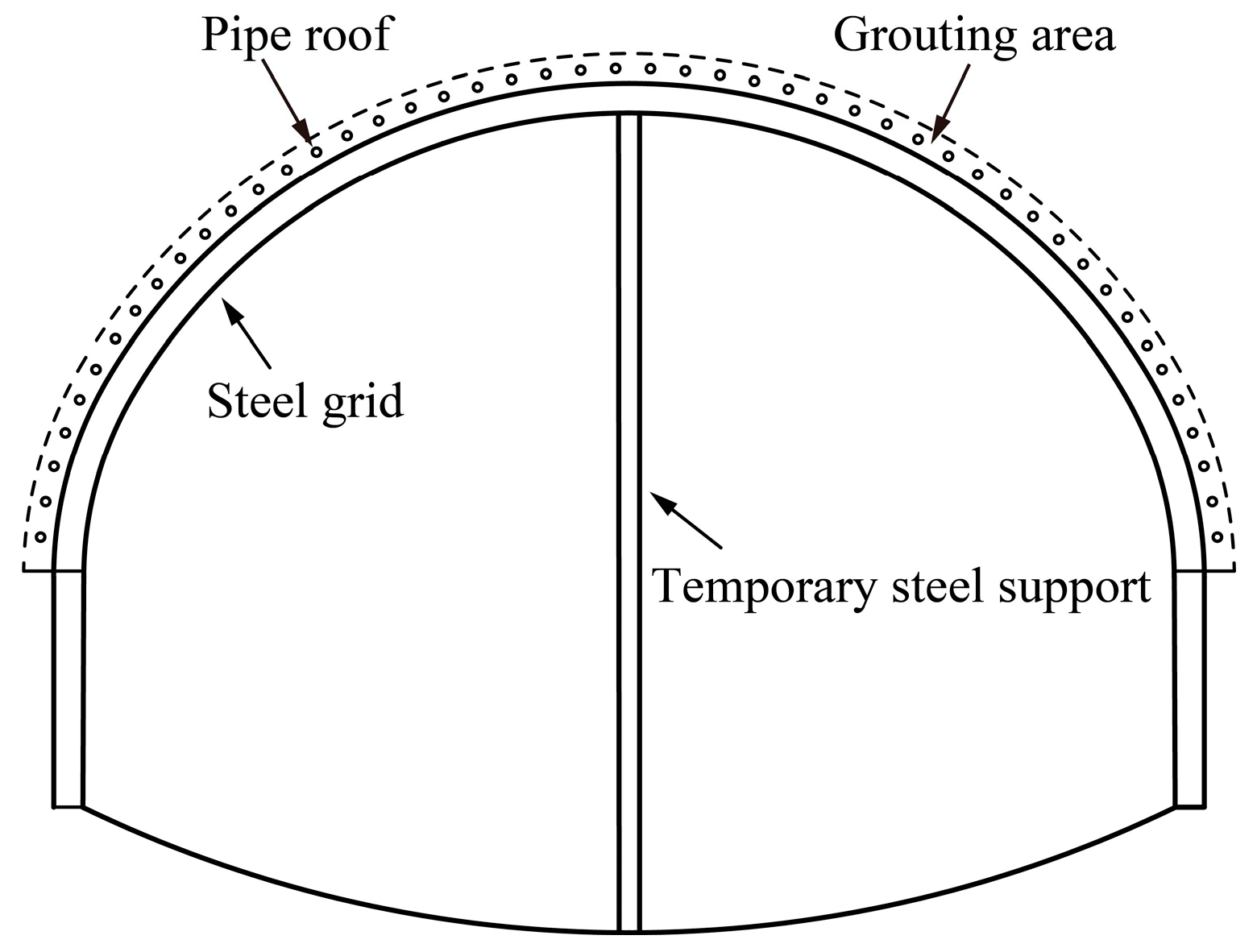
The range of the tunnel crown is strongly weathered mudstone. As shown in Figure 3, the joints, and fissures of rock mass in the local section are dense, and the self-stability is poor. During the excavation, the rock is easy to spall and even has the risk of local collapse. To ensure excavation safety, pipe roof pre-grouting is used to reinforce the surrounding rock of the crown, and the steel grid is laid around the tunnel in time. Then, the crown is supported by the vertical wall formed by multiple I-steel longitudinal connections, as shown in Figure 4.
2.2. Excavation Method of Shallow-Buried Large-Section Tunnel
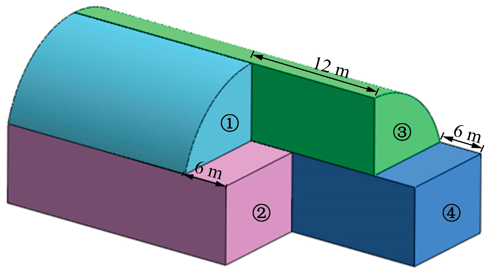
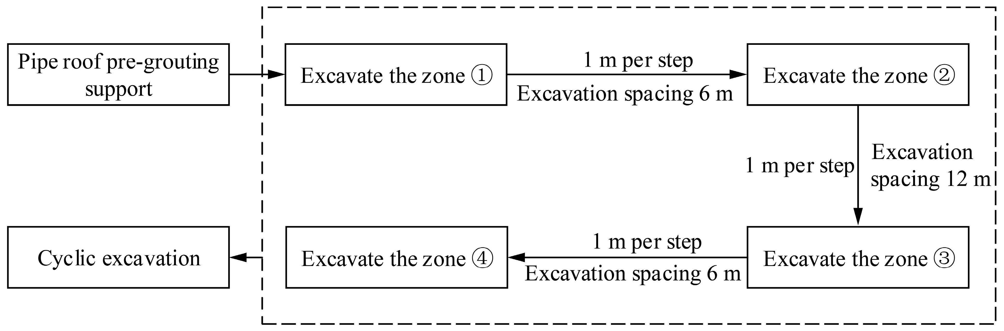
The buried depth of the Xiaoheshan Tunnel is 10.7 m, the tunnel section excavation height is 10 m, the maximum width is 13 m and the cross-section area is about 102.6 m2. Due to the coupling effect of rock mass fragmentation and lateral pressure of unilateral hillside, the surrounding rock self-stability of this large cross-section tunnel is poor, and the supporting structure is at risk of migration. During the construction, the pipe roof pre-grouting is gradually used to reinforce the surrounding rock with the advancement of the tunnel face. The excavation process of the two-step CDM is shown in Figure 5.
The specific technical processes are as follows:
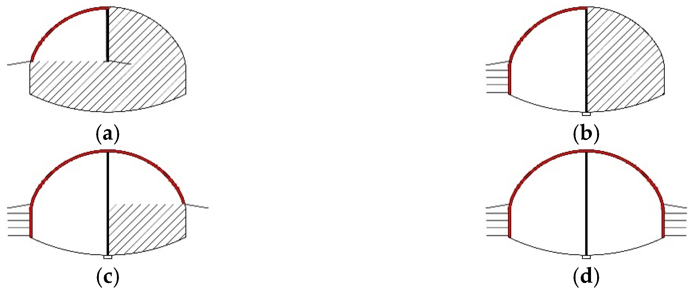
Step 1: The left upper bench is excavated (for 1 m per step), while at the same time, the steel grid, temporary steel supports, and feet-lock bolt are installed (see Figure 6a).
Step 2: The left lower bench is excavated (for 1 m per step), while at the same time, the steel grid, anchors, and temporary steel supports are installed (see Figure 6b).
Step 3: The right upper bench is excavated (for 1 m per step), while at the same time, the steel grid and feet-lock bolt are installed (see Figure 6c).
Step 4: The right lower bench is excavated (for 1 m per step), while at the same time, the steel grid and anchors are installed (see Figure 6d).
According to the sequence and excavation space shown in Figure 5, cyclic excavation is carried out step by step.
There are four anchors on the tunnel side wall, with a length of 4 m and longitudinal spacing of 1 m. The properties of the anchors are shown in Table 2. The surrounding rock support adopts C25 concrete; its shotcrete thickness is 18 cm. The temporary steel support adopts No.18 I-steel, whose elastic modulus is 210 GPa and the cross-section moment of inertia is 1659.45 cm4. The steel grid is made of Φ25 mm main reinforcement and Φ14 mm connecting reinforcement. Its elastic modulus is 210 GPa and the cross-section moment of inertia is 3686.76 cm4.
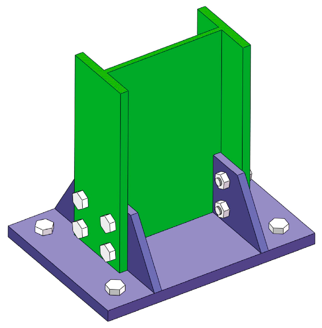
The temporary steel support of the large-section tunnel is a slender structure. Considering that instability may easily occur during the tunnel excavation process, a special steel plate structure bearing is used at the bottom to ensure its stability, and the bearing is fixed with bolts. Figure 7 shows the fixing mode of the lower end of the temporary steel support.
3. Mechanical Analysis of Supporting Structure
The Xiaoheshan Tunnel of Hangzhou Metro Line 3 is in the upper-soft and lower-hard strata, and the geological conditions are complex. Three kinds of support technologies are adopted in the process of tunnel excavation.
3.1. Pipe Roof
Pipe roof support is a common technology for the advanced pre-support of large-section tunnels. The circumferential pipe roof pre-support is adopted in this tunnel, as shown in Figure 8. Hollow bolts are used for the pre-support of the pipe roof, and there are several holes in the wall of the bolt for grouting. The material parameters of a single steel pipe are listed in Table 3. Figure 9 shows the schematic diagram of the grouting reinforcement of the pipe roof. r refers to the slurry diffusion radius of a single grouting steel pipe, and r is 0.5 m.
As the main structural form of tunnel pre-support, the pipe roof is used for bending resistance. The elastic modulus and weight of a single grouting steel pipe are equivalently converted according to Equations (1) and (2), respectively [32].
where,
| Eg | is the equivalent elastic modulus of the grouting steel pipe, |
| γg | is the equivalent weight of the grouting steel pipe, |
| E1 | is the elastic modulus of the steel pipe, E1 = 210 GPa, |
| I1 | is the moment of inertia of the steel pipe section, I1 = 1.77 × 10⁻⁶ m4, |
| γ1 | is the weight of the steel pipe, γ1 = 78.5 kN/m3, |
| A1 | is the cross-sectional area of the steel pipe, A1 =1.31 × 10⁻³ m2, |
| E2 | is the elastic modulus of the cement mortar, E2 = 2.8 × 10⁴ MPa, |
| I2 | is the moment of inertia of the filling cement mortar section, I2 = 4.91 × 10⁻⁶ m4, |
| γ2 | is the weight of the cement mortar, γ2 = 20.0 kN/m3, |
| A2 | is the cross-sectional area of the filling cement mortar, A2 = 7.85 × 10⁻³ m2. |
According to the principle of equivalence [33], the physical–mechanical parameters of the grouting reinforcement area are obtained by Equation (3). The relevant parameters are listed in Table 4.
where,
| E | is the elastic modulus of the grouting reinforcement area, |
| E0 | is the elastic modulus of the stratum, E0 = 59.4 MPa, |
| Sg | is the cross-sectional area of the grouting steel pipe, Sg = A1 + A2 = 9.16 × 10⁻³ m2, |
| Sc | is the cross-sectional area of the support section, Sc = l × 2r = 0.4 m2. |
3.2. Steel Grid Support
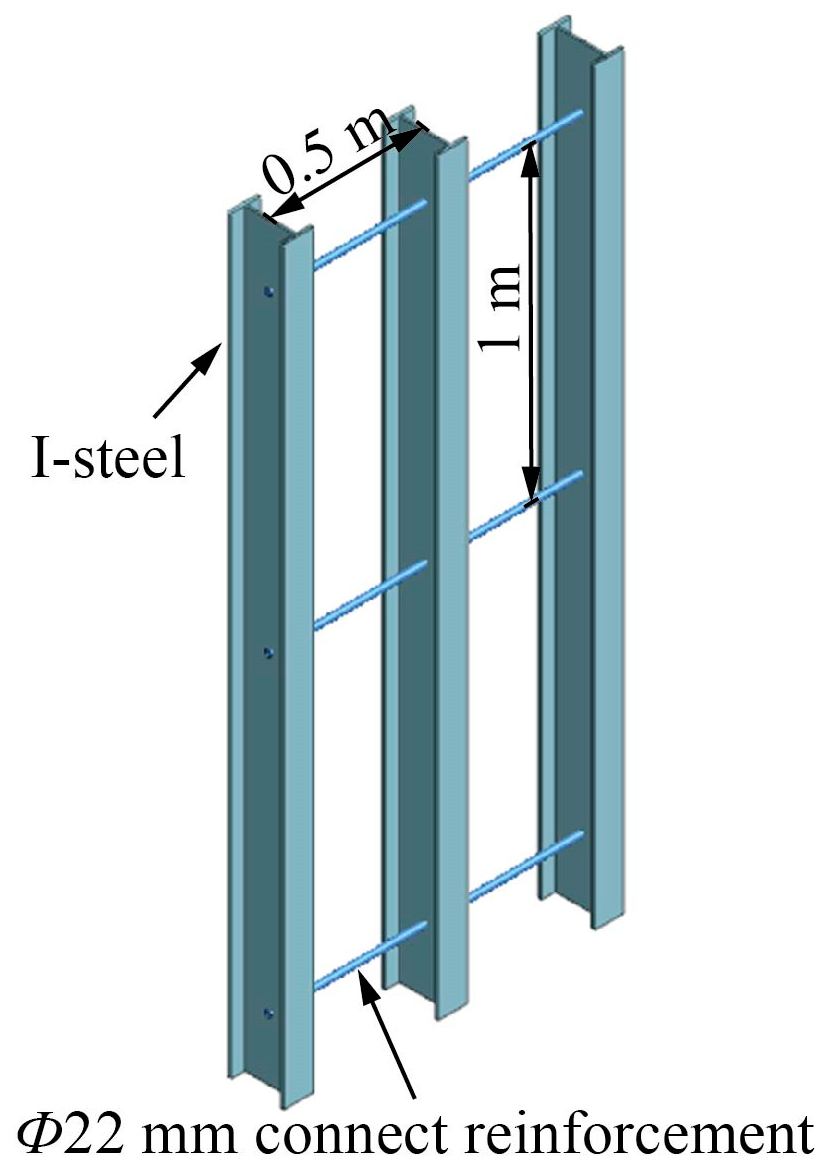
This tunnel is in the shallow-buried eccentric loose strata, and the self-stability of the surrounding rock is poor. Generally, the steel grid support is utilized to prevent the overlying rock from excessive deformation or even local collapse. Figure 10a shows the structural diagram of the steel grid, which is made up of four main reinforcements connected by connecting reinforcements. The detailed geometric and physical–mechanical parameters are listed in Table 5. Figure 10b shows the longitudinal arrangement of the steel grid along the tunnel, and its mechanical calculation diagram is shown in Figure 11.
The steel grid is the main bearing structure to restrain the early deformation of the surrounding rock [34,35], and it produces support resistance to the surrounding rock after deformation. The steel grid is regarded as an ideal elastic–plastic body, and the relationship between the displacement and the support resistance in the elastic deformation stage is obtained by Equation (4).
where,
| P | is the structural support resistance, |
| K | is the supporting stiffness of the structure, |
| u | is the radial displacement of the structure. |
According to the relevant literature [36], the formula for calculating the supporting stiffness when the supporting structure is a rectangular section is obtained as follows:
where,
| E | is the equivalent elastic modulus of the steel grid, |
| t | is the structural thickness of the steel grid, |
| v | is the Poisson’s ratio of the steel grid, |
| R | is the equivalent radius of the tunnel. |
The maximum support resistance Pmax of the steel grid can be obtained from Equation (6). Through the equivalence principle, the section form of the steel grid is equivalent to a rectangular section as shown in Figure 12. The yield strength and elastic modulus of the equivalent section form are calculated according to Equations (7) and (8), respectively.
where,
| σc | is the equivalent yield stress of the steel grid, |
| σs | is the yield strength of the steel grid, |
| Es | is the elastic modulus of the steel grid, |
| As | is the cross-sectional area of the steel grid, |
| A | is the equivalent rectangular cross-sectional area, |
| Is | is the moment of inertia of the section, |
| I | is the moment of inertia of the equivalent rectangular section. |
3.3. Temporary Steel Support
The large-section tunnel is excavated by the CDM, and the I-steel is used as a temporary support during the excavation process. The temporary steel support in this tunnel is made of No.18 I-steel longitudinally connected, and the space is consistent with the steel grid. Figure 13 shows the longitudinal connection method of the I-steel, and its geometric and physical–mechanical parameters are listed in Table 6.
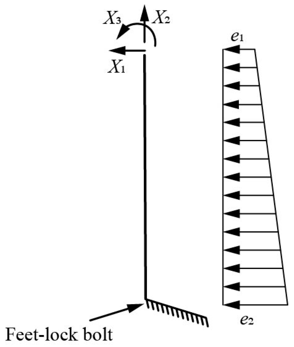
The steel support acts as a temporary support structure for tunnel excavation. Its top relates to the steel grid to bear the vertical surrounding rock pressure, while the right side is subjected to the lateral earth pressure on the unexcavated side. Figure 14 shows the mechanical calculation diagram of the temporary steel support.
4. Numerical Analysis
4.1. Model Building
MIDAS GTS NX finite element software is adopted to simulate the excavation process of this tunnel by two-step CDM. Calculation range: X × Y × Z = 90 m × 60 m × 50 m, as shown in Figure 15.
Boundary condition: The horizontal displacement constraints are imposed on the front, rear, left, and right boundaries of the model. The vertical displacement constraint is imposed on the bottom boundary. The surface is a free boundary.
Grid division: The strata, retaining wall, and grouting reinforcement area are simulated by the hexahedral solid element, with a number of elements of 161,769 and nodes of 143,226. The pipe roof, temporary steel support, and connection reinforcements are simulated by the beam element, with the number of elements of 5680 and nodes of 5819. The steel grid, tunnel sidewall, and concrete shotcrete layer are simulated by the plate element, with a number of elements of 4569 and nodes of 5158. The anchor adopts the embedded truss element, with several elements of 2898 and nodes of 3556. The total number of elements is 174,916, and the number of nodes is 157,759.
4.2. Fundamental Assumption
Given the location of the underground tunnel section, the stratum is composed of subgrade filling, completely weathered mudstone, intensely weathered mudstone, and moderately weathered calcareous mudstone from top to bottom. The numerical simulation of the tunnel excavation conforms to the following assumptions:
- (1)
- Each geological layer, pipe roof grouting and solid are regarded as homogeneous and isotropic media.
- (2)
- The deformation and failure of the tunnel surrounding rock, temporary steel support, and pipe roof grouting conform to the classical elastic–plastic theory.
- (3)
- Without considering the influence of disturbance caused by tunnel excavation on the structure itself and the effect of tectonic stress, only considering the influence of self-weight on the structure itself. The initial horizontal stress is calculated by using the surrounding rock gravity in MIDAS software, which can be expressed by Equation (9).
| σh | is the horizontal stress, |
| σv | is the vertical stress, |
| μ | is Poisson’s ratio. |
4.3. Constitutive Relation
The constitutive relationship between I-steel and steel bars using the BKIN model and Von-Mises criterion is shown in Equation (10).
where,
| σ1 | is the first principal stress of the material, |
| σ2 | is the second principal stress of the material, |
| σ3 | is the third principal stress of the material, |
| σs | is the yield point of the material, and σs = 235 MPa, |
| K | is the shear yield strength of the material. |
The Mohr–Coulomb elastic–plastic failure strength criterion is adopted to characterize the constitutive relationship of the tunnel surrounding rock and pipe roof grouting. The plastic failure judgment is based on Equation (11).
where,
| τ | is the shear stress on the shear plane, Pa, |
| σ | is the normal stress on the shear plane, |
| φ | is the internal friction angle, |
| σ1 | is the first principal stress, |
| σ3 | is the third principal stress. |
4.4. Calculated Parameters
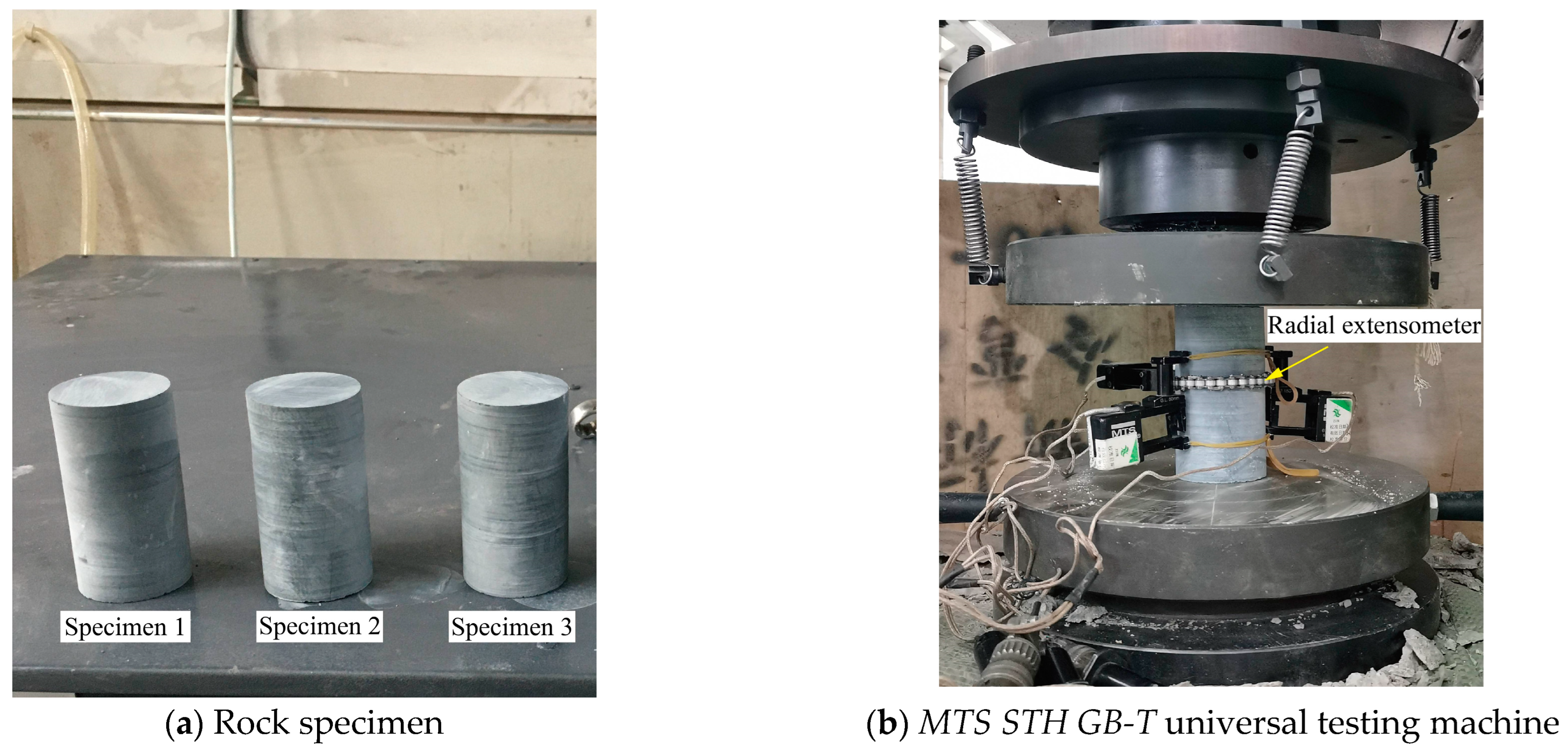
To obtain the physical–mechanical parameters of rock and soil accurately, the rock core is drilled in the engineering site and processed into standard rock samples, as shown in Figure 16a. Figure 16b shows the MTS STH GB-T universal testing machine, which is adopted to carry out the uniaxial compression test of rock based on relevant standards [37]. The uniaxial compressive strength, elastic modulus, Poisson’s ratio, and other physical–mechanical parameters of moderately weathered calcareous mudstone are listed in Table 7.
The physical and mechanical parameters of other rock and soil layers are comprehensively considered according to the data provided by the geological survey report and combined with the classification standard of engineering rock mass [38]. At the same time, according to Part 3 (Mechanical analysis of supporting structure), the calculation parameters of the relevant supporting structures are determined, which are listed in Table 8.
4.5. Analysis Process
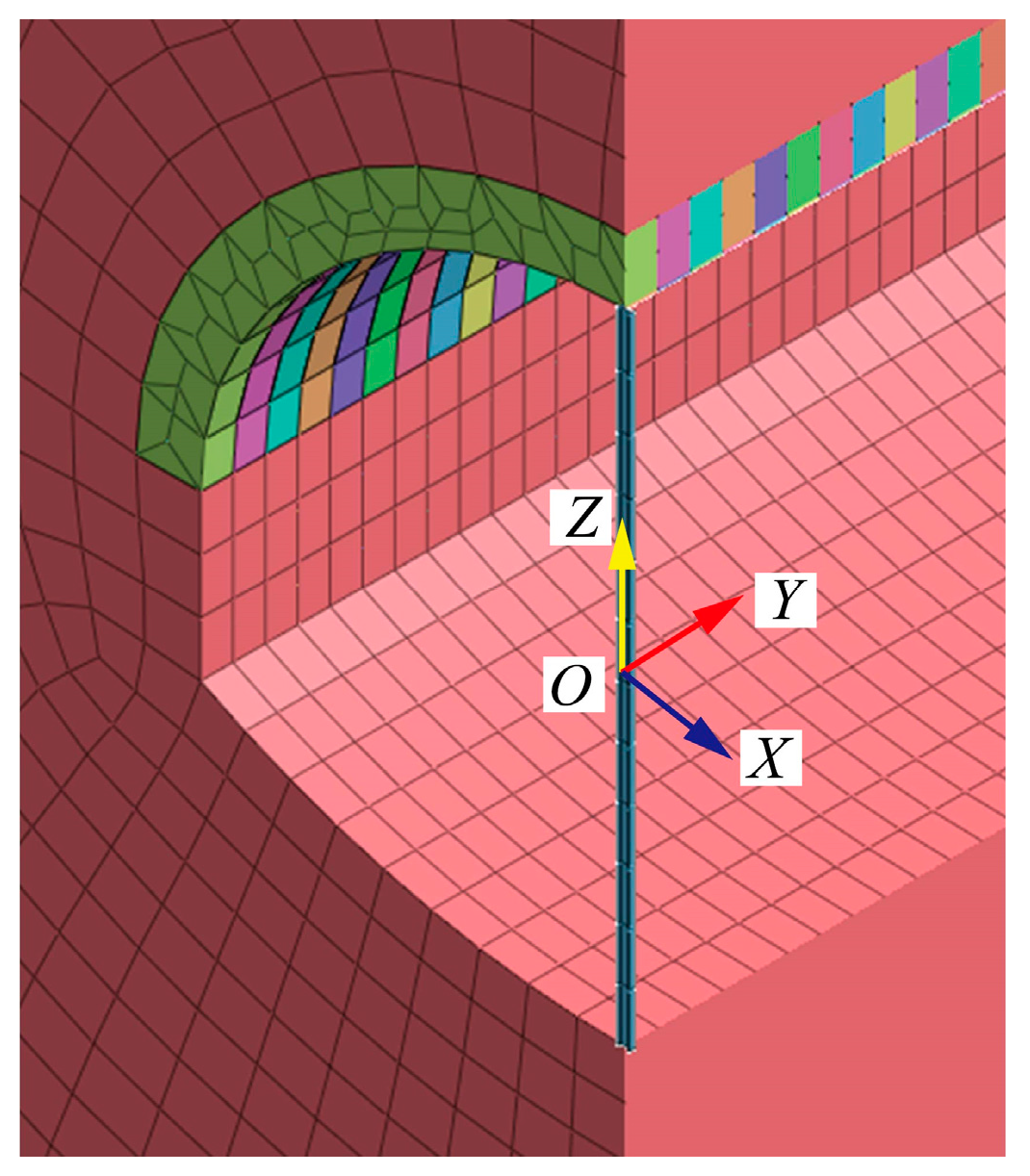
Based on the field construction steps of Xiaoheshan Tunnel; the pre-grouting reinforcement area of the pipe roof; the excavation sequence of the bench method; and the support process of the temporary steel support in the process of tunnel excavation are simulated. The simulation process of three-dimensional excavation and support is shown in Figure 17. A schematic diagram of the coordinate is shown in Figure 18.
The excavation is conducted cyclically according to the method shown in Figure 19. During the excavation process, the steel grid, temporary steel support, and feet-lock bolt at the corresponding positions are installed in time.
During the process of numerical simulation, the three-dimensional models of tunnel excavation are established to analyze the effect of temporary steel support. The effect of the temporary steel support on the surrounding rock pressure and displacement during tunnel excavation is studied, and its stress and deformation are analyzed.
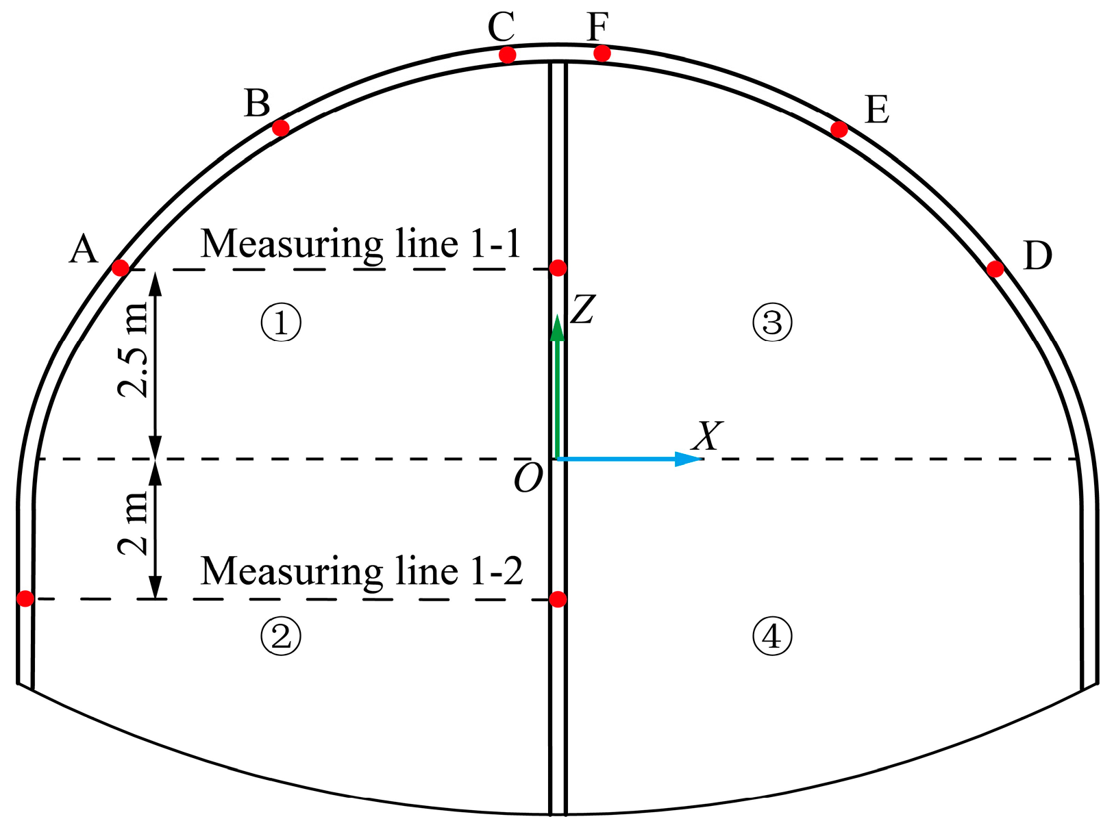
We set up six measuring points (A, B, C, D, E, and F) to monitor the settlement of the crown and spandrel and two horizontal measuring lines (1-1 and 1-2) to analyze the horizontal displacement of the temporary steel support. The layout of the measuring points is shown in Figure 20. The analysis results are as follows.
4.5.1. Surrounding Rock Stress
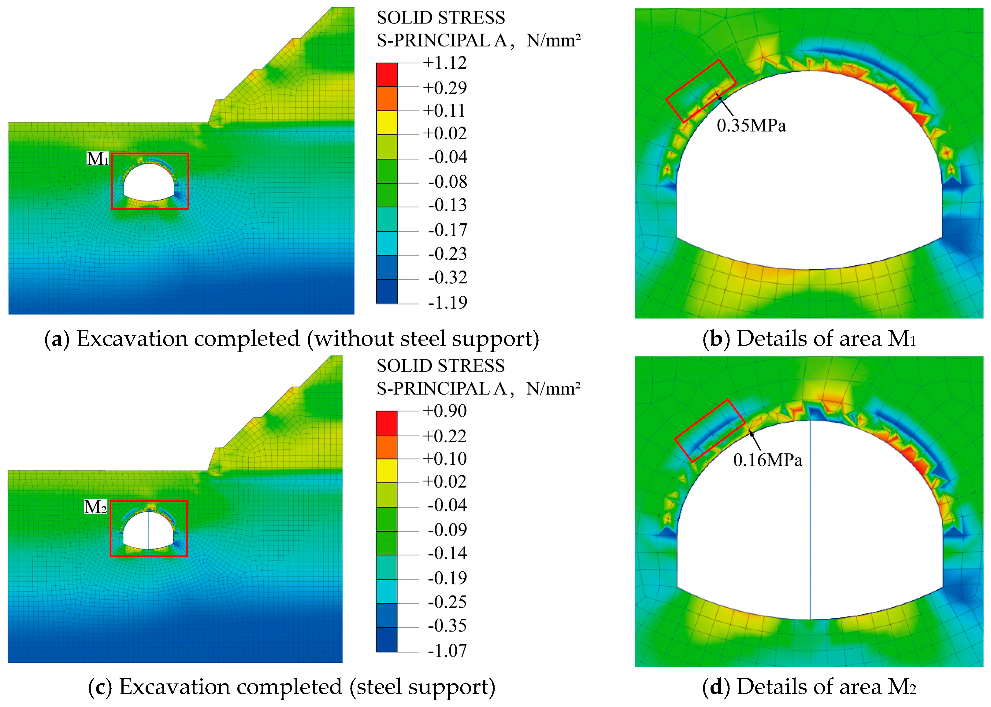
During the excavation process, the failure of the surrounding rock is related to the maximum principal stress of the surrounding rock. Therefore, this paper analyzes the maximum principal stress of the surrounding rock in the grouting area of the pipe roof and other parts. Figure 21 shows the stress distribution of the surrounding rock during excavation.
As is shown in Figure 21: (1) In the process of tunnel excavation with and without a temporary steel support, the distribution of the first principal stress of the surrounding rock is consistent. After all the excavation is completed, the maximum tensile stress changes from 1.12 MPa to 0.90 MPa, and the maximum compressive stress changes from −1.19 MPa to −1.07 MPa. The changes are not obvious. The temporary steel support has a negligible effect on the extreme value of the first principal stress of the surrounding rock. (2) Affected by the unsymmetrical loading, the stress state around the tunnel is complex, and the maximum tensile stress occurs near the spandrel and bottom of the tunnel. The temporary steel support is beneficial to improve the stress state of the surrounding rock of the tunnel, especially the surrounding rock stress at the left spandrel and bottom of the tunnel. (3) Comparing Figure 21b,d, after the temporary steel support is installed, the maximum tensile stress on the left spandrel decreased from 0.35 MPa to 0.16 MPa, which decreased by 54.3%. At the same time, the range of tensile stress decreases, and the stress state in some areas is changed from tension to compression, which is conducive to the stability of the surrounding rock. The existence of temporary steel support makes the stress distribution of the surrounding rock on the left spandrel more reasonable. (4) During the tunnel excavation process, the surrounding rock at both ends of the temporary steel support produces a large stress concentration, which is prone to local damage. Attention should be paid to the flexible support design of the temporary steel support.
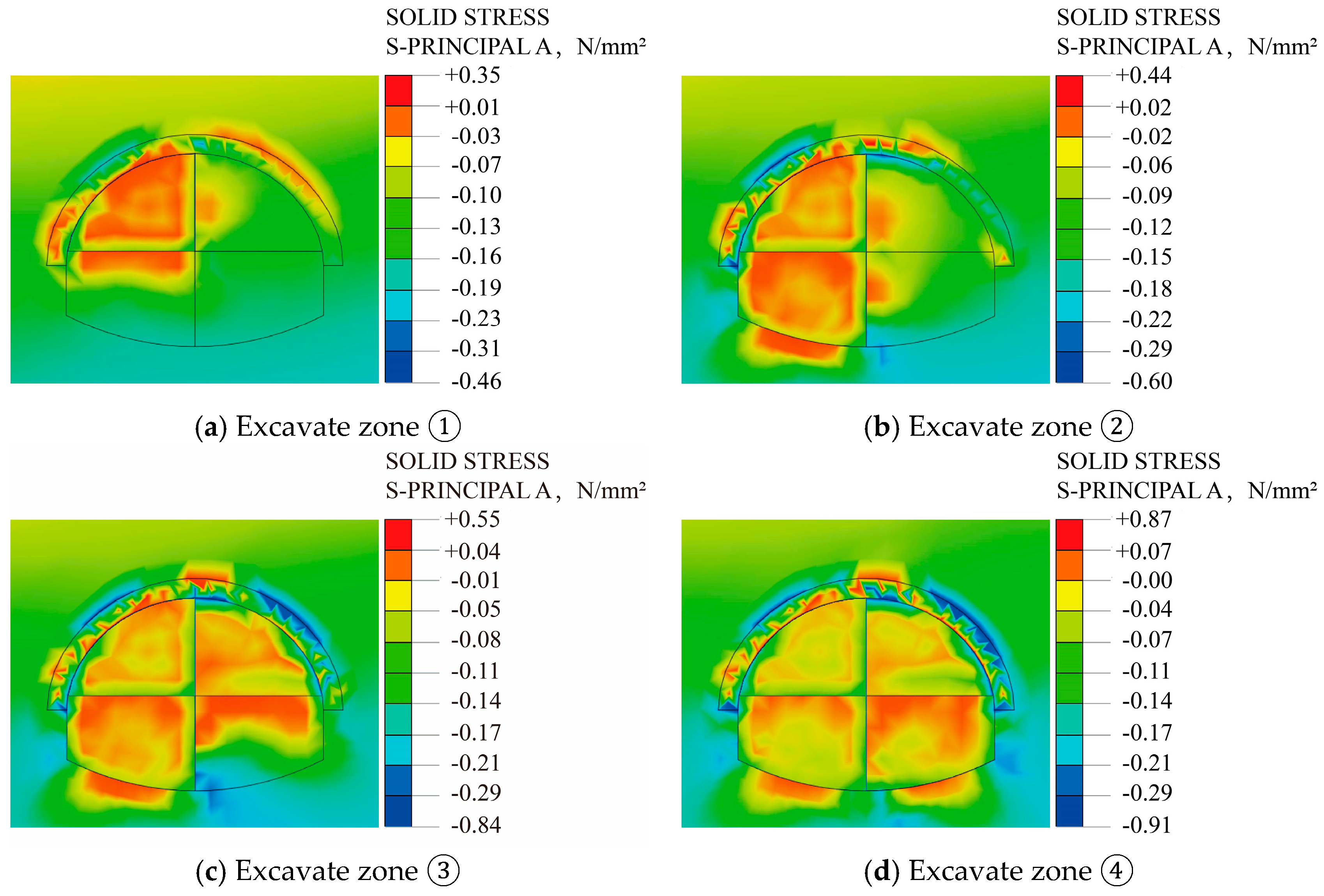
From the above analysis, the existence of the temporary steel support greatly improves the distribution range of the surrounding rock. Now, we further discuss the stress change around the tunnel in the process of a two-step CDM excavation under a temporary steel support. The local stress map is shown in Figure 22.
As is shown in Figure 22: (1) When the two-step CDM was adopted to excavate the tunnel, the stress change of the surrounding rock of the tunnel presents the characteristics of stages and the stress release sequence changes with different excavation sequences. (2) When excavating the left upper bench (Figure 22a), due to the influence of the eccentric pressure, compressive stress occurs in the left spandrel, and the range of compressive stress distribution is small. When excavating the left lower bench (Figure 22b), the compressive stress of the left spandrel increases, and the tensile stress is generated at the bottom of the tunnel. When excavating the right upper bench (Figure 22c), due to the influence of the right bias, the magnitude and distribution range of the compressive stress on the right spandrel are larger than those in the tunnel excavation of the left upper bench and the left lower bench. When excavating the right lower bench (Figure 22d), the magnitude and distribution of the compressive stress on the right spandrel increased, but the change range was small. The excavation of the right lower bench has little effect on the stress on the right spandrel. (3) The excavation of the upper bench has a greater impact on the stress of the spandrels on both sides of the tunnel, and the excavation of the lower bench has a greater impact on the stress at the bottom of the tunnel.
4.5.2. Displacement of Surrounding Rock
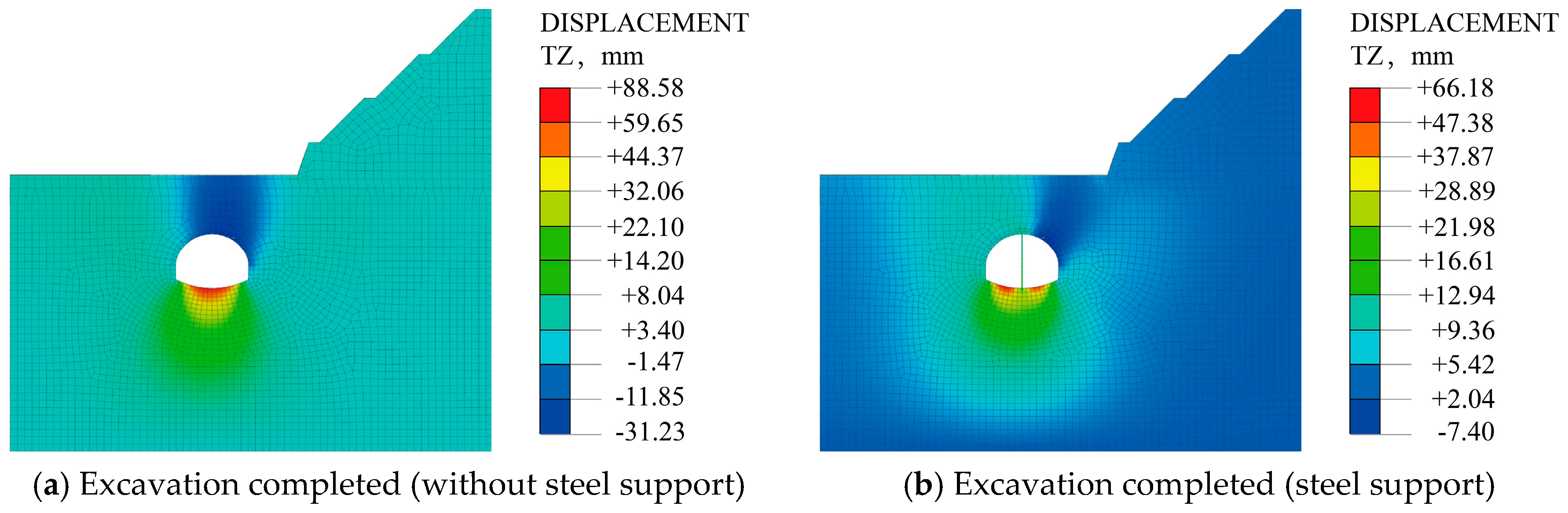
The distribution of the surrounding rock settlements is shown in Figure 23.
As is shown in Figure 23: (1) During the excavation process of tunnels with and without temporary support, the settlement distribution of the surrounding rock shows consistently. Affected by the bias, the settlement of the surrounding rock is mainly distributed near the right spandrel. (2) The existence of the temporary steel support greatly reduces the settlement of the surrounding rock and the bottom uplift of the tunnel and improves the distribution range of the settlement of the surrounding rock, especially the settlement of the left spandrel. The maximum settlement of surrounding rock changes from −31.23 mm to −7.40 mm, which is reduced by 76.3%. The bottom uplift changes from 88.58 mm to 66.18 mm, which is reduced by 25.3%. (3) After the temporary steel support is installed, the uplift at the bottom of the tunnel is reduced due to the reaction force of the support. The temporary steel support bears a large vertical surrounding rock pressure, and attention should be paid to its flexible support design during construction.
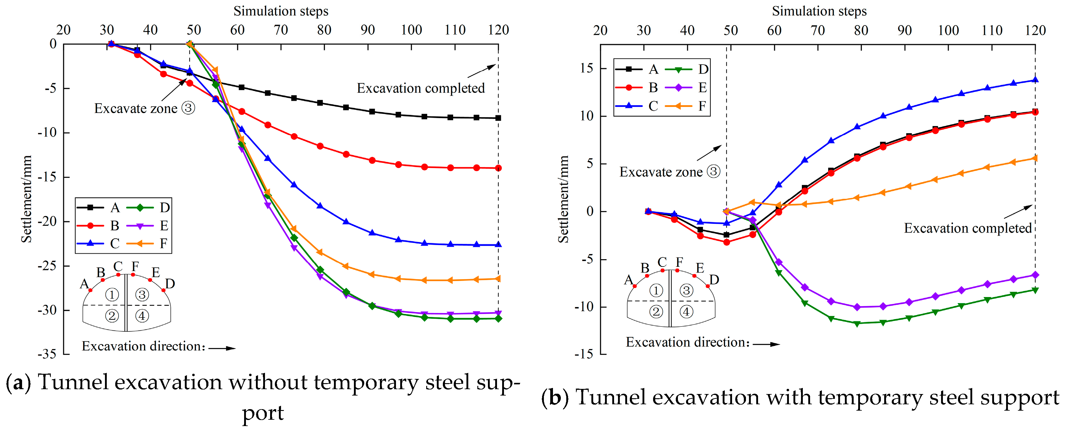
In order to eliminate the impact of boundary effects on the monitoring section, the typical section should be far enough from the start boundary of the tunnel, generally two to three times the tunnel diameter. Considering that the maximum span of this model tunnel is 13 m, the section y = 30 m is taken as the typical section. Figure 24 shows the change curve of the settlement during the tunnel excavation process.
As is shown in Figure 24: (1) During the simulation process of tunnel excavation with and without temporary steel support, the settlement values of points D and E are both greater than the settlement values of points A and B. After all the excavation is completed, affected by the bias pressure and the excavation sequence, the maximum settlement value is distributed in the right spandrel. When excavating the right upper bench ③, a high-strength steel grid should be installed, and spray concrete in time. (2) Comparing Figure 24a,b, the maximum displacement of point A changes from −8.3 mm to 10.9 mm, and the maximum displacement of point B changes from −13.9 mm to 10.9 mm. At the same time, it can be seen from Figure 24b that the existence of the temporary steel support causes the local uplift of the left spandrel, and with the advance of excavation, the number of steel supports increases, and the uplift value of the left spandrel increases gradually, which decreases the surrounding rock settlement of the left spandrel greatly. (3) The displacement increasing rate of each monitoring point in the early excavation is relatively obvious, and the displacement change rate gradually became stable before the excavation was completed.
4.5.3. Analysis of Mechanical Characteristics in Temporary Steel Support
From the above analysis, in the process of tunnel excavation by two-step CDM, due to the existence of temporary steel support, the settlement of surrounding rock and the uplift of the tunnel bottom are greatly reduced, and the principal stress distribution of the left spandrel tends to be more uniform. The temporary steel support is No. 18 I-steel. After the whole section of the I-steel is installed, the height is 10 m, the width is 8 cm, and the height–width ratio is 1:0.018. It is a slender structure, and it is easy to lose stability in the process of excavation. Now, the stability and deformation law of the steel support is analyzed as follows.
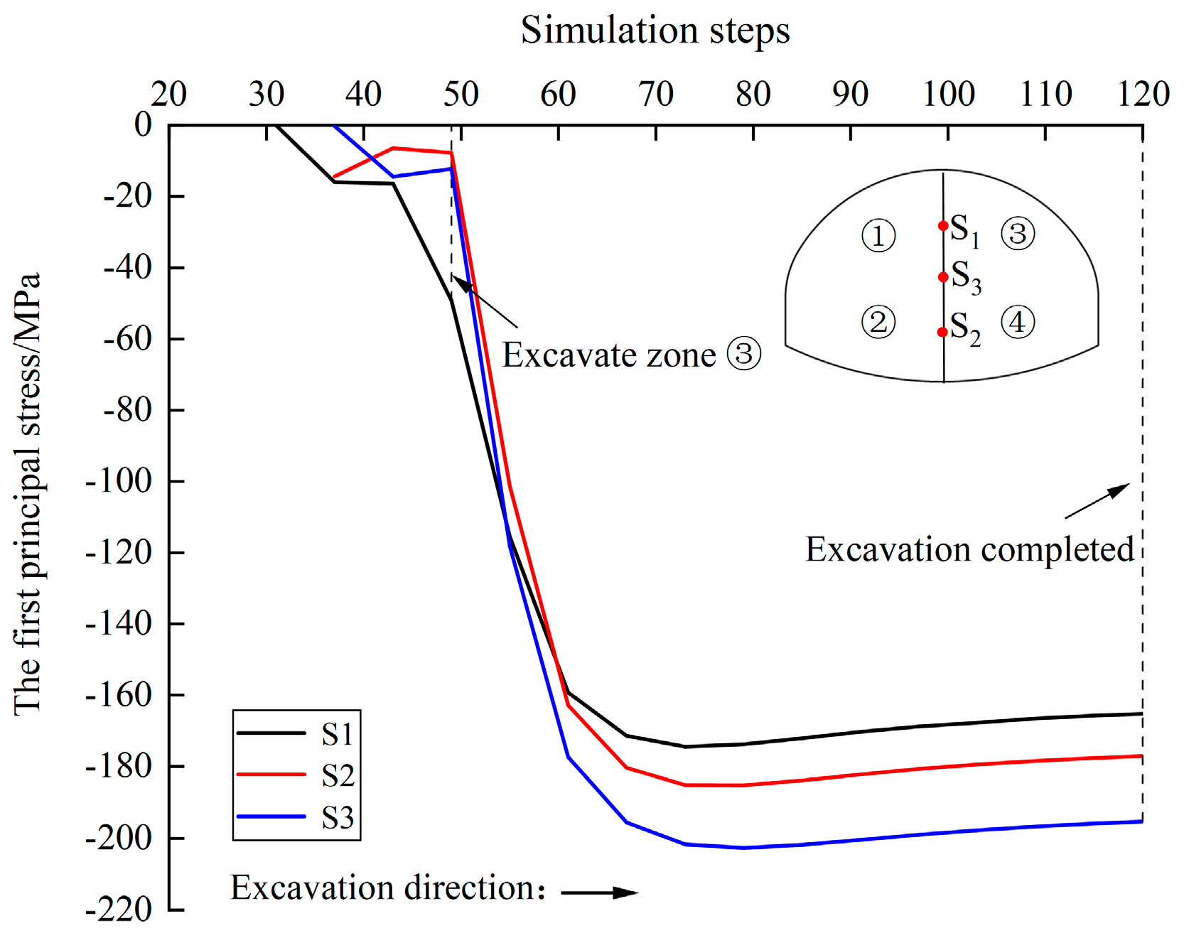
We set up three monitoring points (S1, S2, and S3) to analyze the principal stress of the temporary steel support. The measuring points S1 and S2 are located at the midpoint of the temporary steel support of the upper and lower bench, respectively. The measuring point S3 is located at the connection of the upper and lower bench. Through the MIDAS’ extraction function, the principal stress results of the temporary steel support are extracted. Figure 25 shows its principal stress change curve in cross-section y = 30 m.
It can be seen from Figure 25 that: (1) During the tunnel excavation process, there is an obvious “bench-type” phenomenon in the change of the first principal stress of the temporary steel support, which is caused by the excavation of the tunnel by two-step CDM. At the same time, the stress changes of the temporary steel support on the upper and lower bench are the same. (2) The stress increase rate of the temporary steel support during the excavation of the right upper bench ③ is significantly faster than that of other parts’ excavation. The reason is that with the excavation of the rock and soil of the right upper bench ③, the lateral earth pressure of the temporary steel support on the upper bench is completely released. It only bears the load of the upper surrounding rock, and the stress value increases. At the same time, the earth pressure on the right side of the temporary steel support of the lower bench is further released, and its stress value increases synchronously. (3) During the entire excavation process, due to the stress concentration at the joint of the upper and lower bench of temporary steel support, the stress value at the monitoring point S3 continued to increase, with a maximum value of −202.7 MPa, which did not reach the yield strength of the I-steel of 235 MPa in terms of value, so the structure is safe. To ensure the construction safety, attention should be paid to the reinforcement of the temporary steel support at the joint of the upper and lower bench, and the transverse steel support can be set up at the joint if necessary.
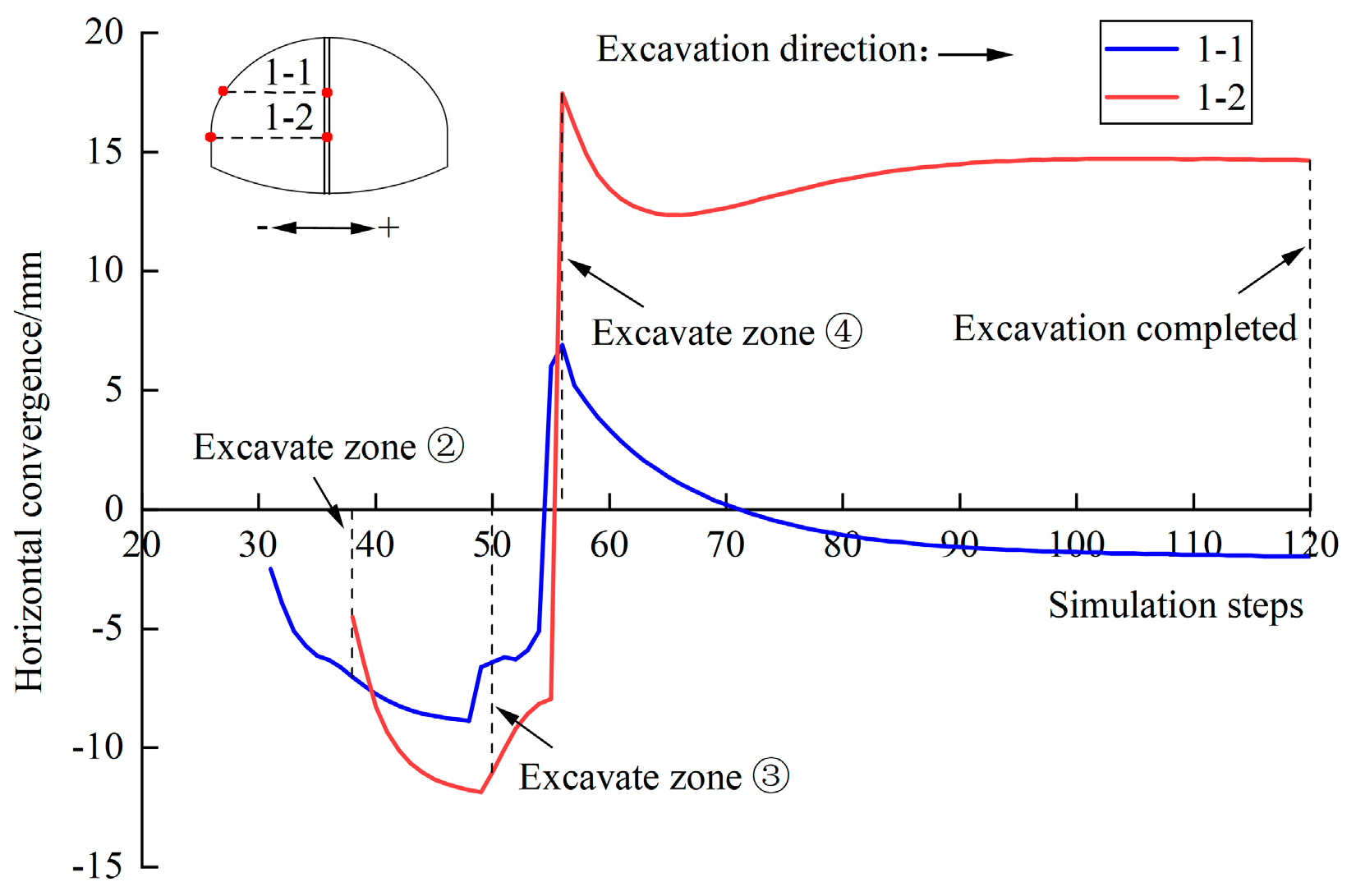
Through the MIDAS’ extraction function, the data of two horizontal convergence lines, 1-1 and 1-2, in cross-section y = 30 m are extracted. The convergence changes of the two-step CDM tunnel excavation process is shown in Figure 26.
It can be seen from Figure 26 that: (1) The change law of the relative horizontal convergence of the temporary steel support at the upper and lower bench is basically the same. The maximum convergence of the upper and lower bench steel support in the excavation process is −8.9 mm and −11.9 mm, respectively, and the maximum expansion is 6.9 mm and 17.5 mm, respectively. (2) After the excavation of the left upper bench ①, the horizontal convergence of the upper bench steel support (measuring line 1-1) increases rapidly to −6.6 mm. After the excavation of the left lower bench ②, the horizontal convergence gradually increases to −6.9 mm. At this time, the temporary steel support bears vertical surrounding rock pressure and lateral earth pressure. With the gradual advance of excavation, the pressure increases, increasing the horizontal convergence. At the same time, the horizontal convergence of the lower bench steel support (measuring line 1-2) increases rapidly to 11.0 mm. (3) After the excavation of the right upper bench ③, the relative horizontal displacement of the upper bench steel support changes from −6.4 mm to 6.9 mm, and the change range is 13.3 mm. The reason is that when the right upper bench ③ is excavated, the earth pressure on the right side of the upper bench steel support is released, and its relative horizontal displacement state changes from convergence to expansion gradually. At the same time, the relative horizontal displacement of the lower bench steel support changes from −11.0 mm to 17.5 mm, with a range of 28.5 mm. The reason is that due to the excavation of the right upper bench ③, the earth pressure on the right side of the lower bench steel support is further released, which leads to the decrease of its convergence value. (4) The convergence and expansion of the temporary steel support move to the left and right, respectively. The convergence of the temporary steel support is mainly caused by the excavation of the left upper bench ① and lower bench ②, and the expansion is mainly caused by the excavation of the right upper bench ③ and lower bench ④. The deformation of the upper bench steel support is mainly affected by the left upper bench ① and the right upper bench ③ excavation, and the deformation of the lower bench steel support is mainly affected by the right upper bench ③ and lower bench ④ excavation. (5) The deformation of the upper bench steel support undergoes four stages: convergence, expansion, convergence, and stability. The deformation of the lower bench steel support undergoes five stages: convergence, expansion, convergence, expansion, and stability.
The above analysis shows that when the right upper bench ③ is about to be excavated, the horizontal convergence of the upper and lower bench steel support reaches the maximum at the same time, and the deformation state of the temporary steel support in the 50th construction step is extracted, as shown in Figure 27. The maximum transverse deformation of the temporary steel support occurs at the joint of the upper and lower bench, which is 21.28 mm. To further ensure construction safety, attention should be paid to the reinforcement treatment at the joint of the upper and lower bench of the temporary steel support in the process of excavation, and transverse supports can be set up if necessary.
5. Field Monitoring
5.1. Measurement Method
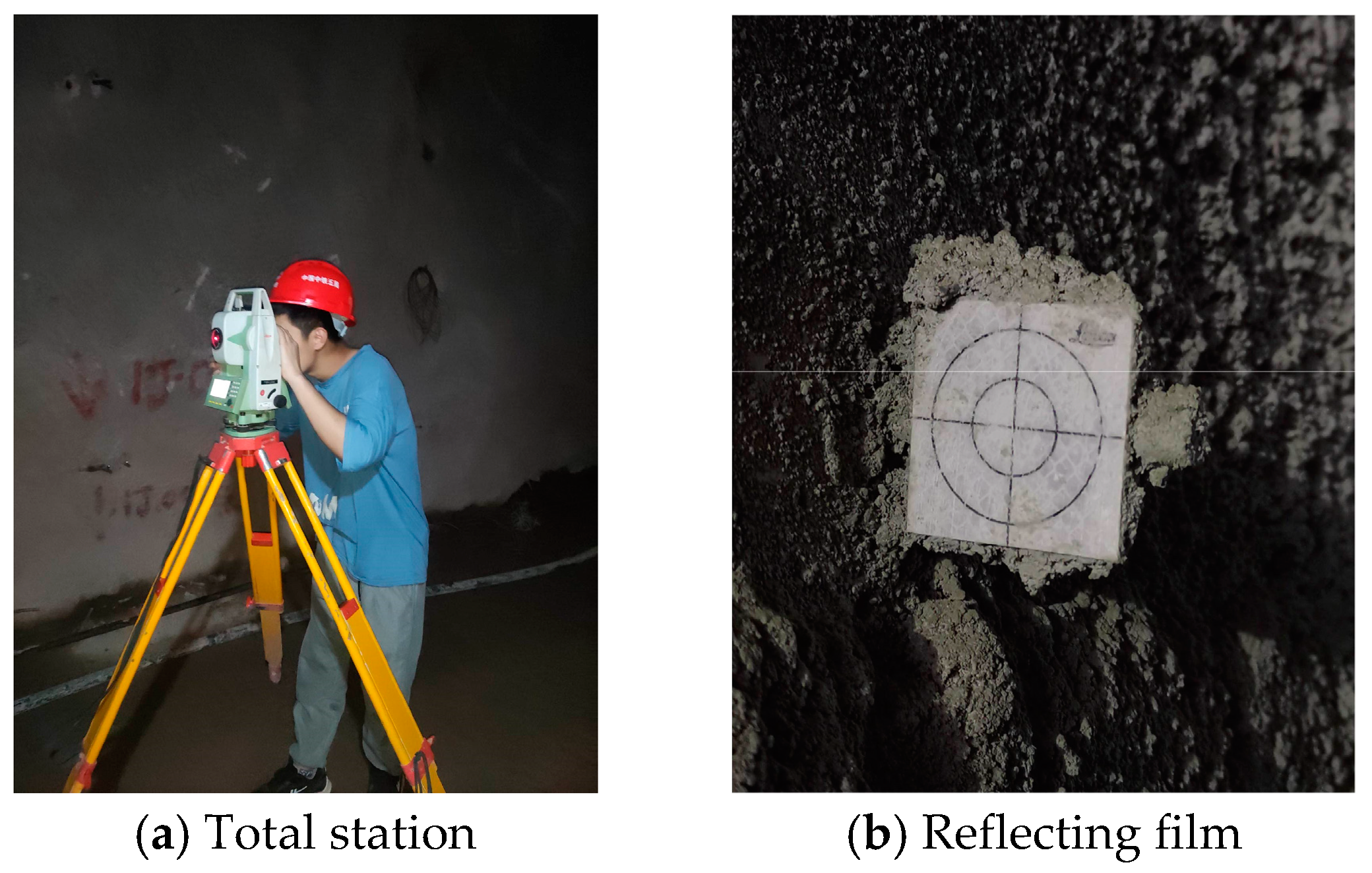
Based on the above theory and numerical analysis of the Xiaoheshan Tunnel of Hangzhou Metro Line 3, field tests were conducted. To analyze the deformation characteristics of the temporary steel support and surrounding rock, a field test was carried out. Then, the numerical simulation results were compared with field monitoring. Since the tunnel is excavated by the two-step CDM, the traditional measurement method (clearance extensometer) may not be able to monitor the early deformation of the tunnel due to the limitations of the excavation equipment and site conditions during the excavation process. Therefore, Leica-TS09plus total station and reflective film were adopted to monitor the spandrel settlement and horizontal convergence of the tunnel, as shown in Figure 28. The ranging accuracy is ± (2 mm + 2 ppm).
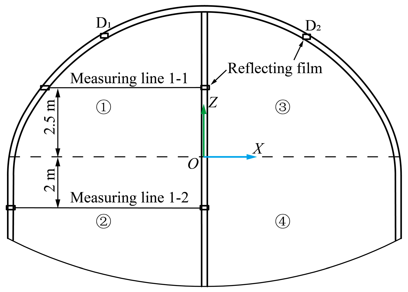
In this paper, the cross-section y = 30 m is selected for the field test. Figure 29 illustrates the layout of the measuring points. Two measuring lines, 1-1 and 1-2, are set to measure the horizontal convergence during tunnel excavation. In addition, two points (D1 and D2) are set to measure the spandrel settlement. The positions of the monitoring points in the field are consistent with those in the process of numerical simulation.
5.2. Analysis of Monitoring Results
5.2.1. Horizontal Convergence
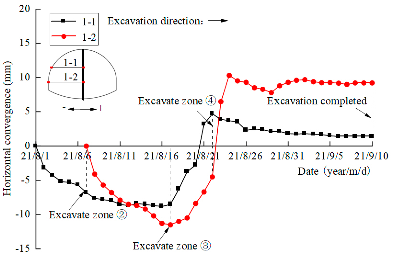
The convergence results are listed in Table 9, and the time curve of the horizontal convergence is shown in Figure 30.
As can be seen from Figure 30, on the measuring line 1-1, after the excavation of the left upper bench ①, the convergence value and growth rate increase and the convergence value increases to about −6.8 mm. After the excavation of the left lower bench ②, the convergence value continues to increase, while the growth rate turns down. The excavation of the left lower bench ② has little effect on the convergence of the temporary support of the upper bench. After the excavation of the right upper bench ③, due to the release of the earth pressure on the right side of the temporary support of the upper bench, the convergence value becomes smaller, and the deformation state gradually changes from convergence to expansion, and gradually tends to be stable after the excavation of the right lower bench ④.
On measuring line 1-2, after the excavation of the left lower bench ②, the convergence rate accelerates gradually, and the convergence value increases to about −11.5 mm. After the excavation of the right upper bench ③, the pressure on the right side of the temporary support of the lower step is released, the convergence value is smaller, and the deformation state is gradually transformed from convergence to expansion. After the excavation of the right lower bench ④, the lateral earth pressure is further released, and the deformation speed of the temporary support of the lower bench increases rapidly at first, then there are some slight rebounds and finally tends to be stable.
There are numerical errors between the numerical simulation and the field monitoring data, while the variation law is basically consistent. The deformation of the temporary steel support at the upper bench undergoes four stages: convergence, expansion, convergence, and stability. The deformation of the temporary steel support at the lower bench undergoes five stages: convergence, expansion, convergence, expansion, and stability.
5.2.2. Spandrel Settlement
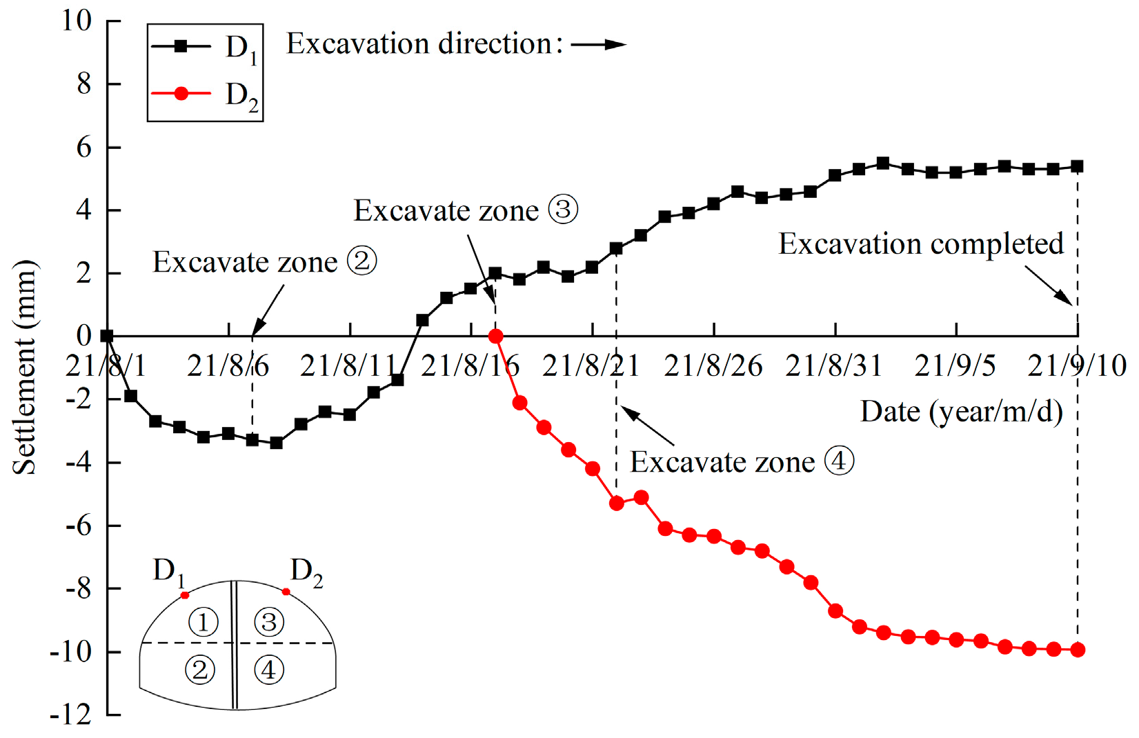
The spandrel settlement results are listed in Table 10, and the time curve of spandrel settlement is shown in Figure 31.
It can be seen from Figure 31: (1) In the initial stage of tunnel excavation, the settlement of the left spandrel increased slowly. With the advance of excavation, the number of temporary steel supports increased, and the displacement state of monitoring point D1 changed from settlement to uplift gradually, which indicated that the surrounding rock on the left spandrel was uplifted. Before the end of the excavation, the uplift value became stable gradually. (2) Affected by the slope bias, when excavating the right upper bench ③, the settlement of the right spandrel (measurement point D2) increased rapidly. When excavating the right lower bench ④, the settlement value of monitoring point D2 continued to increase, while the growth rate slowed down and stabilized before all the excavation was completed. (3) The settlement value obtained by numerical simulation was smaller than the measured value, while the variation law was the same. Considering that the geological strata in the actual tunnel are more complex than that in the numerical simulation, the difference in settlement value is acceptable, which verifies the correctness of the numerical simulation calculation.
6. Conclusions
Combined with the numerical simulation and field monitoring, the deformation and mechanical characteristics of temporary steel support during the process of unsymmetrical loading tunnel excavation are explored. The conclusions are as follows:
- (1)
- In the process of simulating tunnel excavation with or without temporary steel support, the stress distribution of the surrounding is basically the same. The existence of steel supports changes the maximum tensile stress of the left spandrel from 0.35 MPa to 0.16 MPa, a decrease of 54.3%. At the same time, the area of the tensile stress area is reduced, which is more conducive to the stability of the surrounding rock.
- (2)
- Affected by the slope bias and the excavation sequence, the maximum settlement of the surrounding rock is distributed on the right spandrel. The existence of temporary steel support makes the maximum settlement of surrounding rock change from −31.23 mm to −7.4 mm, and the bottom uplift change from 88.58 mm to 66.18 mm, which are reduced by 76.3% and 25.3%, respectively.
- (3)
- During the excavation process of the tunnel using the two-step CDM, the change law of the principal stress at the middle point of the temporary steel support of the upper and lower bench is basically the same, showing a “bench-type” phenomenon. Due to the phenomenon of stress concentration, the principal stress value at the joint of the temporary steel support of the upper and lower bench is the largest. Ji Xinbo et al. [39,40] have performed similar research and put forward some measures to enhance the stability of temporary steel supports, such as adding lateral supports or increasing the size of I-steels.
- (4)
- Tunnel excavation methods and excavation sequences have different effects on the deformation of temporary steel supports. When the excavation method (two-step CDM) is used in this paper, the deformation of the steel support on the upper bench undergoes four stages: convergence, expansion, convergence, and stabilization; and the deformation of the steel support on the lower bench undergoes five stages: convergence, expansion, convergence, expansion, and stabilization. However, when the tunnel is excavated by blasting [31,41], the failure process of the temporary steel support goes through four stages of development. Additionally, when adopting CRD excavation method [23], the deformation process is different. This paper enriches the deformation characteristics of temporary steel supports under different excavation methods.
- (5)
- There are some errors between the field monitoring data and the numerical simulation, but the variation law is basically the same, which verifies the rationality of the numerical simulation. The research results can provide guidance for similar engineering support.
Author Contributions
Conceptualization, K.W.; data curation, S.L., X.Z. and Z.L.; funding acquisition, K.W.; investigation, Y.X.; methodology, K.W. and Y.X.; resources, S.L. and Z.L.; software, X.Z. and Z.L.; writing—original draft, Y.X.; writing—review and editing, Y.X. and X.Z. All authors have read and agreed to the published version of the manuscript.
Funding
This study was financially supported by Zhejiang University of Technology. The authors are grateful to the financial support from the National Natural Science Foundation of China (No. 51679215), and the Science Technology Department of Zhejiang Province (LGF21E090005).
Institutional Review Board Statement
Not applicable.
Informed Consent Statement
Not applicable.
Data Availability Statement
Not applicable.
Conflicts of Interest
The authors declare no conflict of interest.
References
- Wang, Z.C.; Wong, R.C.K.; Li, S.C.; Qiao, L.P. Finite element analysis of long-term surface settlement above a shallow tunnel in soft ground. Tunn. Undergr. Space Technol. 2012, 30, 85–92. [Google Scholar] [CrossRef]
- Fang, Q.; Tai, Q.M.; Zhang, D.L.; Wong, L.N.Y. Ground surface settlements due to construction of closely-spaced twin tunnels with different geometric arrangements. Tunn. Undergr. Space Technol. 2016, 51, 144–151. [Google Scholar] [CrossRef]
- Dindarloo, S.R.; Siami-Irdemoosa, E. Maximum surface settlement based classification of shallow tunnels in soft ground. Tunn. Undergr. Space Technol. 2015, 49, 320–327. [Google Scholar] [CrossRef]
- Ocak, I. A new approach for estimating the transverse surface settlement curve for twin tunnels in shallow and soft soils. Environ. Earth Sci. 2014, 72, 2357–2367. [Google Scholar] [CrossRef]
- Xiao, J.Z.; Dai, F.C.; Wei, Y.Q.; Xing, Y.C.; Cai, H.; Xu, C. Analysis of mechanical behavior in a pipe roof during excavation of a shallow bias tunnel in loose deposits. Environ. Earth Sci. 2016, 75, 18. [Google Scholar] [CrossRef]
- Morovatdar, A.; Palassi, M.; Ashtiani, R.S. Effect of pipe characteristics in umbrella arch method on controlling tunneling-induced settlements in soft grounds. J. Rock Mech. Geotech. Eng. 2020, 12, 984–1000. [Google Scholar] [CrossRef]
- Aksoy, C.O.; Onargan, T. The role of umbrella arch and face bolt as deformation preventing support system in preventing building damages. Tunn. Undergr. Space Technol. 2010, 25, 553–559. [Google Scholar] [CrossRef]
- Li, D.B.; Zhao, D.; Liu, C.Y. Numerical simulation analysis of the construction mechanics in the process of tunnel excavation. In Proceedings of the International Conference on Green Building, Materials and Civil Engineering (GBMCE 2011), Shangri-La, China, 22–23 August 2011; Trans Tech Publications Ltd.: Shangri-La, China, 2011; pp. 1590–1595. [Google Scholar]
- Tan, Z.-S.; Meng, D.-X.; Shi, X.-D.; Ji, T.-G.; He, L.-C. Research on support system and construction method for large-section small spacing tunnel in loess. China J. Highw. Transp. 2015, 28, 82–97. [Google Scholar]
- Qing, J.; Shu-guang, S.; Tao, L.; Kang, W.; Rui-hai, G. Study on surrounding rock stability of small clear-distance twin highway tunnel with eight lanes. Geotech. Geol. Eng. 2019, 37, 593–598. [Google Scholar]
- Li, Z.Q.; Li, Z. Study on the blasting excavation method of urban shallow tunnel. In Proceedings of the 4th International Conference on Civil Engineering, Architecture and Building Materials (CEABM), Haikou, China, 24–25 May 2014; Trans Tech Publications Ltd.: Haikou, China, 2014; pp. 1051–1055. [Google Scholar]
- Bai, P. Settlement control techniques of the super-shallow buried large-span mined tunnel underneath an existing tunnel. Mod. Tunn. Technol. 2020, 57, 175–181. [Google Scholar]
- Kong, X.; Xia, C.; Qiu, Y.; Zhang, L.; Gong, J. Study of construction mechanical behavior of parallel-small spacing metro tunnels excavated by shield method and cross diaphragm(CRD)method in loess region. Rock Soil Mech. 2011, 32, 516–524. [Google Scholar]
- Yao, H.; Wang, W. Study of optimal proposal and field test for CRD excavation method of shallow-buried tunnel. J. Railway Sci. Eng. 2018, 15, 1509–1515. [Google Scholar]
- Weizhong, C.; Hongdan, Y.U.; Guo, X.; Haifeng, L.U.; Shanpo, J.I.A.; Guojun, W.U. Study on stabilities of surrounding rocks through weathered slot in xiamen subsea tunnel. Chin. J. Rock Mech. Eng. 2008, 27, 873–884. [Google Scholar]
- Li, P.F.; Zhao, Y.; Zhou, X.J. Displacement characteristics of high-speed railway tunnel construction in loess ground by using multi-step excavation method. Tunn. Undergr. Space Technol. 2016, 51, 41–55. [Google Scholar] [CrossRef]
- Luo, Y.; Shi, Z.; Chen, J.; Liu, W.; Chen, L.; Li, Y.; Wu, Y. Mechanical calculation model and research on construction mechanical behavior of middle diaphragm in upper bench cd method for super-large span tunnel. China J. Highw. Transp. 2020, 33, 235–248. [Google Scholar]
- Chen, L.J.; Zhang, Y.L.; Ma, Z.Y. Analytical approach for support mechanism of feet-lock pipe combined with steel frame in weak rock tunnels. KSCE J. Civ. Eng. 2016, 20, 2965–2980. [Google Scholar] [CrossRef]
- Luo, Y.B.; Chen, J.X.; Wang, H.Y.; Sun, P.L. Deformation rule and mechanical characteristics of temporary support in soil tunnel constructed by sequential excavation method. KSCE J. Civ. Eng. 2017, 21, 2439–2449. [Google Scholar] [CrossRef]
- Zhang, J.; Wu, J.; Wang, S.; Wang, G.; Feng, J. Dynamic construction mechanical characteristics and application of combination support method of steel frame and rock wall. China J. Highw. Transp. 2019, 32, 132–142. [Google Scholar]
- Qiu, C.; Liu, B.; He, L.; Feng, S. Model test and in-situ monitoring of double-arch tunnel with integrated middle wall. Rock Soil Mech. 2012, 33, 2625–2631. [Google Scholar]
- Khan, U.H.; Mitri, H.S.; Jones, D. Full scale testing of steel arch tunnel supports. Int. J. Rock Mech. Min. Sci. 1996, 33, 219–232. [Google Scholar] [CrossRef]
- Luo, Y.B.; Chen, J.X.; Huang, P.; Tang, M.Q.; Qiao, X.; Liu, Q. Deformation and mechanical model of temporary support sidewall in tunnel cutting partial section. Tunn. Undergr. Space Technol. 2017, 61, 40–49. [Google Scholar] [CrossRef]
- Lai, J.X.; Zhang, G.L.; Liu, X.W. Mechanical analysis of construction process for shallow weaking surrounding rock multi-arch tunnel. In Proceedings of the International Conference on Fuzzy Systems and Neural Computing (FSNC 2011), Hong Kong, China, 20–21 February 2011; IEEE: Hong Kong, China, 2011; pp. 276–280. [Google Scholar]
- Liu, Y.Q.; Zhang, X.D.; Li, J.L.; Zhang, Z.H.; Zhang, H. Performance assessment of arch-shaped primary lining during construction in weak rock shallow-buried tunnel. KSCE J. Civ. Eng. 2019, 23, 433–443. [Google Scholar] [CrossRef]
- Haidong, G.; Gang, L.; Yanbing, G.; Peng, G. Stability analysis of the middle wall in process of double-arch tunnel construction. In IOP Conference Series: Earth and Environmental Science; IOP Publishing: Bristol, UK, 2020; Volume 558, p. 032046. [Google Scholar]
- Zhongwei, W.; Ruihuai, Y.; Hongyan, G.; Ke, L. Study on key construction procedures of CRD method for Re Shuitang No.3 Tunnel. In IOP Conference Series: Earth and Environmental Science; IOP Publishing: Bristol, UK, 2020; Volume 711, p. 012074. [Google Scholar]
- Zhang, W.J.; Li, W.T.; Yang, N.; Wang, Q.; Li, T.C.; Wang, G. Determination of the bearing capacity of a Concrete-filled Steel Tubular arch support for tunnel engineering: Experimental and theoretical studies. KSCE J. Civ. Eng. 2017, 21, 2932–2945. [Google Scholar] [CrossRef]
- Zhang, D.; Chen, F.; Fang, Q. Study on mechanical characteristics and applicability of primary lining used in tunnel. Eng. Mech. 2014, 31, 78–84. [Google Scholar]
- Wang, W.; Pan, W.; Bian, J.; Gao, L. Optimization and application of the shallow-buried construction method for an urban underground road tunnel. Mod. Tunn. Technol. 2017, 54, 209–216. [Google Scholar]
- Hou, F.; Li, S.; Guan, X.; Jiang, Q.; Zhou, K.; Zhang, L.; Mou, B. Dynamic response and destruction mechanism of center diaphragm support wall under tunnel blasting. China J. Highw. Transp. 2019, 32, 109–117. [Google Scholar]
- Wang, W. Study on Mechanism and Support Effect of Pipe Roof in Shallow Soft Surrounding Rock Tunnel. Master’s Thesis, Lanzhou Jiaotong University, Lanzhou, China, 2022. [Google Scholar]
- Li, S.; Zhu, W.; Chen, W.; Li, S. Application of elasto-plastic large displacement finite element method to the study of deformation prediction of soft rock tunnel. Chin. J. Rock Mech. Eng. 2002, 21, 466–470. [Google Scholar]
- Jianxun, C.; Jiuchun, J.; Yanbin, L.U.O.; Mengshu, W. Mechanics characteristic analysis of support structure of loess tunnel entrance. China J. Highw. Transp. 2008, 21, 75–80. [Google Scholar]
- Zhu, Z.; Liu, X.; Zhang, Y. Study of excavation method for ultra-shallow-buried light railway station tunnels with large span. Chin. J. Rock Mech. Eng. 2005, 24, 290–295. [Google Scholar]
- Tang, X.J. Study on the Convergence-Confinement Method and Lts Application in Tunnel Construction. Ph.D. Thesis, Huazhong University of Science & Technology, Wuhan, China, 2009. [Google Scholar]
- GB/T 50266-2013; Standard for Test Methods of Engineering Rock Mass. China Planning Press: Beijing, China, 2013.
- GB/T 50218-2014; Engineering Classification Rock Mass. China Planning Press: Beijing, China, 2014.
- Ji, X.; Zhao, W.; Han, J.; Zhou, Y.; Yu, H. Parameter analysis considering the impacts of the support structure on ground settlement and inner force during center drift construction. Mod. Tunn. Technol. 2015, 52, 59–66. [Google Scholar]
- Zhang, W.; Qiao, X.; Luo, W.; Wang, Y.; Tian, G.; Ni, W.; Liu, W. Research on the optimization of the partition wall in the tunnel construction by the sub-excavation method. J. Lanzhou Univ. Technol. 2022, 48, 127–135. [Google Scholar]
- Guan, X.; Yang, N.; Zhang, W.; Li, M.; Liu, Z.; Wang, X.; Zhang, S. Vibration response and failure modes analysis of the temporary support structure under blasting excavation of tunnels. Eng. Fail. Anal. 2022, 136, 106188. [Google Scholar] [CrossRef]
Figure 1.
Tunnel-slope relative position.

Figure 2.
The lithology of the overlying strata.

Figure 3.
Local fracture of surrounding rock.

Figure 4.
Temporary steel support.

Figure 5.
Schematic diagram of step length.

Figure 6.
Schematic diagram of bench excavation and support.

Figure 7.
Fixed mode of temporary steel support.

Figure 8.
Steel grid-pipe roof supporting system.

Figure 9.
Schematic diagram of grouting reinforcement.

Figure 10.
The structure and layout of the steel grid. Notes: a—Φ25 mm main reinforcement, b—Φ14 mm connect reinforcement, and c—Φ22 mm connecting reinforcement.
Figure 10.
The structure and layout of the steel grid. Notes: a—Φ25 mm main reinforcement, b—Φ14 mm connect reinforcement, and c—Φ22 mm connecting reinforcement.

Figure 11.
Mechanical calculation diagram of steel grid. Notes: X1—shearing force, X2—axial force, X3—bending moment.
Figure 11.
Mechanical calculation diagram of steel grid. Notes: X1—shearing force, X2—axial force, X3—bending moment.

Figure 12.
Equivalent diagram of steel grid section (unit: mm).

Figure 13.
Schematic diagram of I-steel connection.

Figure 14.
Mechanical calculation diagram of I-steel. Notes: X1—shearing force, X2—axial force, X3—bending moment.
Figure 14.
Mechanical calculation diagram of I-steel. Notes: X1—shearing force, X2—axial force, X3—bending moment.

Figure 15.
Three-dimensional model.

Figure 16.
Uniaxial compression test.

Figure 17.
Schematic diagram of tunnel excavation and support. Notes: a—steel grid; b—temporary steel support; c—tunnel side wall; d—feet-lock bolt; e—anchors; f—fixed support; g—grouting area; h—No.18 I-steel; i—connect reinforcement.
Figure 17.
Schematic diagram of tunnel excavation and support. Notes: a—steel grid; b—temporary steel support; c—tunnel side wall; d—feet-lock bolt; e—anchors; f—fixed support; g—grouting area; h—No.18 I-steel; i—connect reinforcement.

Figure 18.
Three-dimensional coordinate.

Figure 19.
Tunnel excavation simulation process.

Figure 20.
The layout of measuring points in the simulation process.

Figure 21.
The first principal stress of surrounding rock.

Figure 22.
Local stress map during tunnel excavation.

Figure 23.
Settlement distribution of surrounding rock.

Figure 24.
The curve of the monitoring point in cross-section y = 30 m.

Figure 25.
Principal stress curve of temporary steel support in cross-section y = 30 m.

Figure 26.
Convergence curve of the temporary steel support in cross-section y = 30 m.

Figure 27.
Deformation diagram of steel support at maximum convergence displacement.

Figure 28.
Monitoring instrument.

Figure 29.
The layout of field monitoring points.

Figure 30.
Time curve of convergence in cross-section y = 30 m.

Figure 31.
Time curve of settlement in cross-section y = 30 m.


Table 1.
Stratigraphic division.
| Strata | Thickness/m | Representative Symbols |
|---|---|---|
| Subgrade filling | 0.7 | Q1 |
| Completely weathered mudstone | 1.7 | Q2 |
| Intensely weathered mudstone | 7.9 | Q3 |
| Moderately weathered calcareous mudstone | 67.4 | Q4 |
| Gravel-containing silty clay | 3.0 | Q5 |
Table 2.
The properties of the anchors.
| Materials | Diameter/mm | Elastic Modulus/GPa | Yield Strength/MPa |
|---|---|---|---|
| Anchors | 22 | 210 | 235 |
Table 3.
Material parameters of a single steel pipe.
| Component | Size |
|---|---|
| Diameter of a single steel pipe | D = 108 mm |
| The thickness of a single steel pipe | δ = 4 mm |
| Length of a single steel pipe | L = 40 m |
| Circumferential spacing of a single steel pipe | L = 0.4 m |
Table 4.
Physical–mechanical parameters of grouting steel pipe and reinforcement area.
| Material | E/MPa | µ | γ/kN·m−3 | c/kPa | φ/(°) |
|---|---|---|---|---|---|
| Grouting steel pipe | 76225 | 0.20 | 28.4 | ||
| Reinforcement area | 1805 | 0.30 | 21.0 | 200 | 28 |
Table 5.
Geometric and physical–mechanical parameters of steel grid.
| Type | Section Area/cm2 | Cross-Section Moment of Inertia/cm4 | Elastic Modulus/GPa | Yield Strength/MPa |
|---|---|---|---|---|
| Φ25 mm main reinforcement | 19.63 | 2954.45 | 210 | 400 |
| Φ14 mm connect reinforcement | 12.32 | 732.31 | 210 | 400 |
Table 6.
Geometric and physical–mechanical parameters of I-steel.
| Type | Section Area/cm2 | Cross-Section Moment of Inertia /cm4 | Elastic Modulus/GPa | Yield Strength /MPa |
|---|---|---|---|---|
| No. 18 I-steel | 30.43 | 1659.45 | 210 | 235 |
Table 7.
Results of uniaxial compression test of the specimen.
| Specimen | Diameter/mm | Failure Load/kN | Peak Stress/MPa | Poisson Ratio µ | Elastic Modulus/MPa |
|---|---|---|---|---|---|
| 1 | 54.7 | 99.734 | 42.4 | 0.188 | 54.527 |
| 2 | 54.7 | 107.324 | 45.7 | 0.315 | 69.333 |
| 3 | 54.7 | 94.974 | 40.4 | 0.188 | 54.305 |
Table 8.
Calculation parameters.
| Material | E/MPa | µ | γ/kN·m−3 | c/kPa | φ/ (°) |
|---|---|---|---|---|---|
| Subgrade filling | 1.8 | 0.15 | 16.9 | 17 | 10 |
| Completely weathered mudstone | 4.5 | 0.30 | 20.5 | 28 | 16 |
| Intensely weathered mudstone | 9.1 | 0.20 | 20.4 | 28 | 27 |
| Moderately weathered calcareous mudstone | 59.4 | 0.23 | 24.0 | 150 | 33 |
| Gravel-containing silty clay | 20.0 | 0.25 | 19.0 | 39 | 20 |
| Reinforcement area | 1805 | 0.30 | 21.0 | 200 | 28 |
| Grouting steel pipe | 76,225 | 0.20 | 28.4 | ||
| Concrete | 28,000 | 0.20 | 23.0 | ||
| I-steel | 210,000 | 0.30 | 78.5 |
Table 9.
The monitoring results of horizontal convergence.
| Positions | Maximum/mm | Final Values/mm | Final Convergence Rates/mm·d−1 |
|---|---|---|---|
| Measuring line 1-1 | −11.5 | 1.4 | −0.1 |
| Measuring line 1-2 | −8.5 | 9.2 | 0.0 |
Table 10.
The monitoring results of settlement.
| Monitoring Points | Maximum/mm | Final Values/mm | Final Settlement Rates/mm·d−1 |
|---|---|---|---|
| D1 | −3.4 | 5.4 | 0.1 |
| D2 | −9.9 | -9.9 | 0.0 |
Disclaimer/Publisher’s Note: The statements, opinions and data contained in all publications are solely those of the individual author(s) and contributor(s) and not of MDPI and/or the editor(s). MDPI and/or the editor(s) disclaim responsibility for any injury to people or property resulting from any ideas, methods, instructions or products referred to in the content. |
© 2023 by the authors. Licensee MDPI, Basel, Switzerland. This article is an open access article distributed under the terms and conditions of the Creative Commons Attribution (CC BY) license (https://creativecommons.org/licenses/by/4.0/).
Share and Cite
MDPI and ACS Style
Wang, K.; Xiong, Y.; Li, S.; Zhou, X.; Li, Z. Deformation Characteristics Analysis of Temporary Support in Unsymmetrical Loading Tunnel Excavation under Composite Support. Symmetry 2023, 15, 830. https://doi.org/10.3390/sym15040830
AMA Style
Wang K, Xiong Y, Li S, Zhou X, Li Z. Deformation Characteristics Analysis of Temporary Support in Unsymmetrical Loading Tunnel Excavation under Composite Support. Symmetry. 2023; 15(4):830. https://doi.org/10.3390/sym15040830
Chicago/Turabian StyleWang, Kezhong, Yu Xiong, Sheng Li, Xin Zhou, and Zhikuan Li. 2023. "Deformation Characteristics Analysis of Temporary Support in Unsymmetrical Loading Tunnel Excavation under Composite Support" Symmetry 15, no. 4: 830. https://doi.org/10.3390/sym15040830
Note that from the first issue of 2016, this journal uses article numbers instead of page numbers. See further details here.