Article

The Behavior of Shear Waves in the Composite Multi-Material Structure with the Periodic Asymmetric Surfaces

1
School of Mathematics, Thapar Institute of Engineering and Technology, Patiala 147001, India
2
School of Mathematics and Information Science, Henan Polytechnic University, Jiaozuo 454000, China
3
Operational Research Center in Healthcare, Near East University, Near East Boulevard, Mersin 10, 99138 Nicosia, Turkey
4
Section of Mathematics, International Telematic University Uninettuno, Corso Vittorio Emanuele II, 39, 00186 Roma, Italy
*
Author to whom correspondence should be addressed.
Symmetry 2023, 15(2), 491; https://doi.org/10.3390/sym15020491
Submission received: 4 January 2023 / Revised: 27 January 2023 / Accepted: 1 February 2023 / Published: 13 February 2023
(This article belongs to the Special Issue Solid Mechanics and Mechanical Mechanics)

Abstract

:
The behavior of surface horizontally polarized shear waves (SH waves) in the composite multi-material structure with a periodic irregular surface and interface is investigated analytically in the present study. To unravel the enshrouded features of the SH-wave propagation in a multi-layer structure, we consider a model of three distinct composite materials. In the schematic of the problem, the guiding layer (M-I) contains fluid-saturated porous materials of finite thickness, the intermediate layer (M-II) contains fiber-reinforced composites, and the substrate contains the functionally graded orthotropic materials (M-III). The free surface of M-I and the upper interface of the medium are considered to be irregular on a periodic basis, but the interface of M-II and M-III is supposed to be regular. The dispersion relation is obtained analytically and demonstrated graphically for the phase velocity versus the wave number to analyze the propagation behavior of the SH-wave propagation in the proposed structure. The acquired results resemble the typical Love wave results, confirming the validity of the present work. The current work provides a comprehensive evaluation of the impact of regular and irregular boundaries of the composite materials on the phase velocity of the SH waves. It is notable that the behavior of the reinforced parameters, initial stress, and porosity on the phase velocity is consistent in both scenarios. More than the irregularity of the free surface, the periodic irregularity of the interface had an impact on the phase velocity. The obtained results are useful to understand the compositions of the materials on the mountain surface.

1. Introduction

The Earth is a spherical frame made of composite materials having irregular surfaces and high initial stresses under finite dimensions and boundaries (Wang et al. [1]). The Earth’s composition is remarkably complex and is inaccessible through actual digging (Kakar [2]). Instead, seismic wave propagation techniques are the most reliable and economic to explore the internal design of the Earth. In order to examine the composition of the interior of the Earth, seismologists have proposed numerous geophysical models under the several variations in its material properties, e.g., heterogeneity, discontinuity, magnetoelastic, reinforcement, the porosity of the porous medium, etc. Thus, seismic wave propagation in the spherical frame of the Earth in a multi-layered structure is the prime interest of the researchers (Love [3]).
The behavior of elastic wave propagation in the Earth’s medium was discussed in theoretical seismology by numerous researchers due to its theoretical and practical applications in earthquake engineering, civil engineering, geodynamics, geophysics, geology, etc. The constructions of bridges and buildings are challenging on periodic irregular surfaces (e.g., mountain surfaces) due to earthquakes and heavy landslides (Bharti et al. [4]). Our findings may reveal how seismic waves behave on irregular surfaces which can be useful for civil engineers. Furthermore, the behavior of shear waves in multi-layered composite structures may be used to investigate potential minerals (viz., carbonates, mercury, graphite, oxides, natural gas, petrol, etc.) that may be useful to our society in their everyday lives.
Numerous researchers have attempted wave propagation techniques in several Earth models to understand the compositions of the Earth’s interior. A polymer reinforced by parallel glass or graphite fibers is a frequent example of a transversely isotropic material with one axis of symmetry. Due to the anisotropy of the Earth’s crust, shear-wave propagation in fiber-reinforced composites under all the possible circumstances (viz., several types of heterogeneity, impulsive forces, initial stress, several types of irregular boundaries, the thickness of the materials, etc.) were investigated in [5,6,7,8]. Orthotropic materials have material characteristics at a certain position that differ along three orthogonal axes, each of which possesses twofold rotational symmetry in material science and solid mechanics. Consequently, the propagation of shear waves through orthotropic materials unfolds the hidden characteristics of the wave propagation behavior. Numerous studies on Love wave propagation in layered-substrate structures with orthotropic materials are available in [9,10,11]. Elastic wave propagation in the fluid-saturated porous medium was investigated in [12,13,14,15,16,17,18,19]. Many researchers have investigated elastic wave propagation in the Earth media under several irregular continuity conditions. Kumar et al. [20] created a multi-layered Earth model with uneven boundaries to investigate the influence of defective boundaries and fluid-saturated porous half-space on SH-wave propagation; Singh and Sahu [21] investigated the effect of the magnetism of the Earth on SH-wave propagation under the consideration of the irregular boundaries. Furthermore, Alam et al. [22] derived the frequency relation of horizontally polarized shear waves in the magnetoelastic Earth model with irregular boundaries, and Mahmoodian et al. [23] used the potential method to analyze the propagation behavior of the seismic surface waves in a fluid-saturated porous medium. Maity et al. [24] proposed an electromechanical-based schematic with an irregular interface to examine the hidden characteristics of Love-type wave propagation in piezoelectric porous composite materials.
It is recognized that research on the propagation of shear waves in multi-layered Earth structures with uneven boundaries is still insufficient. Apart from the existing research, a multi-layered Earth structure of three distinct materials (porous–reinforced–orthotropic) with periodic irregular boundaries is proposed to investigate the characteristics of the SH-wave propagation. The current research looks at how the porosity, reinforcement, periodic irregularity, and initial stress affect the phase velocity of the shear wave. The dispersion relation is derived analytically and reduced into the conventional form of the shear-wave dispersion. A comparative analysis (numerically and graphically) of the behavior of the phase velocity of the SH-wave propagation in regular and irregular boundaries is investigated under the influence of the reinforced parameters, porosity, and initial stress. The outcomes of the present study reveal that in both cases (regular and irregular boundaries), the initial stress, porosity, and reinforced characteristics reduce the phase velocity of the shear waves in distinct ways.

2. Geometrical and Mathematical Formulations of the Problem

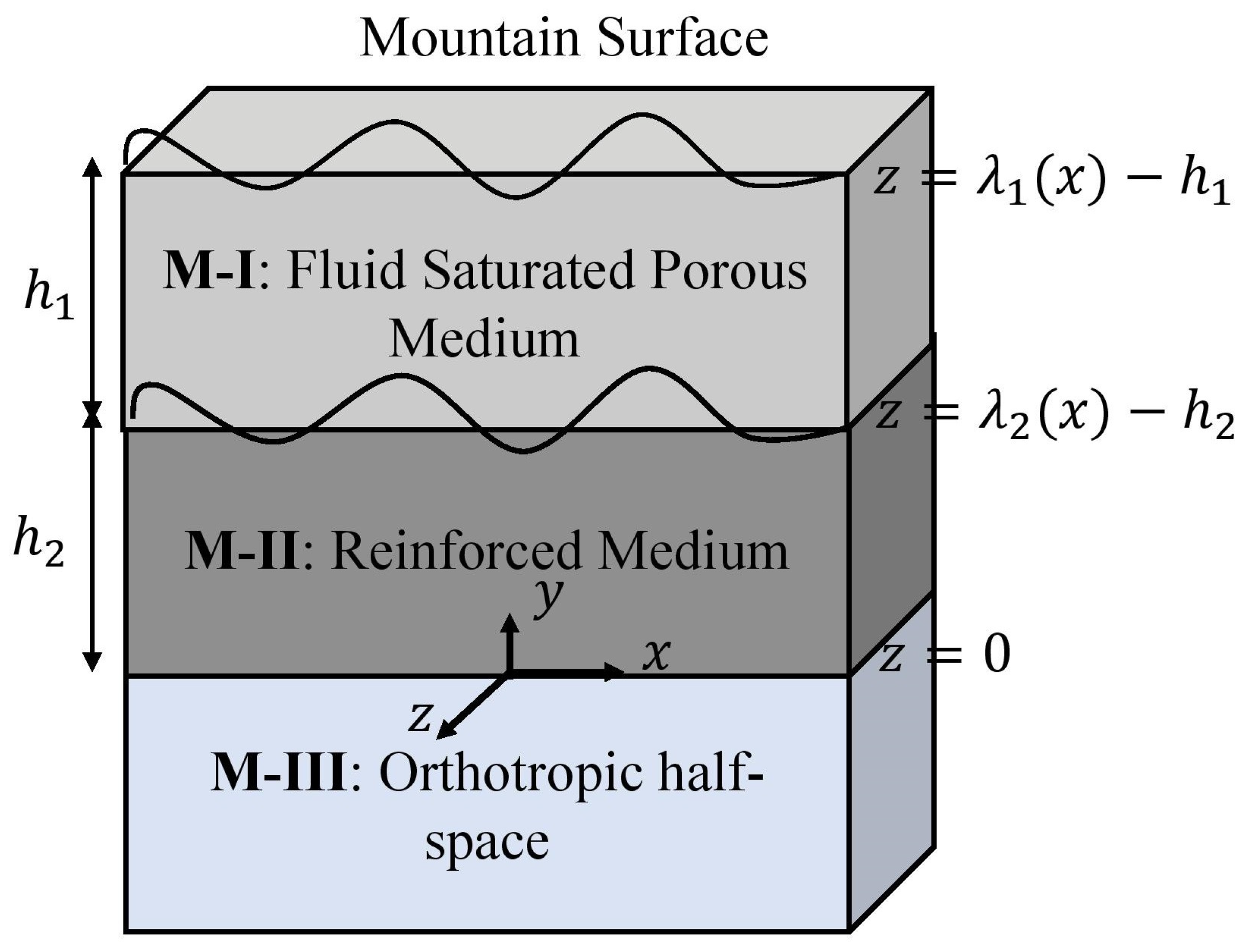
The dynamics of SH-wave propagation depend on the type of irregularity present at the surface and the interface. To observe the phase velocity under the influence of the discontinuous boundaries, we considered a periodic irregularity at the free surface ( z = λ 1 ( x ) h 1 ) and at the interface, ( z = λ 2 ( x ) h 2 ) of the medium (as shown in Figure 1). The periodic irregularity λ j ( x ) may express as the Fourier series expression as provided by Singh [25] as
λ j ( x ) = Σ n = 1 λ n j e i n k x + λ n j e i n k x , j = 1 , 2 .
Here, λ n j and λ n j are Euler coefficients, n is the order of series, k is the wave number, and i = 1 . The composite materials are used as the medium of the wave propagation under irregular boundaries. The dynamics of the wave propagation is described by the Cartesian coordinates system, originating at the second interface of the medium. The wave propagation is taken along the x -direction and the z -axis is taken along the depth of the mediums. The mechanical displacement may derive along the y -direction. Hence, the non-vanishing quantities which represent the motion are functions of x, z, and t only. The approximate thickness of the porous layer and reinforced medium is taken as h 1 and h 2 , respectively, and the orthotropic materials are used in the semi-infinite medium ( z ) .

3. Mechanics of Wave Propagation and Governing Equations of Motion

We assumed x -axis as the direction of wave propagation. Hence, the displacement of composite materials will be observed in y -direction only. That is, u n = u n ( x , z , t ) = 0 , v n = v n ( x , z , t ) , w n = w n ( x , z , t ) = 0 ; here, u, v, and w are displacement components along x, y, and z -directions, respectively, and n = 1 , 2 , 3 stands for M-I, M-II, M-III. The non-vanishing governing equations of motion for porous medium under the effect of initial stress are given by Vaishnav [9] as
σ 21 ( 1 ) x + σ 22 ( 1 ) y + σ 23 ( 1 ) z P 1 w z x = 2 t 2 ρ 11 v 1 + ρ 12 V y ,
s y = 2 t 2 ρ 11 v 1 + ρ 22 V y .
Assuming that the liquid and solid components of porous materials do not move in relation to one another, we assumed that the mass coefficients that represent the inertial effects of moving fluids are directly proportional to the shear moduli of the solid and fluid components of the medium. The mass coefficients are ρ 11 , ρ 12 , and ρ 22 , and the densities of the solid and fluid parts are represented by ρ s and ρ f , respectively. The combined density of the porous medium is ρ 1 = ρ s + f ( ρ f ρ s ) with the relations ρ 11 = ( 1 f ) ρ s ρ 12 and ρ 12 = f ρ f ρ 22 and restrictions ρ 11 > 0 , ρ 12 0 , ρ 22 > 0 , and ρ 11 ρ 22 ρ 12 2 > 0 .
The non-vanishing wave equation in a reinforced medium may be expressed as [7]
σ 21 ( 2 ) x + σ 22 ( 2 ) y + σ 23 ( 2 ) z = ρ 2 2 v 2 t 2 ,
and the governing equation of motion for the orthotropic medium is [9]
σ 21 ( 3 ) x + σ 22 ( 3 ) y + σ 23 ( 3 ) z = ρ 3 2 v 3 t 2 .

Stress–Strain Relations for Composite Materials

The stress–strain relation for the water-saturated anisotropic porous medium is given as follows [7]:
σ 11 ( 1 ) = ( α + P 1 ) e 11 + ( α 2 N 1 + P 1 ) e 22 + ( β + P 1 ) e 33 + C E , σ 22 ( 1 ) = ( α 2 N 1 ) e 11 + α e 22 + β e 33 + C E , σ 33 ( 1 ) = β e 11 + β e 22 + γ e 33 + C E , σ 12 ( 1 ) = 2 N 1 e 12 , σ 23 ( 1 ) = 2 L 1 e 23 , σ 13 ( 1 ) = 2 L 1 e 31 ,
here, e i j = 1 2 u i x j + u j x i , σ i j ( 1 ) represents the strain and stress components of the superficial layer, respectively, and E = U x x + U y y + U z z . α , β , γ are elastic constants of the porous material; N 1 , L 1 are shear moduli of the anisotropic porous material in x- and z-directions, respectively; and C > 0 denotes the strength of the relationship between the volume changes in solids and liquids. The physical meaning of the notations is mentioned in Table 1.
The stress–strain relation in the reinforced medium is given by
σ i j ( 2 ) = λ ¯ e k k δ i j + 2 μ T e i j + α ¯ a k a m e k m δ i j + e k k a i a j + 2 ( μ L μ T ) ( a i a k e k j + a j a k e k i ) + β ¯ a k a m e k m a i a j ,
for all i, j, k, m = 1, 2, 3. Here, σ i j ( 2 ) are stress components of M-II; λ ¯ , α ¯ , β ¯ are elastic constants of the reinforced medium; e i j are strain components; δ i j = Kronecker delta; a = ( a 1 , a 2 , a 3 ) = preferred direction of reinforcement such that a 1 2 + a 2 2 + a 3 2 = 1 ; μ L and μ T are the transverse and longitudinal shear moduli in the preferred direction.
For SH-waves propagation along x -direction, the non-vanishing stress–strain relations in reinforced layer are
σ 12 ( 2 ) = 2 μ T e 12 + 2 ( μ L μ T ) ( a 1 a k e k 2 ) , σ 22 ( 2 ) = 0 , σ 23 ( 2 ) = 2 μ T e 23 + 2 ( μ L μ T ) ( a 3 a k e k 2 ) .
There are three mutually orthogonal planes of symmetry in an orthotropic material due to its anisotropic nature. For the orthotropic medium, the stress–strain relation is given by Wang [1] as
σ 11 ( 3 ) σ 22 ( 3 ) σ 33 ( 3 ) τ 23 τ 13 τ 12 = c 11 c 12 c 13 0 0 0 c 12 c 22 c 23 0 0 0 c 13 c 23 c 33 0 0 0 0 0 0 c 44 0 0 0 0 0 0 c 55 0 0 0 0 0 0 c 66 ε 11 ε 22 ε 33 γ 23 γ 13 γ 12
where σ 11 ( 3 ) , σ 22 ( 3 ) , and σ 33 ( 3 ) are normal stresses; τ 23 , τ 13 , and τ 12 are shear stresses; ε 11 , ε 22 , and ε 33 are normal strains; γ 23 , γ 13 , and γ 12 are shear strain; c i j are elasticity constants of orthotropic medium. The relationship of Young’s moduli ( E j ) and Poisson’s ratio ( ν i j ) is ν i j / E i = ν j i / E j . Hence, the elasticity constants c i j may express as
c 11 = E 1 ( ν 23 ν 31 1 ) ν 12 ( ν 21 + ν 23 ν 31 ) + ν 23 ν 31 + ν 13 ( ν 31 + ν 21 ν 32 ) 1 ,
c 12 = E 1 ( ν 21 + ν 23 ν 31 ) ν 12 ( ν 21 + ν 23 ν 31 ) + ν 23 ν 31 + ν 13 ( ν 31 + ν 21 ν 32 ) 1 ,
c 13 = E 1 ( ν 31 + ν 21 ν 32 ) ν 12 ( ν 21 + ν 23 ν 31 ) + ν 23 ν 31 + ν 13 ( ν 31 + ν 21 ν 32 ) 1 ,
c 22 = E 2 ( ν 13 ν 31 1 ) ν 12 ( ν 21 + ν 23 ν 31 ) + ν 23 ν 31 + ν 13 ( ν 31 + ν 21 ν 32 ) 1 ,
c 23 = E 2 ( ν 32 + ν 12 ν 31 ) ν 12 ( ν 21 + ν 23 ν 31 ) + ν 23 ν 31 + ν 13 ( ν 31 + ν 21 ν 32 ) 1 ,
c 33 = E 3 ( ν 12 ν 21 1 ) ν 12 ( ν 21 + ν 23 ν 31 ) + ν 23 ν 31 + ν 13 ( ν 31 + ν 21 ν 32 ) 1 ,
c 44 = G 23 , c 55 = G 13 , c 66 = G 12 ,
where G i j represents the shear moduli of M-III.
The strain–displacement relationship for an orthotropic semi-infinite medium are
ε x x = u x x , ε y y = u y y , ε z z = u z z
γ x y = u y x u x y , γ y z = u z y u y z , γ x z = u z x u x z
where u x , u y , and u z are displacement components of the orthotropic materials along the axis of the Cartesian coordinate system.

4. Displacement of Composite Materials

The displacement components along y -direction in solid and liquid porous materials are assumed as v 1 ( x , z , t ) and V 1 ( x , z , t ) , respectively, and v 2 ( x , z , t ) and v 3 ( x , z , t ) represent the displacement components in the reinforced and orthotropic layers. The general solution of equations of motion (Equations (2)–(5)) will be the resultant displacement in respective mediums. Using stress–strain relation (Equation (6)) and standard SH-waves conditions into Equations (2) and (3), we obtain
N 1 P 1 2 2 v 1 x 2 + L 1 2 v 1 z 2 = ρ 1 2 v 1 t 2 ,
2 ( ρ 12 v 1 + ρ 22 V 1 ) t 2 = 0 ,
and ρ 12 v 1 + ρ 22 V 1 = D , hence V 1 = ( D ρ 12 v 1 ) / ρ 22 , ρ 1 = ρ 11 ρ 12 2 ρ 22 , 2 t 2 ρ 11 v 1 + ρ 12 V 1 = ρ 1 2 v 1 t 2 .
Using stress–strain relation (Equation (7)) of reinforced materials and SH-waves propagation conditions into Equation (4), we have
P 2 v 2 x 2 + 2 Q 2 v 2 x z + R 2 v 2 z 2 = ρ 2 2 v 2 t 2 ,
where P = μ T + ( μ L μ T ) a 1 2 , Q = a 1 a 3 ( μ L μ T ) , R = μ T + ( μ L μ T ) a 3 2 .
Using stress–strain relation (Equation (8)) of orthotropic medium and standard SH-waves conditions into Equation (5), we obtain
c 66 2 v 3 x 2 + c 44 2 v 3 z 2 = ρ 3 2 v 3 t 2 .
Assuming the solution of (10)–(13) as
v 1 = F ( z ) e i k ( x c t ) ,
v 2 = G ( z ) e i k ( x c t ) ,
v 3 = H ( z ) e i k ( x c t ) ,
where F, G, and H are the functions of z only, and e i k ( x c t ) is a function of x and t with wave number k, phase velocity c and i = 1 . Substituting Equations (14)–(16) into Equations (10), (12), and (13), respectively, we obtain
d 2 F ( z ) d z 2 + S 1 2 F ( z ) = 0 ,
P d 2 G ( z ) d z 2 + 2 i k Q d G ( z ) d z + k 2 ( ρ 2 c 2 P ) G ( z ) = 0 ,
d 2 H ( z ) d z 2 S 3 2 H ( z ) = 0 .
where S 1 = k c 2 d N P 1 2 L = k g d c 2 c 1 2 1 ζ d , S 3 = k c 66 c 44 c 2 c 3 2 , g = N 1 L 1 , ζ = P 1 2 L 1 , c 1 2 = N 1 ρ 1 , and k is the wave number. d represents the porosity of the incompressible porous layer. A porous medium may classify as the following:
i.
For the non-porous solid, the porosity (d) of the medium approaches 1.
ii.
For the fluid form of the porous medium, d 0 .
iii.
For the poroelastic medium, the range of the porosity is 0 < d < 1 .
The phase velocity of porous medium is c 1 = L 1 / ρ 1 is the phase velocity of the M-I and c 3 = c 44 / ρ 3 is the phase velocity of the M-III. The general solution of the Equations (17)–(19) was obtained analytically as
F ( z ) = A 1 cos S 1 z + A 2 sin S 1 z ,
G ( z ) = A 3 e i k S 2 z + A 4 e i k S 2 z ,
H ( z ) = A 5 e S 3 z + A 6 e S 3 z ,
where S 2 = 1 R Q + M 1 , S 2 = 1 R Q + M 1 , M 1 = Q 2 + R ( ρ 2 c 2 P ) , and A 1 to A 6 are arbitrary constants.
The displacement v 1 of the medium M-I is derived as
v 1 = A 1 cos ( S 1 z ) + A 2 sin ( S 1 z ) e i k ( x c t ) .
The displacement v 2 of the medium M-II is derived as
v 2 = A 3 e i k S 2 z + A 4 e i k S 2 z e i k ( x c t ) .
The bounded ( z ) displacement v 3 ( x , z , t ) in orthotropic stratum is calculated as
v 3 = A 5 e S 3 z e i k ( x c t ) .

5. Continuity Conditions

The continuity conditions on the geometry of the problem are as follows:
  • The upper surface ( z = λ 1 ( x ) h 1 ) of the superficial layer (M-I) is stress free, i.e.,
    σ 23 ( 1 ) λ 1 σ 12 ( 1 ) = 0 .
  • The stress components of the porous medium (M-I) and reinforced medium (M-II) are continuous at the contact interface z = λ 2 ( x ) h 2 , i.e.,
    σ 23 ( 1 ) λ 1 σ 12 ( 1 ) = σ 23 ( 2 ) λ 2 σ 12 ( 2 ) .
  • At the first interface ( z = λ 2 ( x ) h 2 ) of the medium, the components of mechanical displacement are continuous, i.e.,
    v 1 ( x , z , t ) = v 2 ( x , z , t )
  • The stress components of M-II and M-III are continuous at the contact interface z = 0 , i.e.,
    σ 12 ( 2 ) + σ 23 ( 2 ) = σ 23 ( 3 ) .
  • The displacement components of M-II and M-III are continuous at the contact interface z = 0 , i.e.,
    v 2 ( x , z , t ) = v 3 ( x , z , t )

6. Generalized Dispersion Relation

The equations of phase velocity for the propagation of SH waves in composite materials structure under the mountain surfaces may derive by applying continuity conditions on the displacement Equations (23)–(25).
The phase velocity equations at the irregular surface z = λ 1 ( x ) h 1 are obtained as
L 1 S 1 sin ( S 1 ( λ 1 ( x ) h 1 ) ) i k λ 1 N 1 cos ( S 1 ( λ 1 ( x ) h 1 ) ) A 1
+ L 1 S 1 cos ( S 1 ( λ 1 ( x ) h 1 ) ) i k λ 1 N 1 sin S 1 ( λ 1 ( x ) h 1 ) A 2 = 0 ,
at the interface z = λ 2 ( x ) h 2 , the phase velocity equations may obtained as
L 1 S 1 sin ( S 1 ( λ 2 ( x ) h 2 ) ) i k λ 2 N 1 cos ( S 1 ( λ 2 ( x ) h 2 ) ) A 1
+ L 1 S 1 cos ( S 1 ( λ 2 ( x ) h 2 ) ) i k λ 2 N 1 sin S 1 ( λ 2 ( x ) h 2 ) A 2
= ( R λ 2 Q ) S 2 + ( Q λ 2 P ) i k e i k S 2 ( λ 2 ( x ) h 2 ) A 3
+ ( R λ 2 Q ) S 2 + ( Q λ 2 P ) i k e i k S 2 ( λ 2 ( x ) h 2 ) A 4 ,
cos ( S 1 ( λ 2 ( x ) h 2 ) ) A 1 + sin ( S 1 ( λ 2 ( x ) h 2 ) ) A 2 e i k S 2 ( λ 2 ( x ) h 2 ) A 3
e i k S 2 ( λ 2 ( x ) h 2 ) A 4 = 0 .
The phase velocity relations on the points lying on the common interface ( z = 0 ) of M-II and M-III may be derived as
i k ( R S 2 + Q ) A 3 + i k ( R S 2 + Q ) A 4 + c 44 S 3 A 5 = 0
A 3 + A 4 A 5 = 0 .
For the generalized dispersion relation of SH waves in the composite structure under the mountain surfaces, we are required to find the non-trivial solution of the above system of linear equations, i.e.,
a 11 a 12 0 0 0 a 21 a 22 a 23 a 24 0 a 31 a 32 a 33 a 34 0 0 0 a 43 a 44 a 45 0 0 a 53 a 54 a 55 = 0 ,
where a i j are coefficients of A j , i , j = 1 , 2 , 3 , 4 , 5 . Therefore, we derived the dispersion relation as
i e i k M 1 ( λ 2 ( x ) h 2 ) / R + e i k M 1 ( λ 2 ( x ) h 2 ) / R [ μ T N 1 2 M 1 ¯ λ 1 λ 2 μ T L 1 2 S 1 2 M 1 M 1 ¯
μ T 2 N 1 M 1 M 1 ¯ λ 1 M 3 ¯ + L 1 c 44 μ T S 1 S 3 M 1 M 2 ¯ M 4 ¯ + i { μ T M 1 L 1 S 1 N 1 λ 2 M 2 ¯
μ T M 1 L 1 S 1 N 1 λ 1 M 2 ¯ μ T M 1 L 1 S 1 M 2 ¯ M 4 ¯ c 44 S 3 λ 1 N 1 M 1 ¯ M 3 ¯ } ]
+ e i k M 1 ( λ 2 ( x ) h 2 ) / R e i k M 1 ( λ 2 ( x ) h 2 ) / R [ L 1 2 c 44 S 1 2 S 3 M 1 ¯ c 44 N 1 2 S 3 M 1 ¯ λ 1 λ 2
+ μ T c 44 N 1 S 3 λ 1 M 1 ¯ M 3 ¯ + L 1 μ T 2 S 1 M 1 2 M 2 ¯ M 4 ¯ + i { c 44 S 3 L 1 N 1 S 1 λ 1 M 2 ¯
c 44 S 3 L 1 N 1 S 1 λ 2 M 2 ¯ + L 1 S 1 c 44 S 3 M 2 ¯ M 4 ¯ μ T 2 M 1 2 N 1 λ 1 M 1 ¯ M 3 ¯ } ] = 0 .
Equation (36) represents the complex form of generalized dispersion relation in the multi-layered structure under the mountain surfaces. So, the wave number must be a complex value. By equating the real part of the Equation (36), the dispersion relation of SH-waves propagation may be obtained as
i e i k M 1 ( λ 2 ( x ) h 2 ) / R + e i k M 1 ( λ 2 ( x ) h 2 ) / R μ T N 1 2 M 1 ¯ λ 1 λ 2 μ T L 1 2 S 1 2 M 1 M 1 ¯
μ T 2 N 1 M 1 M 1 ¯ λ 1 M 3 ¯ + L 1 c 44 μ T S 1 S 3 M 1 M 2 ¯ M 4 ¯
+ e i k M 1 ( λ 2 ( x ) h 2 ) / R e i k M 1 ( λ 2 ( x ) h 2 ) / R L 1 2 c 44 S 1 2 S 3 M 1 ¯ c 44 N 1 2 S 3 M 1 ¯ λ 1 λ 2
+ μ T c 44 N 1 S 3 λ 1 M 1 ¯ M 3 ¯ + L 1 μ T 2 S 1 M 1 2 M 2 ¯ M 4 ¯ = 0 .
The compact form of the obtained generalized dispersion relation (Equation (37)) may be written as
tan k χ = χ 1 χ 2 ,
where
χ = ( λ 2 h 2 ) M 1 M 2 ,
χ 1 = μ T N 1 2 M 1 ¯ λ 1 λ 2 μ T L 1 2 S 1 2 M 1 M 1 ¯ μ T 2 N 1 M 1 M 1 ¯ λ 1 M 3 ¯ + L 1 c 44 μ T S 1 S 3 M 1 M 2 ¯ M 4 ¯ ,
χ 2 = L 1 2 c 44 S 1 2 S 3 M 1 ¯ c 44 N 1 2 S 3 M 1 ¯ λ 1 λ 2 + μ T c 44 N 1 S 3 λ 1 M 1 ¯ M 3 ¯ + L 1 μ T 2 S 1 M 1 2 M 2 ¯ M 4 ¯ ,
M 1 = a 1 2 a 3 2 μ L μ T 1 2 + 1 + μ L μ T 1 a 3 2 c 2 c 2 2 μ L μ T 1 a 1 2 ,
M 2 = 1 + μ L μ T 1 a 3 2 ,
M 1 ¯ = sin S 1 ( k h 1 ϵ 1 h 1 cos ( ϵ h 1 x h 1 ) k h 2 ϵ 2 h 2 cos ( ϵ h 2 x h 2 ) + k h 2 k h 1 ) ,
M 2 ¯ = cos S 1 ( k h 1 ϵ 1 h 1 cos ( ϵ h 1 x h 1 ) k h 2 ϵ 2 h 2 cos ( ϵ h 2 x h 2 ) + k h 2 k h 1 ) ,
M 3 ¯ = a 1 2 a 3 2 μ L μ T 1 2 1 + μ L μ T 1 a 1 2 1 + μ L μ T 1 a 3 2 M 2 ,
M 4 ¯ = 1 λ 2 a 1 a 3 μ L μ T 1 1 + μ L μ T 1 a 3 2 ,
λ 1 = ϵ h 1 ϵ 1 h 1 sin ( ϵ h 1 x h 1 ) ,
λ 2 = ϵ h 2 ϵ 2 h 2 sin ( ϵ h 2 x h 2 ) .

7. Particular Cases

7.1. Case-1

In this case, suppose the porous surface is regular and the contact interface of M-I and M-II is periodic, i.e., λ 1 = 0 , λ 1 = 0 , λ 2 = ξ 2 cos ϵ x , and λ 2 = ξ 2 ϵ sin ϵ x . The generalized dispersion equation reduced to
t a n [ k χ ] = μ T L 1 2 S 1 2 M 1 M 1 ¯ + L 1 c 44 μ T S 1 S 3 M 1 M 2 ¯ M 4 ¯ L 1 2 c 44 S 1 2 S 3 M 1 ¯ + L 1 μ T 2 S 1 M 1 2 M 2 ¯ M 4 ¯
Equation (39) represents the relation between the frequency and the phase velocity of SH waves. Equation (39) depends on the initial stress and porosity of the superficial layer (M-I), reinforcement of the intermediate layer (M-II), depth of M-I and M-II, and amplitude of the first periodic irregular interface. For the existence of SH-waves propagation, the phase velocity of the wave must satisfy c 1 c 2 c c 3 .

Subcase-1.1

If the M-I is stress free ( P 1 2 L 1 ) , non-porous ( d 1 ) , and isotropic ( N 1 = L 1 = μ 1 ) , then the dispersion relation (39) converts to
t a n [ k χ ] = μ T μ 1 2 S 1 ¯ 2 M 1 M 1 ¯ ¯ + μ 1 c 44 μ T S 1 ¯ S 3 M 1 M 2 ¯ ¯ M 4 ¯ μ 1 2 c 44 S 1 ¯ 2 S 3 M 1 ¯ ¯ + μ 1 μ T 2 S 1 ¯ M 1 2 M 2 ¯ ¯ M 4 ¯
where
M 1 ¯ ¯ = sin S 1 ¯ ( k h 2 ϵ 2 h 2 cos ( ϵ h 2 x h 2 ) + k h 2 k h 1 ) ,
M 1 ¯ ¯ = cos S 1 ¯ ( k h 2 ϵ 2 h 2 cos ( ϵ h 2 x h 2 ) + k h 2 k h 1 ) ,
S 1 ¯ = c 2 c 1 2 1 .

7.2. Case-2

If the first interface is continuous (i.e., z = h 2 ) and upper surface of M-I is periodic irregular, i.e., λ 2 = 0 , λ 2 = 0 , λ 1 = ξ 2 cos ϵ x , and λ 1 = ξ 1 ϵ sin ϵ x , then Equation (41) takes the form
t a n k h 2 M 1 M 2 = μ T L 1 2 S 1 2 M 1 M 1 ¯ μ T 2 N 1 M 1 M 1 ¯ λ 1 M 3 ¯ + L 1 c 44 μ T S 1 S 3 M 1 M 2 ¯ M 4 ¯ L 1 2 c 44 S 1 2 S 3 M 1 ¯ + μ T c 44 N 1 S 3 λ 1 M 1 ¯ M 3 ¯ + L 1 μ T 2 S 1 M 1 2 M 2 ¯ M 4 ¯
Equation (41) depends on the amplitude of the reinforcement and a periodic irregular porous surface.

7.3. Case-3

If the free surface and first interface are continuous, i.e., λ 1 = 0 and λ 2 = 0 , λ 1 = 0 and λ 2 = 0 . Then, Equation (41) reduces to
t a n k h 2 M 1 M 2 = μ T L 1 2 S 1 2 M 1 M 1 ¯ + L 1 c 44 μ T S 1 S 3 M 1 M 2 ¯ L 1 2 c 44 S 1 2 S 3 M 1 ¯ + L 1 μ T 2 S 1 M 1 2 M 2 ¯

7.3.1. Subcase-3.1

If the M-I is initial stress free P 1 / 2 L 1 = 0 , isotropic ( N 1 = L 1 = μ 1 ) , and non-porous ( d 1 ) -type material; M-II is isotropic ( μ L = μ T = μ 2 ) , non-reinforced ( a 1 2 = 0 and a 3 2 = 0 ); and M-III is isotropic ( c 66 = c 44 = μ 3 ) , then the dispersion relation (Equation (38)) becomes
t a n k h 2 c 2 c 2 2 1 = μ 2 μ 1 2 S 1 ¯ 2 c 2 c 2 2 1 M 1 ¯ + μ 1 μ 3 μ 2 S 1 ¯ S 3 ¯ M 1 M 2 ¯ μ 1 2 μ 3 S 1 ¯ 2 S 3 ¯ M 1 ¯ + μ 1 μ 2 2 S 1 ¯ c 2 c 2 2 1 M 2 ¯

7.3.2. Subcase-3.2

The classical dispersion relation of the Love wave may obtain from Equation (43) by taking h 1 0 and μ 1 0 . From generalized dispersion relation in particular cases, the standard dispersion relation of Love wave is obtained from (38) as
t a n k h 2 c 2 c 2 2 1 = μ 3 μ 2 1 c 2 c 3 2 c 2 c 2 2 1 .
Love [3] derived the standard dispersion relation for the propagation of the Love wave. Love waves may propagate in the presence of a superficial layer (homogeneous isotropic medium) and half-space (homogeneous isotropic).

8. Numerical Computations and Discussions

The present study investigates the behavior of shear waves in the multi-layered structure of composite materials. We obtained the frequency relation of the SH wave analytically to reveal the hidden properties of the SH-wave propagation in the multi-materials structure. The resulting frequency relation matches the classical form of the Love wave propagation very well, which verifies the current work. The essential numerical values for the graphical depiction of the frequency relation are taken from Table 2. The relationship between the phase velocity and the frequency of the wave is demonstrated in this section under various affecting parameters.

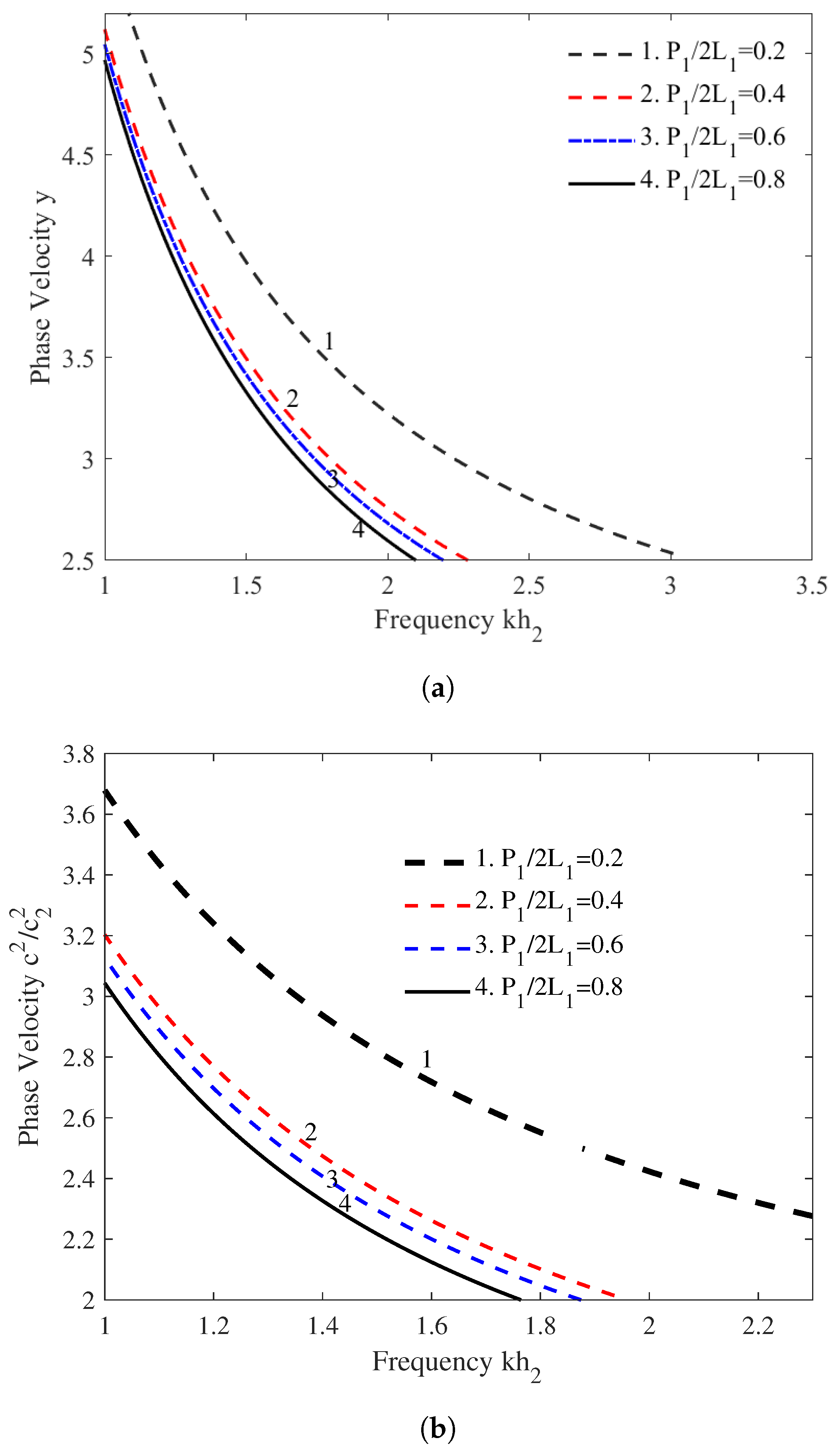
8.1. Effect of the Initial Stress in Both Cases

The impact of the initial stress parameter ( P 1 / 2 L 1 ) associated with the fiber-reinforced materials (M-II) on the phase velocity of the SH waves is examined under regular and irregular boundaries. The influence of said parameter under regular and irregular boundaries is depicted in Figure 2a,b, respectively. The phase velocity of the SH wave decreases due to the high initial stress of the fiber-reinforced medium under regular and irregular boundaries. It is observed that, for the wide range of the frequency, the initial stress has a substantial effect on the phase velocity curves, whereas a moderate effect of said parameter is noticed for the low frequency of the SH wave in both circumstances. The effect of the initial stress is more significant for the low-frequency range with irregular boundaries than with regular boundaries, as shown in Figure 2b. The stress–strain curve’s slope increases with an increase in the initial stress from a zero condition because the added initial stress closes the gaps between the components. An estimated presentation of the rock material will not happen until then. Therefore, during the SH-wave propagation under regular and irregular boundaries, the impact of the initial stress may not be ignored.

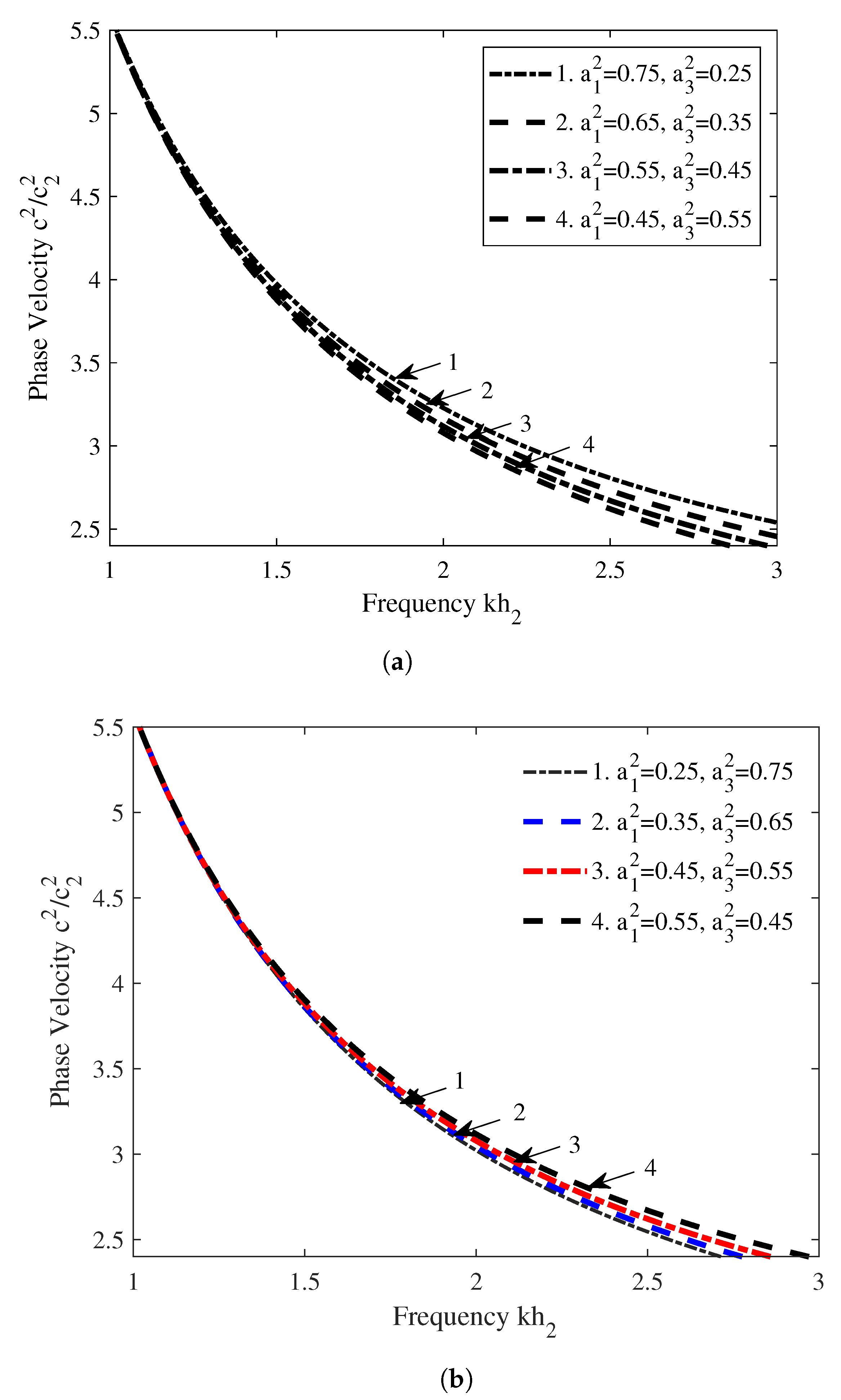
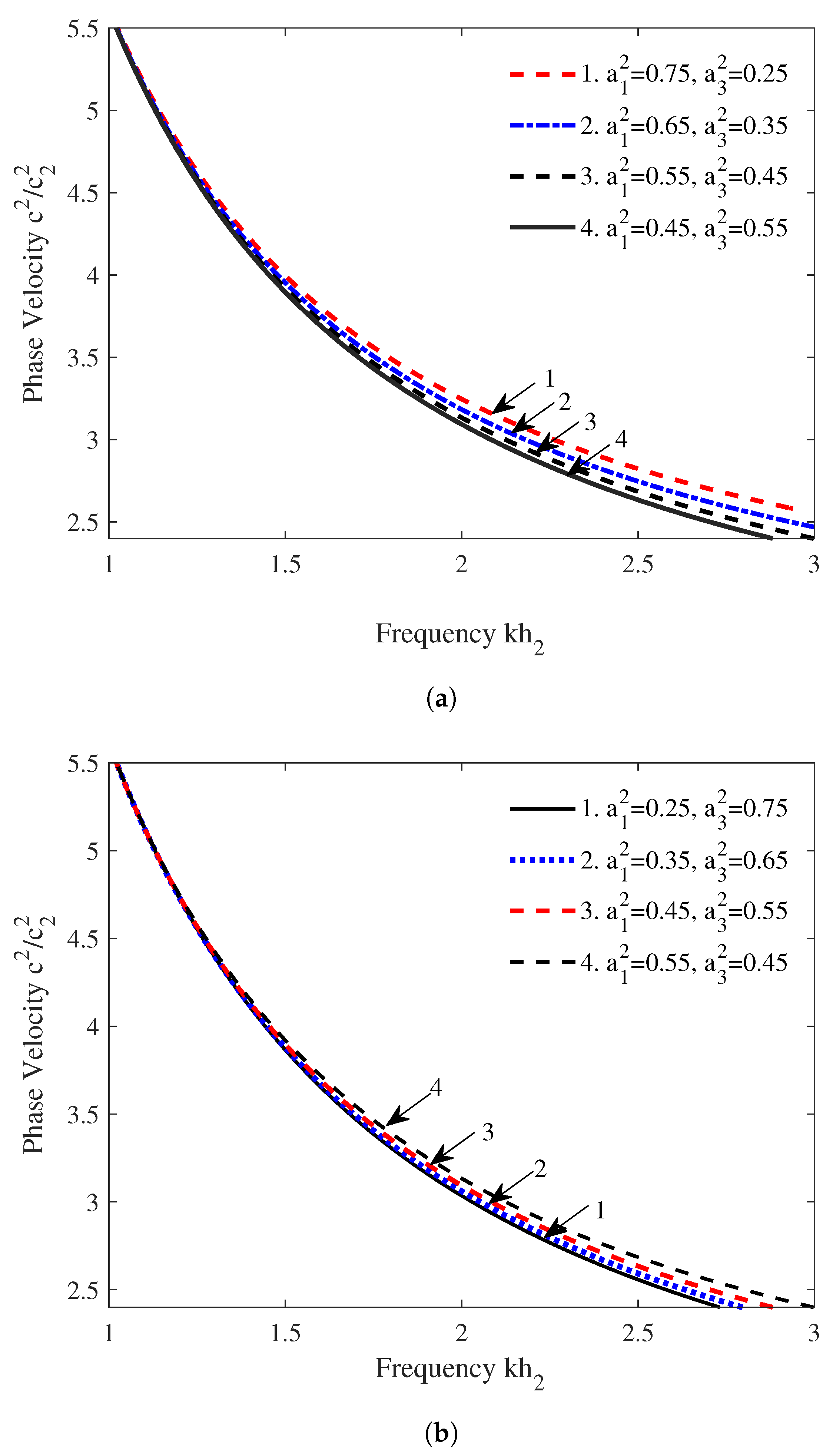
8.2. Effect of the Reinforced Parameters in Both Cases

An intermediate layer of the proposed Earth schematic contains fiber-reinforced materials for h 1 < z < h 2 . The effect of the reinforced parameters a 1 and a 3 with the reinforcement condition a 1 2 + a 2 2 + a 3 2 = 1   ( a 2 = 0 ) on the phase velocity of the SH wave under regular boundaries are depicted in Figure 3a,b, and under irregular boundaries, the effect of said parameters are demonstrated in Figure 4a,b, respectively. The phase velocity of the SH wave increases as the values of the parameters a 1 2 and a 3 2 increase, whereas the phase velocity of the SH wave decreases as the values of the parameters a 1 2 and a 3 2 decrease in both conditions, as shown in Figure 3a,b and Figure 4a,b, respectively. It is observed that the influence of the reinforced parameters on the phase velocity of the shear wave remains analogous in both cases.

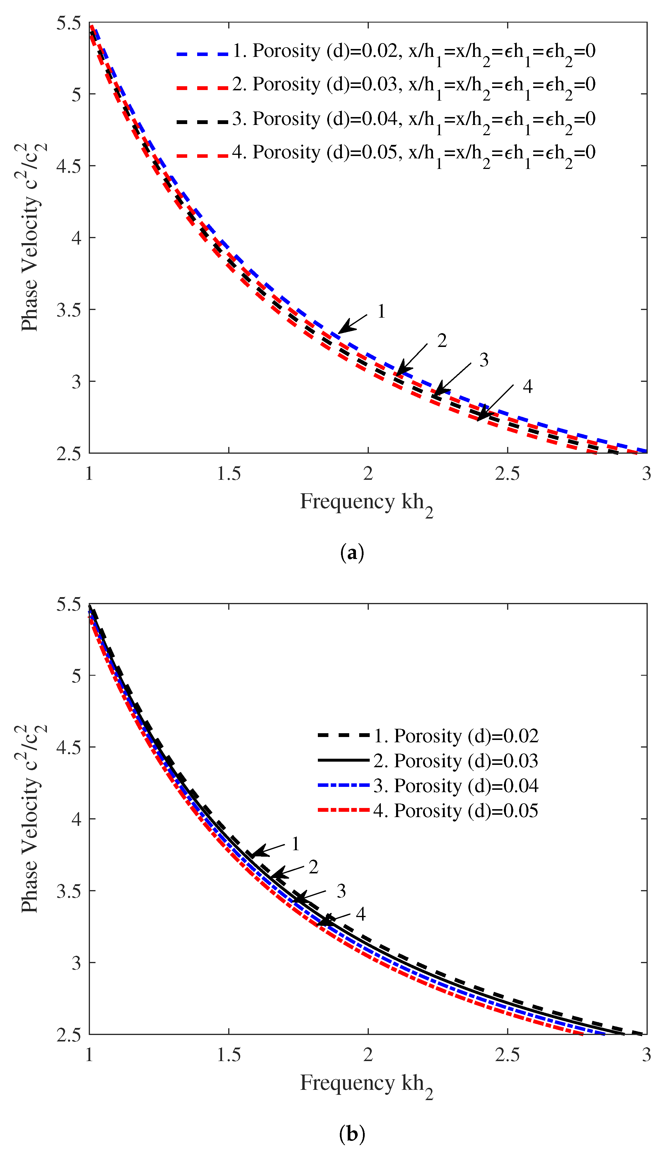
8.3. Effect of the Porosity in Both Cases

Figure 5a,b manifest the impact of the porosity under regular and irregular boundaries on the phase velocity curves. The guiding layer of the schematic contains the porous materials for z = h 1 . The impact of the porosity on the phase velocity of the SH wave is examined by plotting four different curves of the dispersion relation for the different values of the porosity parameter ( d 1 = 0.02 , 0.03 , 0.04 , 0.05 ) in both cases. In the case of the regular boundaries, the irregularity parameters x / h 1 , x / h 2 , ϵ / h 1 , and ϵ / h 2 are taken as zero, and in the case of the irregular boundaries, the values of these parameters are taken as x / h 1 = 0.02 , x / h 2 = 0.10 , ϵ / h 1 = 1.2 , and ϵ / h 2 = 1.2 . It has been shown that the porosity of the porous medium has a considerable effect for the frequency range k h 2 > 2 and a very low effect for the frequency range k h 2 < 2 . Hence, the porosity of the medium does not affect the phase velocity of the SH wave significantly, but it decreases the phase velocity of the SH wave slightly in both cases.

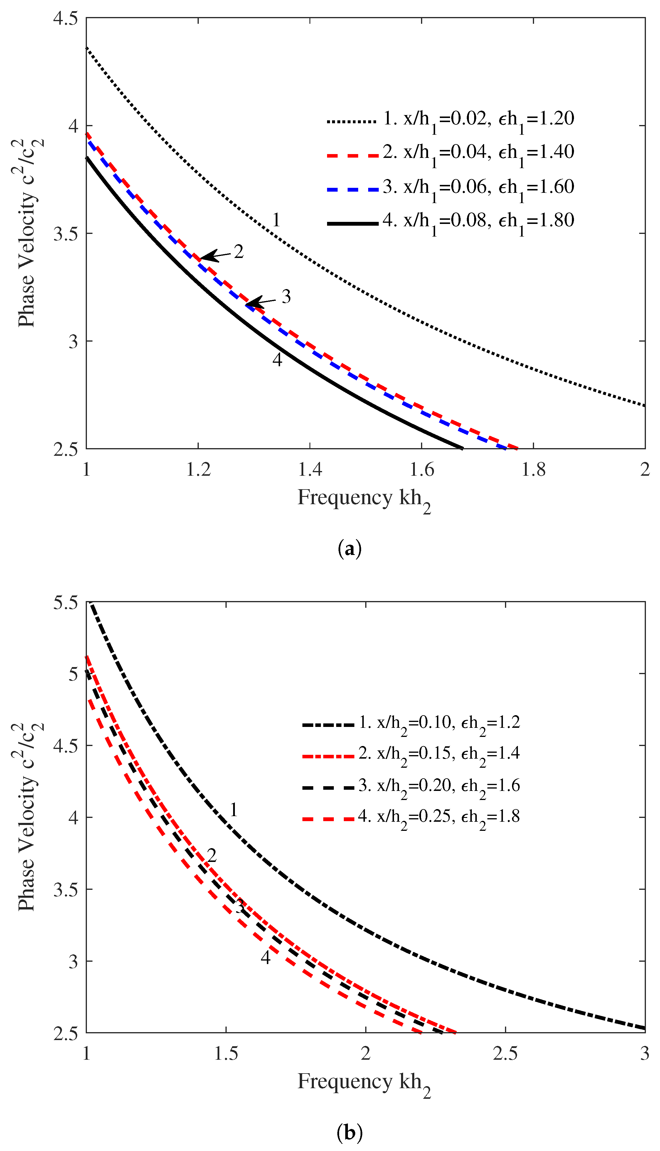
8.4. Effect of the Irregularity Parameters

We considered the periodic irregularity at the free surface of the guiding layer and at the interface of M-I and M-II that may be represented by the parameters x / h 1 , ϵ h 1 , and x / h 2 , ϵ h 2 , respectively. The direct effect of these parameters on the phase velocity of the shear wave is manifested in Figure 6a,b. The discontinuity in the multi-layered composite materials structure decreases the phase velocity of the SH wave significantly with respect to the wave numbers. The first two curves of Figure 6 show the diverse behavior of the phase velocity of the SH wave due to the periodicity of the irregular medium, whereas this effect is moderate for the other curves of Figure 6. Within the high range of the frequency, the impact of the irregularity on the phase velocity is quite strong; nevertheless, for the lower range, it behaves as expected. Hence, this study recommended that the consideration of the irregularity at the free surface, as well as the interface of the two mediums during the SH-wave propagation, will provide accurate information about the interior structure of the Earth for possible natural minerals.
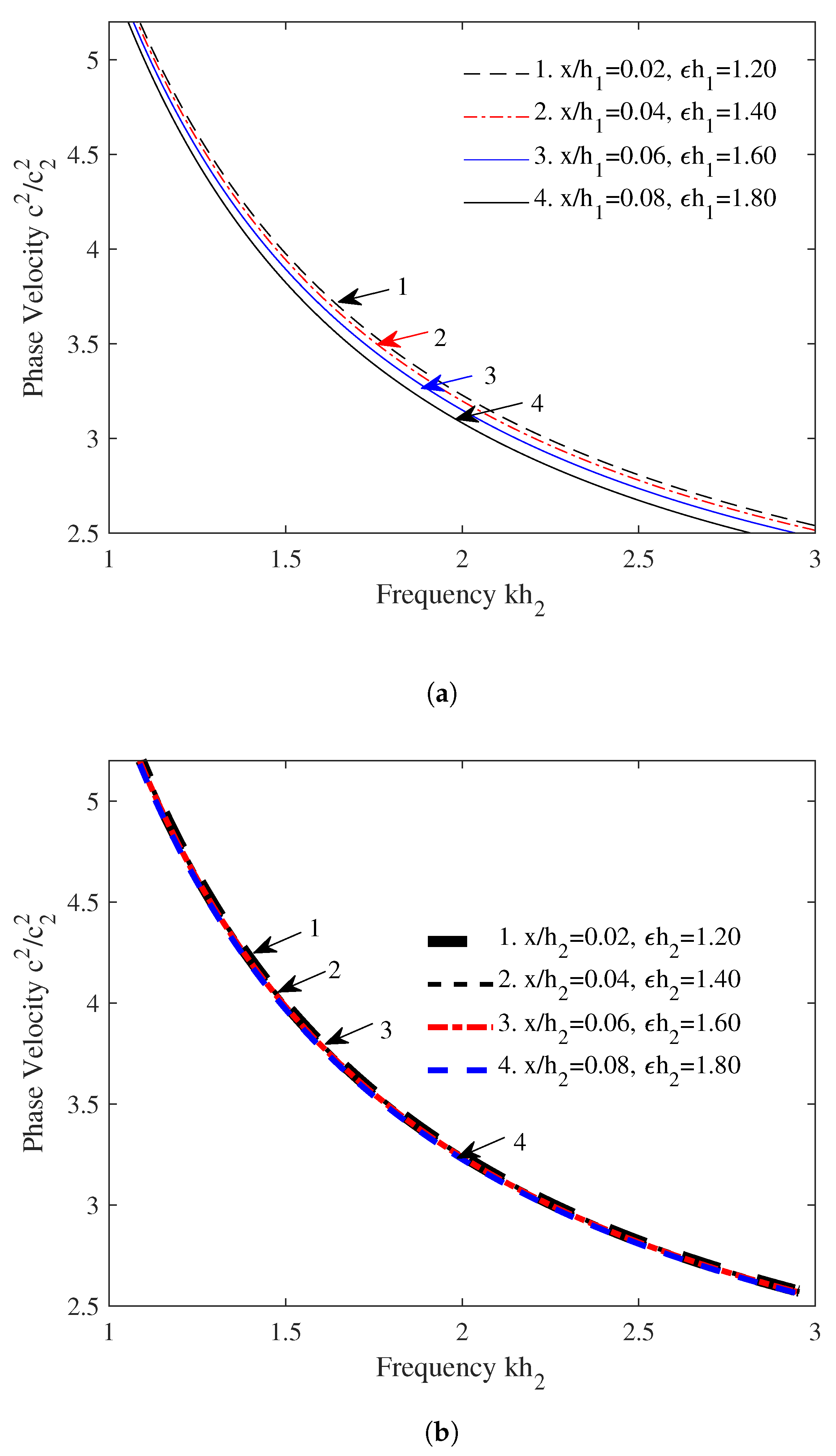
Figure 7a depicts the effect of an irregular free surface when the interface of M-I and M-II is regular, whereas Figure 7b manifests the influence of an irregular interface of M-I and M-II in the case of a regular surface of the guiding layer. In this scenario, a symmetric behavior of the phase velocity curves is observed. However, asymmetric behavior is noticed in Figure 6a,b. Due to multiple irregular borders in the propagation medium, the phase velocity of the SH wave was affected significantly, whereas the effect of the irregularity is moderate in the presence of a single irregular border.

9. Conclusions

The present study derived the dispersion relation of the SH-waves propagation in a composite materials structure under mountain and plain surfaces. Anisotropic materials are used in the composite structure to investigate the influence of the porosity, initial stress, reinforcement, and periodic irregularity on the phase velocity of SH waves. The influence of these parameters is discussed in both cases.
The findings of the current investigation can be summarized as follows:
  • The SH-waves velocity decreases in an incompressible porous medium due to the presence of the initial stress P 1 / 2 L 1 in both cases.
  • It is observed that the phase velocity curves are continuous for 1 < k h 2 < 3 , but the curves are discontinuous for 1.8 < k h 2 < 1.95 . It concludes that the initial stress P 1 / 2 L 1 has more impact under the mountain surfaces.
  • The influence of the irregularity (free surface) parameters ( x / h 1 and ϵ h 1 ) is more significant under the consideration of the irregularity of the interface. However, the influence is moderate in the absence of the irregularity (interface) parameters ( x / h 2 and ϵ h 2 ).
  • The influence of the irregularity (interface) parameters ( x / h 2 and ϵ h 2 ) has more impact in the presence of the irregular surface, and it is negligible in the absence of the irregularity (surface) parameters ( x / h 1 and ϵ h 1 ).
  • The phase velocity of the SH waves increases as the value of the reinforce parameter ( a 1 2 ) increases. However, the phase velocity decreases as the value of the reinforce parameter a 3 2 increases. The effect of the parameters a 1 2 and a 3 2 remains constant for both cases (mountain and plain surfaces).
  • The phase velocity decreases as the value of the porosity ( d ) increases. It has been noticed that the effect of the porosity remains constant for both cases.
Furthermore, the derived dispersion relation is deduced into the conventional form of the Love wave dispersion (Love (1911)). Hence, it is essential to consider the periodic irregularity (at the surface and interface of the composite materials structure) when evaluating the SH-waves propagation in a composite materials structure.

Author Contributions

Conceptualization, U.B., P.K.V., S.-W.Y. and H.A.; methodology, S.-W.Y., H.A. and U.B.; writing, U.B. and P.K.V.; review and editing, H.A. All authors worked equally on all aspects of this article. All authors have read and agreed to the published version of the manuscript.

Funding

The National Natural Science Foundation of China (No. 71601072), the Fundamental Research Funds for the Universities of Henan Province (No. NSFRF210314), and the Innovative research Team of Henan Polytechnic University (No. T2022-7).

Data Availability Statement

Not applicable.

Acknowledgments

The authors convey their sincere thanks to the TIET, Patiala.

Conflicts of Interest

The authors declare no conflict of interest.

References

  1. Wang, C.D.; Chou, H.T.; Peng, D.H. Love-wave propagation in an inhomogeneous orthotropic medium obeying the exponential and generalized Power law models. Int. J. Geomech. 2017, 17, 04017003. [Google Scholar] [CrossRef]
  2. Kakar, R. Love waves in Voigt-type viscoelastic inhomogeneous layer overlying a gravitational half-space. Int. J. Geomech. 2015, 16, 04015068. [Google Scholar] [CrossRef]
  3. Love, A.E.H. Some Problems of Geodynamics; Cambridge University Press: Cambridge, UK, 1911. [Google Scholar]
  4. Bharti, U.; Vaishnav, P.K.; Abo-Dahab, S.M.; Bouslimi, J.; Mahmoud, K.H. Analysis of phase velocity of love waves in rigid and soft mountain surfaces: Exponential law model. Complexity 2021, 2021, 9929108. [Google Scholar] [CrossRef]
  5. Sahu, S.A.; Saroj, P.K.; Paswan, B. Shear waves in a heterogeneous fiber-reinforced layer over a half-space under gravity. Int. J. Geomech. 2015, 15, 04014048. [Google Scholar] [CrossRef]
  6. Manna, S.; Kundu, S.; Gupta, S. Effect of reinforcement and inhomogeneity on the propagation of Love wave. Int. J. Geomech. 2016, 16, 04015045. [Google Scholar] [CrossRef]
  7. Vaishnav, P.K.; Kundu, S.; Abo-Dahab, S.M.; Saha, A. Love wave behavior in composite fiber-reinforced structure. Int. J. Geomech. 2017, 17, 06017009. [Google Scholar] [CrossRef]
  8. Mandi, A.; Kundu, S.; Pati, P.; Pal, P.C. Love wave propagation in a fiber-reinforced layer with corrugated boundaries overlying heterogeneous half-space. J. Appl. Comput. Mech. 2019, 5, 926–934. [Google Scholar]
  9. Vaishnav, P.K.; Kundu, S.; Gupta, S.; Saha, A. Propagation of Love-Type wave in porous medium over an orthotropic semi-infinite medium with rectangular irregularity. Math. Probl. Eng. 2016, 2016, 2081505. [Google Scholar] [CrossRef]
  10. Saha, A.; Kundu, S.; Gupta, S.; Vaishnav, P.K. SH wave propagation in a finite thicker layer of the void pore sandwiched by heterogeneous orthotropic media. Int. J. Geomech. 2017, 17, 06016033. [Google Scholar] [CrossRef]
  11. Kumari, C.; Kundu, S.; Kumari, A.; Gupta, S. Analysis of dispersion and damping characteristics of Love wave propagation in orthotropic visco-elastic FGM layer with corrugated boundaries. Int. J. Geomech. 2020, 20, 04019172. [Google Scholar] [CrossRef]
  12. Kundu, S.; Gupta, S.; Manna, S. Love wave dispersion in pre-stressed homogeneous medium over a porous half-space with irregular boundary surfaces. Int. J. Solids Struct. 2014, 51, 3689–3697. [Google Scholar] [CrossRef] [Green Version]
  13. Saha, A.; Kundu, S.; Gupta, S.; Vaishnav, P.K. Effect of irregularity on Torsional surface waves in an initially stressed porous layer sandwiched between two non-homogeneous half-spaces. Proc. Natl. Acad. Sci. India Sect. A Phys. Sci. 2018, 89, 171–183. [Google Scholar] [CrossRef]
  14. Madan, D.K.; Kumar, R.; Sikka, J.S. Love wave propagation in an irregular fluid saturated porous anisotropic layer with rigid boundary. J. Appl. Sci. Res. 2014, 10, 281–287. [Google Scholar]
  15. Kumhar, R.; Kundu, S.; Gupta, S. Modelling of Love waves in fluid saturated porous viscoelastic medium resting over an exponentially graded inhomogeneous half-space influenced by gravity. J. Appl. Comput. Mech. 2020, 6, 517–530. [Google Scholar]
  16. Zghal, S.; Dammak, F. Buckling responses of porous structural components with gradient power-based and sigmoid material variations under different types of compression loads. Compos. Struct. 2021, 273, 114313. [Google Scholar] [CrossRef]
  17. Zghal, S.; Dammak, F. Vibration characteristics of plates and shells with functionally graded pores imperfections using an enhanced finite shell element. Comput. Math. Appl. 2021, 99, 52–72. [Google Scholar] [CrossRef]
  18. Abouelregal, A.E.; Ahmad, H.; Yao, S.W. Functionally graded piezoelectric medium exposed to a movable heat flow based on a heat equation with a memory-dependent derivative. Materials 2020, 13, 3953. [Google Scholar] [CrossRef]
  19. Zghal, S.; Ataoui, D.; Dammak, F. Free vibration analysis of porous beams with gradually varying mechanical properties. Proc. Inst. Mech. Eng. Part M J. Eng. Marit. Environ. 2022, 236, 800–812. [Google Scholar] [CrossRef]
  20. Kumar, R.; Madan, D.K.; Sikka, J.S. Shear wave propagation in multi-layered medium including an irregular fluid saturated porous stratum with rigid boundary. Adv. Math. Phys. 2014, 2014, 163505. [Google Scholar] [CrossRef]
  21. Singh, M.K.; Sahu, S.A. Effect of anisotropy, earth magnetism and irregular boundary on polarized shear wave propagation. Procedia Eng. 2017, 173, 1138–1145. [Google Scholar] [CrossRef]
  22. Alam, P.; Kundu, S.; Gupta, S. Dispersion study of SH-wave propagation in an irregular magneto-elastic anisotropic crustal layer over an irregular heterogeneous half-space. J. King Saud Univ. Sci. 2018, 30, 301–310. [Google Scholar] [CrossRef]
  23. Mahmoodian, M.; Eskandari-Ghadi, M.; Nikkhoo, A. Rayleigh, Love and Stoneley waves in a transversely isotropic saturated poroelastic media by means of potential method. Soil Dyn. Earthq. Eng. 2020, 134, 106139. [Google Scholar] [CrossRef]
  24. Maity, M.; Kundu, S.; Kumhar, R.; Gupta, S. An electromechanical-based model for Love-type waves in an anisotropic-porous-piezoelectric composite structure with interfacial imperfections. Appl. Math. Comput. 2022, 418, 126783. [Google Scholar] [CrossRef]
  25. Singh, S.S. Love wave at a layered medium bounded by irregular boundary surfaces. J. Vib. Control 2011, 17, 789–795. [Google Scholar] [CrossRef]
Figure 1. Schematic of the problem.
Symmetry 15 00491 g001
Figure 2. Influence of the parameter P 1 / 2 L 1 associated with the fiber-reinforced medium. (a) Influence of the parameter P 1 / 2 L 1 under regular boundaries. (b) Influence of the parameter P 1 / 2 L 1 under irregular boundaries.
Symmetry 15 00491 g002
Figure 3. Effect of the reinforced parameters on the phase velocity of SH wave. (a) Effect of the reinforced parameters under regular boundaries. (b) Effect of the reinforced parameters under regular boundaries.
Symmetry 15 00491 g003
Figure 4. Effect of the reinforced parameters on the phase velocity of SH wave. (a) Effect of the reinforced parameters under irregular boundaries. (b) Effect of the reinforced parameters under irregular boundaries.
Symmetry 15 00491 g004
Figure 5. Effect of the porosity of the guiding layer on the phase velocity of SH wave. (a) Effect of the porosity of the guiding layer under regular boundaries. (b) Effect of the porosity of the guiding layer under irregular boundaries.
Symmetry 15 00491 g005
Figure 6. Influence of periodic irregularity on the phase velocity of the shear wave. (a) Influence of the irregular free surface on the phase velocity. (b) Influence of the irregular interface on the phase velocity.
Symmetry 15 00491 g006
Figure 7. Effect of the irregularity on the phase velocity of SH wave. (a) Effect of the irregular interface of M-I and M-II in absence of the irregularity of the free surface. (b) Influence of the irregular interface in the case of regular free surface.
Symmetry 15 00491 g007
Table 1. Symbols and physical meaning of parameters of composite materials.
SymbolPhysical MeaningMaterials
σ i j ( n ) stress componentsn = 1, 2, 3, for M-I,
M-II, and M-III
u n , v n , w n displacement components n = 1 , 2 , 3 in M-I
M-II and M-III
U 1 , V 1 , W 1 displacement componentsliquid porous
ρ 11 densityliquid porous
ρ 12 densitysolid porous
ρ 2 , ρ 3 densitiesreinforce and
orthotropic materials
s = f p f is the porosity and p is the fluid pressureliquid porous
w z angular frequencysolid porous
P 1 hydrostatic stressporous layer
Table 2. General data for composite materials (Gubbins 1999).
MaterialsElastic ConstantValue
PorousRigidities N 1 = 0.2774 × 10 10 N/m 2
L 1 = 0.1387 × 10 10 N/m 2
Density ρ 11 = 1.926137 × 10 3 Kg/m 3
Density ρ 22 = 0215337 × 10 3 Kg/m 3
Porosity d = 0.01
ReinforcedRigidities μ L = 0.707 × 10 10 N/m 2
μ T = 0.35 × 10 10 N/m 2
Density ρ 2 = 1.6 × 10 3 Kg/m 3
OrthotropicRigidities c 66 = 3.99 × 10 10 N/m 2
c 44 = 5.82 × 10 10 N/m 2
Density ρ 3 = 1.6 × 10 3 Kg/m 3
Young’s moduli E 1 = 33.83 GPa
E 2 = 47.64 GPa, E 3 = 49.09 GPa
Shear moduli G 12 = 15.8 GPa
G 13 = 16.2 GPa
G 23 = 19.4 GPa
Poisson’s ratios ν 12 = 0.11 GPa
ν 13 = 0.05 GPa
ν 23 = 0.21 GPa
Disclaimer/Publisher’s Note: The statements, opinions and data contained in all publications are solely those of the individual author(s) and contributor(s) and not of MDPI and/or the editor(s). MDPI and/or the editor(s) disclaim responsibility for any injury to people or property resulting from any ideas, methods, instructions or products referred to in the content.

