Article

Cheaper, Wide-Band, Ultra-Thin, and Multi-Purpose Single-Layer Metasurface Polarization Converter Design for C-, X-, and Ku-Band Applications

Department of Electricity and Energy, Bayburt University, Bayburt 69000, Turkey
Symmetry 2023, 15(2), 442; https://doi.org/10.3390/sym15020442
Submission received: 26 December 2022 / Revised: 13 January 2023 / Accepted: 28 January 2023 / Published: 7 February 2023
(This article belongs to the Special Issue Metamaterials and Symmetry: Recent Advances and Applications)

Abstract

:
This article presents the design of wide-band, ultra-thin, and multi-purpose polarization converter utilizing metasurface for C-, X-, and Ku-band applications. Having a topology on a FR-4 substrate with metasurface metallic patterns on the front and an all-metallic surface finish on the back, the unit cell of converter design has symmetry in the x y plane with unique features of having both linear polarization (LP) and circular polarization (CP) property. While the polarization conversion ratio (PCR) of converter in normal incidence case is more than 90% in three different frequency bands of 6.46–6.78 GHz, 10.52–11.85 GHz, and 16.49–17.37 GHz, it shows linear-to-linear polarization feature and a linear-to-circular polarization feature with left-handed circular polarization (LHCP) for the frequency range between 7.28 and 9.40 GHz and right-handed circular polarization (RHCP) for the frequency range between 13.38 and 15.19 GHz. It is also seen that the converter has a PCR value of around 90% for oblique incidence case with incidence angles up to 45 ° . Extensive simulations have been conducted to prove the performance of suggested converter with the aid of a commercially-available simulation platform, called CST Microwave Studio. The advantages of suggested polarization converter are low-cost, wide-band, ultra-thin, and having both LP and CP conversion in C-, X-, and Ku-bands.

1. Introduction

Polarization is a key principal parameters of plane electromagnetic (EM) waves, which represents oscillation of electric field with time at a fixed point in space in microwave and terahertz frequency band applications [1,2]. Due to its essential role in various polarization sensitive implementations such as wireless communications, liquid crystal display, and antennas, a critical emphasis has long been placed on developing methodologies for supervising and managing the polarization of EM waves [3,4,5,6,7]. Polarization converters have the ability to change the EM wave direction [8]. Conventional polarization converters using the Faraday effect and the optical activity within crystals may be utilized for polarization control, but these techniques are unsuitable for many practical real-world applications due to constraints such as bulky size, narrow bandwidth, and incidence angle dependence that overall prevent their integration into micro-optical systems [9,10]. Therefore, the design of a high-performance polarization converter has been of interest with constraints of a considerably lower cost, compact size, wide bandwidth, and wide angular stability [11].
Recently, a variety of transmission-type [12] and reflective-type [13] polarization converters based on a two-dimensional planar structure, coined as a metasurface, have been designed as a possible idea to harness type of EM wave polarizations by simply arranging the material parameters or adjusting the size and dimensional parameters of the metasurface. It is shown that a properly designed metasurface has a great potential of converting a given polarization into other polarization types (e.g., circular and elliptical) with the benefits of inexpensive profile and light weight [14,15]. Although broadband linear polarization (LP) [16], circular polarization (CP) [17], and effective narrow-band [18,19] conversions have been performed partly in existing studies, to the best of our knowledge, there is no polarization converter with the features of ultra-thin and oblique-angle independence capable of simultaneously utilizing the polarization types of both linear and circular polarized waves operating at C- (4–8 GHz), X- (8–12 GHz), and Ku-bands (12–18 GHz). Therefore, multiband devices are in high demand.
This manuscript overcomes the disadvantages of previous studies and presents a wide-band and multi-purpose polarization converter utilizing metasurface patterns for C-, X-, and Ku-band microwave applications. The presented design, which is constructed on a FR-4 substrate material with a metasurface on the front side and a completely metallic surface termination on the back surface, has both LP and CP conversion capability. The following sections of the paper are organized as follows. In Section 2, the design parameters of designed metasurface-based polarization converter with symmetry in the x y plane are detailed and theoretical background is given. Additionally, the geometric analysis of the suggested polarization converter is given in Section 2. In Section 3, simulations, performance analysis, dimensional analysis, and surface current distribution analysis of the designed converter performed with a commercial 3D EM simulation program (CST Microwave Studio) are shown. In Section 4, experimental results of the 25 × 36 array matrix format of the design are presented to demonstrate the usefulness of the generated converter in real-time applications. In Section 5, the efficiency of the suggested converter is compared with the performances of the converters in the literature, and the important points of the design we suggested in Section 6 are restated.

2. Design, Theory, and Analysis

2.1. Design Parameters and Theory

Figure 1 shows the dimensional parameters of the suggested metasurface-based reflective-type polarization converter design, which has a topology on a FR-4 substrate material with a metasurface metallic patterns on its front surface and an all-metallic surface termination on its bottom surface. The suggested metasurface cell consists of a circular structure with radius 3.85 mm (r), a rectangular structure with width 0.4 mm (g) at angle of 45 ° with the horizontal, and a subtracted version of two squares with a side length of 2 mm (a) at the origin. Its lower and upper layers consist of copper with a thickness (t) of 35 μ m and an electrical conductivity ( σ ) of 5.8 ×   10 7 S/m. In the middle layer, there is a widely used cheaper FR-4 substrate material with a thickness (d) of 1.6 mm, a loss tangent (tan δ ) of 0.025, and a dielectric constant ( ε r ) of 4.3. This layer is square in shape with a side length (L) of 8 mm. Table 1 sums up the values of the suggest polarization converter geometry parameters.
Some analysis is required to prove the validity of the suggested polarization converter. The first of these is the polarization conversion ratio (PCR) value. The PCR value which can be calculated as (1) [1,3,13]
PCR = | R x y | 2 | R x y | 2 + | R y y | 2 ,
with the assumption that the electric field of incident wave is along the y-axis and is used to observe the polarization conversion performance of an LP converter. Here, | * | indicates the magnitude of “*”. | R y y | and | R x y | values are the magnitudes of the reflection coefficients (or scattering (S-) parameters) in the y and x directions. Here, R x y = | E r x | / | E i y | is the cross-polarization reflection coefficient; R y y = | E r y | / | E i y | is the co-polarization reflection coefficient; E denotes the electric field intensity; and i and r correspond to the incident and reflected EM wave, respectively. As the suggested design is symmetrical along the diagonal direction, the reflected signals for co- and cross-polarized waves do not essentially undergo any change in magnitude and phase assuming that wave is incident in the x-axis or y-axis [3,13,20].
As similar, the normalized ellipticity (e) is a parameter showing the degree of circularly reflected wave calculated as [1]
e = 2 | R x y | | R y y | sin Δ ϕ | R x y | 2 + | R y y | 2 ,
for the incident y-polarized wave (with LP in the y direction). Here, Δ ϕ = ϕ y y ϕ x y and ϕ y y and ϕ x y are the reflection phases for co- and cross-polarization, respectively. Therefore, this difference represents the phase difference between | R y y | and | R x y | . The case where the normalized ellipticity e = −1 corresponds to | R x y | = | R y y | and Δ ϕ = 90 ° + 2 k π (k is an integer), and then the reflected wave is left-handed circular polarization (LHCP). By contrast, the normalized ellipticity e = +1 corresponds to | R x y | = | R y y | and Δ ϕ = + 90 ° + 2 k π , and then the reflected wave has a right-handed circular polarization (RHCP).
In addition, the axial ratio (AR) has been suggested means of measuring CP capability of the converters can be written as [3,21,22].
AR = | R x y | 2 + | R y y | 2 + ξ | R x y | 2 + | R y y | 2 ξ ,
where
ξ = | R x y | 4 + | R y y | 4 + 2 | R x y | 2 | R y y | 2 cos ( 2 Δ ϕ ) ,
for the incident y- and x-polarized wave. When the phase difference Δ ϕ = ± 90 ° + 2 k π and | R x y | = | R y y | , the axial ratio will attain the value of 0 dB. Then, the reflected wave will be a circularly polarized wave.
Finally, to evaluate the efficiency of the CP conversion, the energy conversion ratio (ECR) is calculated as follows [23].
ECR = E r x 2 + E r y 2 E i y 2 = R x y 2 + R y y 2 .
The fundamental working idea of the suggested polarization converter can be explained using the topology in Figure 2. It is assumed that the incoming EM field ( E i ) is along the y-axis and splits into two orthogonal u- and v-components. The u- and v-axes are inclined to the y-axis by 45 ° and −45 ° , respectively (here, as seen in Figure 2, the suggested metasurface-based design is symmetrical in both the u- and v-axis). Accordingly, for the e j ω t time reference, the incident wave can be given as Equations (6) and (7), respectively [2,3].
E y i = u ^ E u i e j ϕ i u + v ^ E v i e j ϕ i v .
Then, the reflected electric field E r can be related to E i as [1,2,3]
E r = E u r E v r = r u u r u v r v u r v v E u i E v i ,
where u ^ symbolizes unit vector in u-axis, v ^ symbolizes unit vector in v-axis, r u u ( = E r u / E i u ) represent complex reflection coefficient in u-axis, r v v ( = E r v / E i v ) represent complex reflection coefficient in v-axis, E i u , E i v , ϕ i u , and ϕ i v show, respectively, the amplitudes and phases of incident wave in u and v directions, and E r u , E r v , ϕ r u , and ϕ r v show the amplitudes and phases of the diverged electric field of reflected wave in the u and v directions, respectively. In order for a y-polarized incoming wave to be a x-polarized one, the incoming wave in the u direction should be reflected in the u direction, on the contrary, the incoming wave in v direction should be reflected in the v direction. For CP, the waves reflected in u and v directions should be reflected with equal amplitude and ± 90 ° phase difference. Therefore, | r u u | = | r v v | = 1 and ϕ u u ϕ v v = 180 ° case for LP converter and otherwise, if ϕ u u ϕ v v = 90 ° , a linear-to-circular converter can be obtained [1,3].

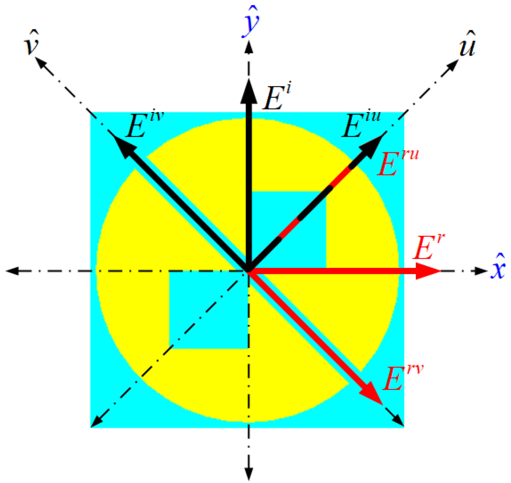
2.2. Geometrical Analysis

The geometric analysis of the metasurface-based polarization converter design suggested in Figure 1 is described in this section to examine the effect of structural changes in the suggested design on the polarization conversion of EM waves. In this section, the suggested design in Figure 1, that is, an efficient polarization converter, is obtained by going through the appropriate evolutionary stages of the design geometry [24]. To this end, the metasurface shape of the suggested design was changed in four stages in various geometries, as given in Figure 3, and the co- and coss-reflection coefficients of the obtained geometries were obtained as shown in Figure 4. The co- and coss-reflection coefficients in Figure 4a–d obtained versus the geometries in Figure 3a–d were examined and evaluated. In Stage 1, a circular structure with a radius of 3.85 mm at the central origin was formed as shown in Figure 3a, and no signs of polarization conversion were observed in the 4–19 GHz frequency range as seen in Figure 4a. In Stage 2, a metasurface cell was created by subtracting a rectangular structure 0.4 mm wide at the central origin, parallel to the v-axis (as seen in Figure 2) from the structure in Stage 1, and the reflection coefficients against this design were obtained as shown in Figure 4b. When Figure 4b is examined, it is seen that two resonances occur at 7.75 and 10.765 GHz frequencies and polarization conversion in C- and X-bands. For the multi-band and broadband conversion, in Stage 3, a metasurface cell was created by subtracting a square with a corner at the origin and a side of 2 mm from the structure in Stage 2, and the reflection coefficients for this design were obtained as shown in Figure 4c. When Figure 4c is examined, it is observed that two resonances occur at 6.88 and 10.27 GHz frequencies, and polarization conversion is observed in the C- and X-bands, but resonance is also observed in the cross-polarization coefficient at 9.145 GHz, and as a result, the frequency range in which polarization occurs is narrowed compared to the previous stage. Finally, in Stage 4, another square with a corner at the origin and a side of 2 mm was removed from the structure in Stage 3 and a symmetrical metasurface structure was created in both the u- and v-axis. In response to this design, the reflection coefficients were obtained as shown in Figure 4d. When Figure 4d is examined, it is seen that three resonances occur at 6.575, 11.125, and 16.925 GHz frequencies, polarization conversion is observed in the C-, X- and Ku-bands, and the co-polarization coefficient is greater than −5 dB in the resonant frequency regions. As a result, it can be said that a multi-band polarization conversion response is obtained by reaching the geometry of the polarization converter design suggested in Figure 1 by going through the stages shown in Figure 3.

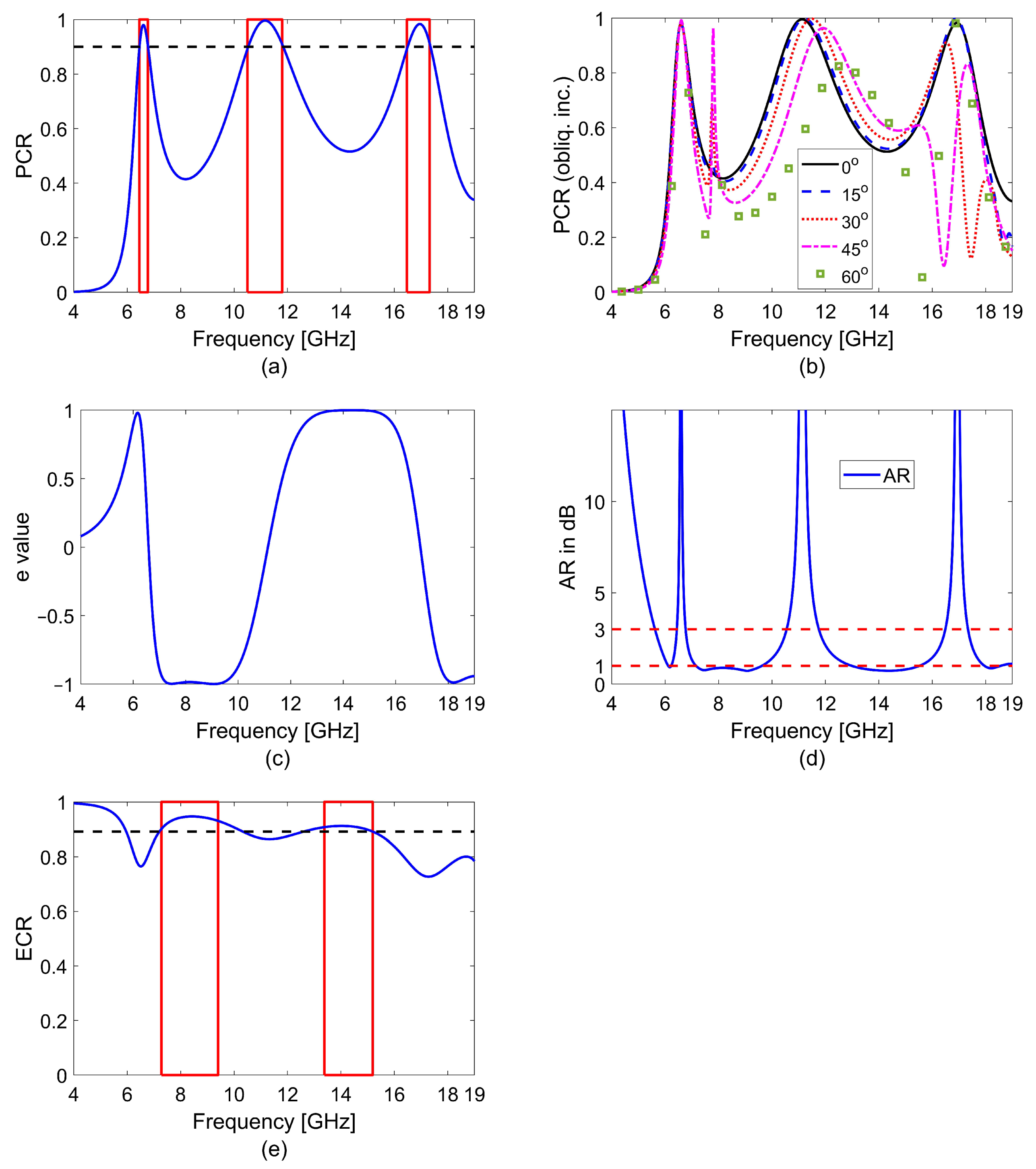
3. Simulation Results

Simulations for the suggested metasurface-based polarization converter design were carried out with a commercial 3D EM simulation program (CST Microwave Studio) in the broader frequency region of 4–19 GHz by choosing a 30 × 30 tetrahedral mesh type. Figure 5a,b shows the simulated co- and cross-polarization coefficients ( R y y and R x y ) for the incoming y-polarized wave under normal incidence of the suggested polarization converter in dB and amplitude, respectively. While Figure 5c shows the phase difference ( Δ ϕ ) between the reflection phases ( ϕ y y and ϕ x y ) and R y y and R x y for co- and cross-polarization under again normal incidence, Figure 5d shows co- and cross-polarization reflection coefficients for four different incidence angles—15 ° , 30 ° , 45 ° , and 60 ° —in addition to normal angle of incidence (0 ° ) for transverse electric (TE) wave. The following points are noted from the results of Figure 5a–d. First, as noted from Figure 5b, the R x y for normal incidence is bigger than 0.85 in three different frequency bands of 6.46–6.78 GHz, 10.52–11.85 GHz, and 16.49–17.37 GHz and R y y has received lower than 0.25 in the same frequency ranges. Secondly, as seen from Figure 5c, ϕ x y has a larger frequency change compared with the frequency change of ϕ y y , meaning that the suggested polarization converter design has different Δ ϕ values with frequency. Thirdly, as seen from Figure 5d, for angles of incidence up to 60 ° , the R x y has not fallen down −8 dB around the three frequency range zones mentioned above. However, with the increase in the oblique incidence, the bandwidth decreased and the performance of the polarization converter deteriorated above 45 ° , as shown in Figure 5d. When the incidence angle increases, the effective impedance of the polarization converter changes [25]. This impedance change affects the interaction of the incident wave with the converter. Due to the reduced interaction, the performance (bandwidth) of the polarization converter partially decreases with an increase in the incidence angle.
To assess the polarization conversion performance of suggested polarization converter, PCR values were calculated from the co- and cross-polarization reflection coefficients at normal and different incidence angles with the help of Equation (1), and the values obtained during 4–19 GHz are given in Figure 6a,b. According to Figure 6a, the PCR value of converter at normal incidence is greater than 90% in three different frequency bands of 6.46–6.78 GHz, 10.52–11.85 GHz, and 16.49–17.37 GHz. This demonstrates that the suggested converter operates fruitfully as an LP converter in the three specified frequency band regions. Figure 6b shows that the PCR value under an incidence angle of incidence up to 45 ° for TE wave is about 90% around the three frequency band regions specified for normal incidence, and for the angle of incidence of 60 ° , the PCR value is about 80% around the frequency region of 6.46–6.78 GHz and 10.52–11.85 GHz. To evaluate the degree of the circularly reflected wave, the e value for normal incidence was calculated with the help of Equation (2) and the obtained values are given in Figure 6c during 4–19 GHz. It is noted from Figure 6c that the converter shows e = −1 in the frequency range of 7.28 and 9.40 GHz; that is, it exhibits linear-to-circular polarization feature with LHCP. The converter has e = +1 in the frequency range of 13.38 and 15.19 GHz, that is, it exhibits linear-to-circular polarization performance with RHCP. In addition, the AR value was calculated from Equation (3) to measure the CP of the incident wave, as given in Figure 6d. In order to determine the operating bandwidth of the CP converter, the frequency range with AR value below 1 dB is considered. Accordingly, the converter suggested from Figure 6d exhibits CP conversion in the frequency ranges 7.28–9.40 GHz and 13.38–15.19 GHz. Finally, to evaluate the CP conversion efficiency of the suggested converter, the ECR value was calculated from Equation (5) as given in Figure 6e. Accordingly, it can be seen from Figure 4e that the efficiency of the CP conversion is above 0.891 in the frequency ranges where the CP conversion takes place (in the frequency ranges where LHCP and RHCP conversion are seen, i.e., 7.28–9.40 GHz and 13.38–15.19 GHz, respectively). This result shows that the suggested design exhibits a high-efficiency CP conversion under normal incidence.
To verify the status of the LP converter, it was specified in Section 2 that | r u u | = | r v v | = 1 and ϕ u u ϕ v v = 180 ° . Figure 7a, the simulated u- and v-axis reflection coefficients sizes of suggested polarization converter shows respectively variation of | r u u | and | r v v | versus frequency. From Figure 7a, | r u u | and | r v v | are not smaller than 0.8 in all frequency band (except for between 6.23–6.78 and 16.42–18.07 GHz). Figure 7b shows the reflection phases ( ϕ u u and ϕ v v ) and the phase difference ( ϕ u u ϕ v v ) along the frequency in the u- and v-axis. It may be seen from Figure 7b that ϕ u u has a sharp phase change at around 11.3 GHz and ϕ v v at 6.80 and 16.55 GHz frequencies. It is also seen that ϕ u u ϕ v v is about ±180 ° along 6.46–6.78, 10.52–11.85, and 16.49–17.37 GHz, about −90 ° (the region where LHCP occurs) along 7.28–9.40 GHz, and +90 ° (the region where RHCP occurs) in the range of 13.38–15.19 GHz. This shows that the suggested polarization converter operates as both LP and CP converter.

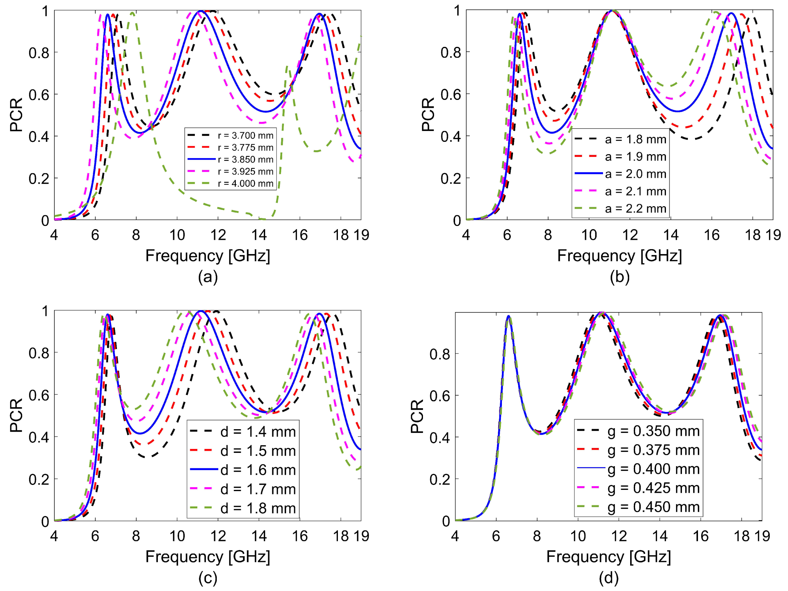
3.1. Dimensional Analysis

A parametric analysis was performed to analyze the effect of the geometric parameters of the suggested polarization converter on the polarization conversion performance and finally to reach the optimized structure shown in Figure 1, namely, the dimensions in Table 1. For this analysis, the r, a, d, and g dimensions in Figure 1 were changed separately, while the other parameters were kept constant. Accordingly, the PCR values for variation in the ranges of r = 3.7–4 mm, a = 1.8–2.2 mm, d = 1.4–1.8 mm, and g = 0.35–0.45 mm for both the widest PCR bandwidth and high performance are shown in Figure 8a–d. In order to obtain the highest polarization conversion and the widest bandwidth in the C-, X-, and Ku-bands from Figure 8a–d, it has been optimized as r = 3.85 mm, a = 2 mm, d = 1.6 mm, and g = 0.4 mm, as previously given in Table 1.

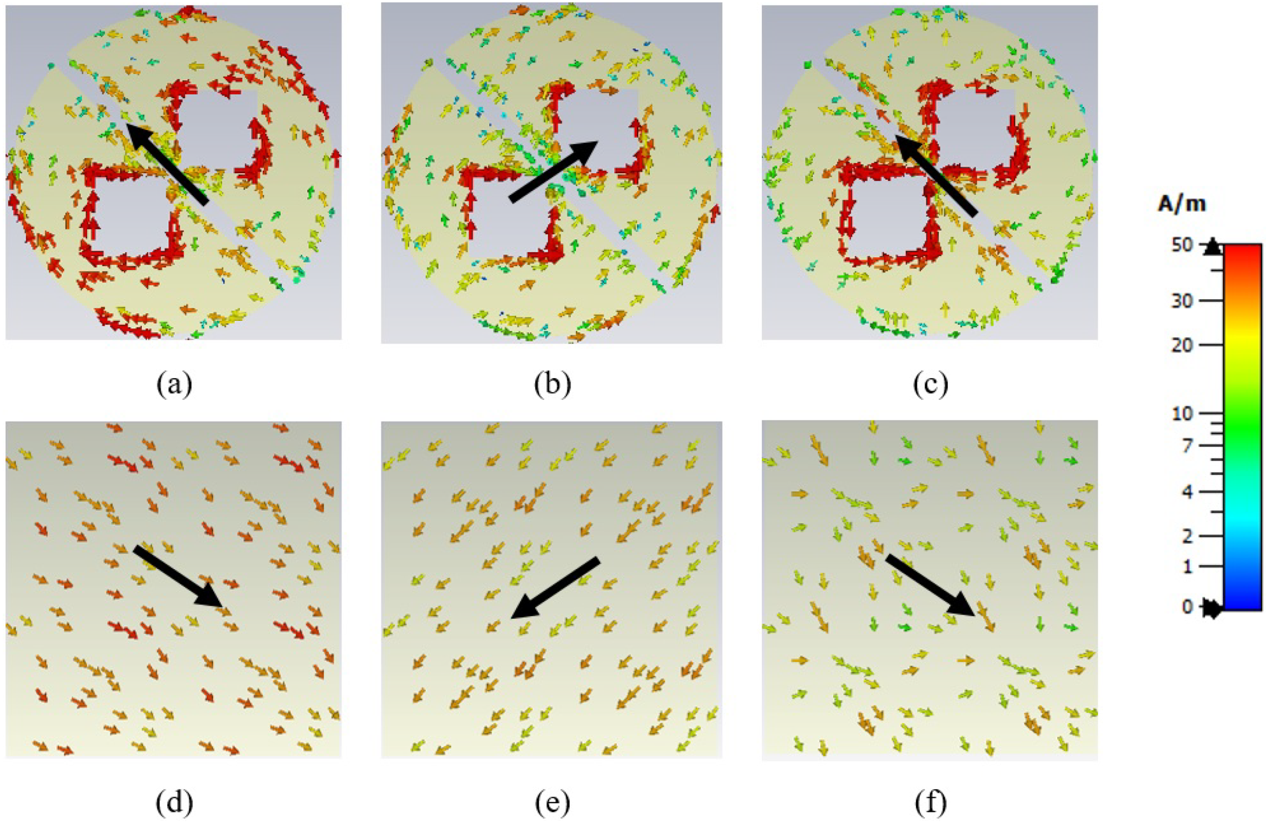
3.2. Surface Current Analysis

Surface current distribution analysis is required to further examine the physical mechanism, performance and efficiency for LP conversion of the suggested polarization converter, and to determine the reason behind the broadband expansion. For the suggested design, the distribution of the surface current density on the metasurface-based resonator and ground show the cause of electric or magnetic resonance.
Figure 9a–f shows the surface current distributions on the ground (Figure 9d–f) and metasurface-based resonator (Figure 9a–c) at resonant frequencies, i.e., 6.575, 11.125, and 16.925 GHz. In addition, in Figure 9, while the head of the arrow shows the direction of the current on the surface, if the current distribution in the metasurface-based resonator and ground are in phase (parallel), electric dipole resonance will occur, otherwise, magnetic resonance will occur if it is out of phase (anti-parallel) [26]. When the surface current distributions of the designed polarization converter in Figure 9a–f are studied, it is seen that the currents in the ground and in the resonator feature opposite directions, that is, the suggested converter design has magnetic resonance at f = 6.575, 11.125, and 16.925 GHz at all three resonance frequencies.

4. Experimental Results

The simulation results of suggested polarization converter were compared and verified in the context of the data obtained with the free-space measurements of the polarization converter produced by the traditional board manufacturing method. Measurements were carried out in the microwave range of frequencies from 8 to 12 GHz (in the X-band) due to limited laboratory facilities. The suggested polarization converter was fabricated as a 25 × 36 (200 mm × 288 mm) unit cell. For free-space measurements, as shown in Figure 10a, Keysight Technologies N9918A (30 kHz–26.5 GHz) brand and model of the vector network analyzer (VNA), two Flann Microwave 16820-PB lens horn antennas operating at X-band with maximum 1.5 voltage standing wave ratio (VSWR) value, and two 1.2 m coaxial cables were used. The distance between the front and rear face apertures of the sample is manually adjusted to approximately 40 cm according to the antenna manual [27]. The horn-lens antennas used in the measurement setup had the capability of focusing EM signals onto the sample (polarization converter). As a result of such feasibility, diffraction effects around the fabricated polarization converter (200 mm × 288 mm) were assumed to be negligible in amount, which was also validated by reflection measurements with similar results implemented with a few pyramidal microwave absorbers positioned next to the converter. The experimental environment in which real-time measurements were made is as shown in Figure 10b. In addition, a widely used and easily implemented calibration technique “thru-reflect-line (TRL)” [28] was employed to remove systematic errors in the measurement system [27,29,30]. The horn antennas used to transmit EM waves to the fabricated metasurface and receive the reflected waves from the metasurface were placed in the horizontal direction for co-polarization measurement and the receiving antenna was placed in the vertical direction for cross-polarization measurement [26]. The measurement setup was arranged in such a manner that co- and cross-polarized reflection coefficients could be comfortably measured with a high accuracy. To this end, a bi-static measurement configuration was implemented [31]. In performing oblique incidence measurements for such a configuration, we positioned the surface of the polarization converter in reference to the aperture of the transmitting antenna in such a manner that the angle between the front surface of the converter and the aperture of the transmitting antenna corresponds to the intended oblique incidence angle. Then, the aperture of the receiving horn antenna was arranged for the same incidence angle (reflected angle due to the Snell’s law of reflection). Due to the physical dimensions of the transmitting and receiving antennas, the minimum incidence angle that could be measured by the constructed setup was around 5 degrees, which in many applications could be considered as the normal incidence case.
The measured co- and cross-reflection coefficients and phases were compared with the simulated results as shown in Figure 11a,b. As seen in Figure 11a,b, it was observed that the measured and simulated results were compatible with each other in the 8–12 GHz frequency range. We think that small frequency shifts and amplitude changes in measured and simulated co- and cross-reflection coefficients and phases arise mainly due to fabrication tolerances, background noises, and/or antenna misalignment [32]. Although we present measurement results of co- and cross-reflection coefficients and phases at X-band only (due to insufficient facilities in the laboratory), we expect good agreement between measured and simulated coefficients at C- and Ku-bands.

5. Comparison

As shown in Table 2, the performance of the suggested polarization converter was compared with the performance of other converters in the literature. For this purpose, the suggested polarization converter was compared with other polarization converters in the literature in terms of bandwidth, polarization type, angle, thickness, and material type as given in Table 2. According to this comparison, the suggested polarization converter provides both circular and linear polarization conversion according to reference [33,34,35,36]. The suggested polarization converter was compared with other studies according to the oblique angle sensitivity and it was found that oblique angle performance was better than references [35,36,37] and it was also competitive with the references [33,34,38] (the oblique angle performances are the same as the suggested polarization converter). In addition, the suggested polarization converter was compared in terms of thickness with reference [33,34,35,36,37,38], and it was noted that the suggested study (1.6 mm substrate thickness (0.034 λ )) is thinner than all other referenced studies. In terms of the type of substrate used, the suggested study is easily available and inexpensive compared with other studies [34,36]. Finally, the suggested polarization converter shows both LP and CP conversion properties in C-, X-, and Ku-bands, according to other studies compared.

6. Conclusions

In this study, the design of broadband, ultra-thin, and multi-purpose metasurface polarization converter for C-, X-, and Ku-band applications is presented. The suggested design with the metasurface principle in the form of a metallic-dielectric-metallic arrangement as a single layer has both LP and CP converter features. In three different frequency bands of 6.46–6.78 GHz, 10.52–11.85 GHz, and 16.49–17.37 GHz for suggested design in normal incidence case, PCR is more than 90% and shows linear-to-linear polarization performance, while it shows linear-to-circular polarization performance with LHCP feature in the 7.28 and 9.40 GHz frequency range and RHCP feature in the 13.38 and 15.19 GHz frequency range. It is also seen that the PCR value of suggested converter is around 90% for the oblique incidence case with angles over 0–45 ° . Accordingly, the suggested metasurface-based design with its angular stability, performance, and efficiency has potential applications in sensor applications, EM measurements, antenna design, and invisibility technology.

Funding

This research received no external funding.

Institutional Review Board Statement

Not applicable.

Informed Consent Statement

Not applicable.

Data Availability Statement

Not applicable.

Conflicts of Interest

The author declares no conflict of interest.

References

  1. Khan, M.I.; Khalid, Z.; Tahir, F.A. Linear and circular-polarization conversion in X-band using anisotropic metasurface. Sci. Rep. 2019, 9, 4552. [Google Scholar] [CrossRef] [PubMed]
  2. Ozturk, G. Ultra-thin, wide-angle and bandwidth-enhanced linear and circular metasurface-based reflection-type polarization converter at X-band microwave frequency. J. Electromagn. Waves Appl. 2022, 36, 1423–1435. [Google Scholar] [CrossRef]
  3. Nguyen, T.K.T.; Nguyen, T.M.; Nguyen, H.Q.; Cao, T.N.; Le, D.T.; Bui, X.K.; Bui, S.T.; Truong, C.L.; Vu, D.L.; Nguyen, T.Q.H. Simple design of efficient broadband multifunctional polarization converter for X-band applications. Sci. Rep. 2021, 11, 2032. [Google Scholar] [CrossRef] [PubMed]
  4. Huang, X.J.; Yang, H.L.; Zhang, D.H.; Luo, Y. Ultrathin dual-band metasurface polarization converter. IEEE Trans. Antennas Propag. 2019, 67, 4636–4641. [Google Scholar] [CrossRef]
  5. Rotshild, D.; Abramovich, A. Ultra-wideband reconfigurable X-band and Ku-band metasurface beam-steerable reflector for satellite communications. Electronics 2021, 10, 2165. [Google Scholar] [CrossRef]
  6. Dong, J.; Ding, C.; Mo, J.J. A low-profile wideband linear-to-circular polarization conversion slot antenna using metasurface. Materials 2020, 13, 1164. [Google Scholar] [CrossRef]
  7. Martinez-de-Rioja, E.; Martinez-de-Rioja, D.; López-Sáez, R.; Linares, I.; Encinar, J.A. High-efficiency polarizer reflectarray antennas for data transmission links from a CubeSat. Electronics 2021, 10, 1802. [Google Scholar] [CrossRef]
  8. Shukoor, M.A.; Dey, S. Broadband linear-cross reflective type polarization converter for X and Ku-band applications. In Proceedings of the 2020 International Symposium on Antennas & Propagation (APSYM), Cochin, India, 14–16 December 2020; p. 20466548. [Google Scholar]
  9. Dutta, R.; Ghosh, J.; Yang, Z.B.; Zhang, X.Q. Multi-band multi-functional metasurface-based reflective polarization converter for linear and circular polarizations. IEEE Access 2021, 9, 152738–152748. [Google Scholar] [CrossRef]
  10. Mutlu, M.; Ozbay, E. A transparent 90 polarization rotator by combining chirality and electromagnetic wave tunneling. Appl. Phys. Lett. 2012, 100, 051909. [Google Scholar] [CrossRef]
  11. Pouyanfar, N.; Nourinia, J.; Ghobadi, C. Multiband and multifunctional polarization converter using an asymmetric metasurface. Sci. Rep. 2021, 11, 9306. [Google Scholar] [CrossRef]
  12. Baghel, A.K.; Kulkarni, S.S.; Nayak, S.K. Linear-to-cross-polarization transmission converter using ultrathin and smaller periodicity metasurface. IEEE Antennas Wirel. Propag. Lett. 2019, 18, 1433–1437. [Google Scholar] [CrossRef]
  13. Xu, J.; Li, R.Q.; Wang, S.Y.; Han, T.C. Ultra-broadband linear polarization converter based on anisotropic metasurface. Opt. Express 2018, 26, 26235–26241. [Google Scholar] [CrossRef]
  14. Yang, W.C.; Meng, Q.; Che, W.Q.; Gu, L.Z.; Xue, Q. Low-profile wideband dual-circularly polarized metasurface antenna array with large beamwidth. IEEE Antennas Wirel. Propag. Lett. 2018, 17, 1613–1616. [Google Scholar] [CrossRef]
  15. Baena, J.D.; Glybovski, S.B.; del Risco, J.P.; Slobozhanyuk, A.P.; Belov, P.A. Broadband and thin linear-to-circular polarizers based on self-complementary zigzag metasurfaces. IEEE Trans. Antennas Propag. 2017, 65, 4124–4133. [Google Scholar] [CrossRef]
  16. Karamirad, M.; Ghobadi, C.; Nourinia, J. Metasurfaces for wideband and efficient polarization rotation. IEEE Trans. Antennas Propag. 2021, 69, 1799–1804. [Google Scholar] [CrossRef]
  17. Lin, B.Q.; Huang, W.Z.; Yang, Y.S.; Guo, J.X.; Lv, L.T.; Zhang, J.T. An ultra-wideband polarization conversion metasurface for RCS reduction. J. Electromagn. Waves Appl. 2022, 36, 597–606. [Google Scholar] [CrossRef]
  18. Loncǎr, J.; Grbic, A.; Hrabar, S. A reflective polarization converting metasurface at X-band frequencies. IEEE Trans. Antennas Propag. 2018, 66, 3213–3218. [Google Scholar] [CrossRef]
  19. Wang, M.J.; Zhai, Z.Z. Wide-angle circular polarization converter based on a metasurface of Z-shaped unit cells. Front. Phys. 2020, 8, 527394. [Google Scholar] [CrossRef]
  20. Jiang, Y.N.; Zhao, H.P.; Wang, L.; Wang, J.; Cao, W.P.; Wang, Y.Y. Broadband linear-to-circular polarization converter based on phosphorene metamaterial. Opt. Mater. Express 2019, 9, 2088–2097. [Google Scholar] [CrossRef]
  21. Lin, B.Q.; Da, X.Y.; Wu, J.L.; Li, W.; Fang, Y.W.; Zhu, Z.H. Ultra-wideband and high-efficiency cross polarization converter based on anisotropic metasurface. Microwaves Opt. Technol. Lett. (MOP) 2016, 58, 2402–2405. [Google Scholar] [CrossRef]
  22. Ran, Y.Z.; Shi, L.H.; Wang, J.B.; Wang, S.B.; Wang, G.M.; Liang, J.G. Ultra-wideband linear-to-circular polarization with ellipse-shaped metasurfaces. Opt. Commun. 2019, 451, 124–128. [Google Scholar] [CrossRef]
  23. Jiang, Y.N.; Wang, L.; Wang, J.; Akwuruoha, C.N.; Cao, W.P. Ultra-wideband high-efficiency reflective linear-to-circular polarization converter based on metasurface at terahertz frequencies. Opt. Express 2017, 25, 27616–27623. [Google Scholar] [CrossRef] [PubMed]
  24. Khan, B.; Kamal, B.; Ullah, S.; Abdullah; Ali, H.; Ullah, R. Asymmetric polarization converting metasurface for microwave applications. Opt. Mater. Express 2022, 12, 3403–3415. [Google Scholar] [CrossRef]
  25. Ozturk, G.; Hasar, U.C.; Bute, M.; Ertugrul, M. Determination of constitutive parameters of strong-coupled bianisotropic metamaterials using oblique incidence scattering parameters. IEEE Trans. Antennas Propag. 2021, 69, 918–927. [Google Scholar] [CrossRef]
  26. Khan, B.; Kamal, B.; Ullah, S.; Khan, I.; Shah, J.A.; Chen, J.D. Design and experimental analysis of dual-band polarization converting metasurface for microwave applications. Sci. Rep. 2020, 10, 15393. [Google Scholar] [CrossRef]
  27. Hasar, U.C.; Kaya, Y.; Ozturk, H.; Izginli, M.; Ertugrul, M.; Barroso, J.J.; Ramahi, O.M. Improved method for permittivity determination of dielectric samples by free-space measurements. IEEE Trans. Instrum. Meas. 2022, 71, 6002108. [Google Scholar] [CrossRef]
  28. Engen, G.F.; Hoer, C.A. Thru-reflect-line: An improved technique for calibrating the dual six-port automatic network analyzer. IEEE Trans. Microw. Theory Tech. 1979, 27, 987–993. [Google Scholar] [CrossRef]
  29. Hasar, U.C.; Ozturk, G.; Kaya, Y.; Ertugrul, M. Calibration-free time-domain free-space permittivity extraction technique. IEEE Trans. Antennas Propag. 2022, 70, 1565–1568. [Google Scholar] [CrossRef]
  30. Hasar, U.C.; Kaya, Y.; Ozturk, H.; Izginli, M.; Barroso, J.J.; Ramahi, O.M.; Ertugrul, M. Complex permittivity and thickness evaluation of low-loss dielectrics from uncalibrated free-space time-domain measurements. IEEE Trans. Geosci. Remote Sens. 2022, 60, 4702410. [Google Scholar] [CrossRef]
  31. Umari, M.H.; Ghodgaonkar, D.K.; Varadan, V.V.; Varadan, V.K. A free-space bistatic calibration technique for the measurement of parallel and perpendicular reflection coefficients of planar samples. IEEE Trans. Instrum. Meas. 1991, 40, 19–24. [Google Scholar] [CrossRef]
  32. Hasar, U.C.; Muratoglu, A.; Bute, M.; Barroso, J.J.; Ertugrul, M. Effective constitutive parameters retrieval method for bianisotropic metamaterials using waveguide measurements. IEEE Trans. Microw. Theory Tech. 2017, 65, 1488–1497. [Google Scholar] [CrossRef]
  33. Nguyen, T.Q.H.; Nguyen, T.K.T.; Nguyen, T.Q.M.; Cao, T.N.; Phan, H.L.; Luong, N.M.; Le, D.T.; Bui, X.K.; Truong, C.L.; Vu, D.L. Simple design of a wideband and wide-angle reflective linear polarization converter based on crescent-shaped metamaterial for Ku-band applications. Opt. Commun. 2021, 486, 126773. [Google Scholar] [CrossRef]
  34. Yang, X.K.; Ding, Z.; Zhang, Z.P. Broadband linear polarization conversion across complete Ku band based on ultrathin metasurface. AEU Int. J. Electron. Commun. 2021, 138, 153884. [Google Scholar] [CrossRef]
  35. Zheng, Q.; Guo, C.J.; Li, H.X.; Ding, J. Broadband radar cross-section reduction using polarization conversion metasurface. Int. J. Microw. Wirel. Technol. 2018, 10, 197–206. [Google Scholar] [CrossRef]
  36. Kamal, B.; Chen, J.D.; Yin, Y.Z.; Ren, J.; Ullah, S.; Ali, U. Design and experimental analysis of dual-band polarization converting metasurface. IEEE Antennas Wirel. Propag. Lett. 2021, 20, 1409–1413. [Google Scholar] [CrossRef]
  37. Zheng, Q.; Guo, C.J.; Vandenbosch, G.A.E.; Yuan, P.L.; Ding, J. Dual-broadband highly efficient reflective multi-polarisation converter based on multi-order plasmon resonant metasurface. IET Microwaves Antennas Propag. 2020, 14, 967–972. [Google Scholar] [CrossRef]
  38. Zheng, Q.; Guo, C.J.; Ding, J. Wideband metasurface-based reflective polarization converter for linear-to-linear and linear-to-circular polarization conversion. IEEE Antennas Wirel. Propag. Lett. 2018, 17, 1459–1463. [Google Scholar] [CrossRef]
Figure 1. (a) Front view and (b) side view of suggested converter design.
Symmetry 15 00442 g001
Figure 2. The principle of operation of the polarization converter: Analysis of the electric field reflected in the x direction using the u v plane for an electric field coming from the y direction.
Symmetry 15 00442 g002
Figure 3. The stages involved in the geometric design of the suggested polarization converter: (a) Circular structure (Stage 1), (b) metasurface unit cell created by removing a rectangular patch from the circular structure (Stage 2), (c) the metasurface unit cell created by removing a rectangular and a square patch from the circular structure (Stage 3), and (d) the metasurface unit cell created by removing one rectangular and two square patches from the circular structure (Stage 4: The suggested polarization converter geometry in Figure 1).
Symmetry 15 00442 g003
Figure 4. Comparison of co- and cross-reflection coefficients ( R y y and R x y ) by changing the geometry of an efficient polarization converter design suggested in Figure 1: (a) Stage 1, (b) Stage 2, (c) Stage 3, and (d) Stage 4.
Symmetry 15 00442 g004
Figure 5. For simulated co- and cross-polarization of the suggested polarization converter (a) in dB and (b) linear reflection coefficients, (c) ϕ y y and ϕ x y phases and Δ ϕ phase difference, and (d) reflection coefficients for different angles of incidence.
Symmetry 15 00442 g005
Figure 6. Calculated values from the simulated co- and cross-polarization reflection coefficients ( R y y and R x y ) for suggested polarization converter: (a) PCR value for normal incidence and (b) PCR values for four different angles of incidence (15 ° , 30 ° , 45 ° , and 60 ° ) in addition to the normal incidence, (c) e value for normal incidence, (d) AR value for normal incidence, and (e) ECR value for normal incidence.
Symmetry 15 00442 g006
Figure 7. The suggested polarization converter (a) complex magnitudes of reflection coefficients on the simulated u- and v-axis ( | r u u | and | r v v | ) and (b) reflection phases ( ϕ u u and ϕ v v ) and phase difference ( ϕ u u ϕ v v ).
Symmetry 15 00442 g007
Figure 8. Variation of PCR for various dimension parameters of the suggested polarization converter: (a) r = 3.7–4 mm, (b) a = 1.8–2.2 mm, (c) d = 1.4–1.8 mm, and (d) g = 0.35–0.45 mm.
Symmetry 15 00442 g008
Figure 9. Surface current distributions on the ground and metasurface-based resonator in all resonance frequencies for LP conversion: (a,d) 6.575 GHz, (b,e) 11.125 GHz, and (c,f) 16.925 GHz.
Symmetry 15 00442 g009
Figure 10. (a) The measurement setup scenario and (b) image of experimental measurement setup for free-space measurement.
Symmetry 15 00442 g010
Figure 11. Comparison of the measured and simulated co- and cross-reflection coefficients and phases for suggested polarization converter: (a) Simulated and measured co- and cross-reflection coefficients, respectively ( R y y ( Sim . ) - R y y ( Meas . ) and R x y ( Sim . ) - R x y ( Meas . ) ) and (b) measured and simulated co- and cross-reflection phases, respectively ( ϕ y y ( Sim . ) - ϕ y y ( Meas . ) and ϕ x y ( Sim . ) - ϕ x y ( Meas . ) ).
Symmetry 15 00442 g011
Table 1. Dimensions (mm) of the suggested polarization converter.
Lragdt
83.8520.41.60.035
Table 2. Comparison of the suggested polarization converter and polarization converters in the studies in [33,34,35,36,37,38].
StudyOperation
Bandwidth
[GHz]
ConversionAngleSubstrate
Thickness
Substrate
Type
PCR
Efficiency
[33]12–18LP-LP45 ° 1.6 mm
(0.064 λ )
FR-490%
[34]11.90–18.05LP-LP45 ° 1.5 mm
(0.059 λ )
F4-B90%
[35]9.24–17.64LP-LP30 ° 2 mm
(0.061 λ )
FR-490%
[36]5.4–9.0
14.6–16.1
LP-LPNA3.2 mm
(0.057 λ )
RO400393%
[37]7.74–14.44
14.95–17.35
LP-LP
LP-CP
30 ° 3 mm
(0.077 λ )
FR-490%
[38]6.53–12.07
13.7–15.6
LP-LP
LP-CP
45 ° 3.1 mm
(0.067 λ )
FR-488%
The Suggested
Study
6.46–6.78
7.28–9.40
10.52–11.85
13.38–15.19
16.49–17.37
LP-LP
LP-CP
LP-LP
LP-CP
LP-LP
45 ° 1.6 mm
(0.034 λ )
FR-490%
Disclaimer/Publisher’s Note: The statements, opinions and data contained in all publications are solely those of the individual author(s) and contributor(s) and not of MDPI and/or the editor(s). MDPI and/or the editor(s) disclaim responsibility for any injury to people or property resulting from any ideas, methods, instructions or products referred to in the content.

