1. Introduction
During the last decades, researchers have especially focused their attention on defining mathematical and calculation models for solving the problem of modern laminated composite structures. It is generally known that these structures are manufactured by stacking laminae made of modern materials, containing parallel continuous fibers carrying load in one direction defined by the angle-ply orientation θ. Fibers can be made of one type of material and incorporated into the matrix of another material.
In addition to more favorable characteristics related to weight reduction, higher load-bearing capacity, and resistance, modern laminated composite structures also have disadvantages, which, among others, include the occurrence of cracks and gaps at the lamina connections. The heterogeneity of the anisotropic composition of the laminated structure leads to the occurrence of a large number of irregularities at the plate level, at the lamina level, as well as at the micro level of the fiber/matrix material. These irregularities or imperfections can occur in different manufacture stages, in embedding, and during exploitation of the laminated structure.
At the lamina level, composites often contain the concentration of stress near material or geometric imperfections, leading to their increase and propagation. Imperfections at the lamina connections greatly affect the load-bearing capacity of the laminated composite structures, especially due to the significantly lower shear stiffness and load-bearing capacity perpendicular to the plane of the laminae, in relation to the tensile load-bearing capacity.
A thin layer of binding material connects adjacent layers in the laminated structure. This layer transfers influences, displacements, and forces from one lamina to another. When this connection weakens or does not exist, imperfections in the form of separation of connected laminae, known as delamination, occur. Delamination, its increase, and development during exploitation are some of the important parameters affecting the load-bearing capacity and design working life of a laminated structure. Stress concentration and local instability occur at the delamination points. After embedding, the influence of the exploitation load leads to the redistribution of internal stresses, which causes delamination to increase. The increase and further propagation of delamination can result in the loss of the load-bearing capacity and the fracture of the laminated structure. Delamination is known to be the most common type of imperfection in laminated structures, and it limits their load-bearing capacity and affects their service life. These are the reasons why structural engineers should include the occurrence of delamination, i.e., imperfections at the laminae connections, in their calculations.
Depending on the position, there are two basic delamination types: internal delamination located deep within the cross-section, and delamination located close to the surface. Delamination located near the surface of the laminated composite is a specific type of damage, as its behavior is usually associated with the buckling of the surface laminae. Therefore, to study this delamination type, it is necessary to consider the stability of the lamina from the perspective of elastic stability theory. This is especially important for components of structures loaded in the plane. Multiple “gaps” at laminae connections also occur, which is why their influence on the overall load-bearing capacity and safety of the laminated structure is of crucial importance.
Laminated structures, in which delamination has occurred, have reduced load-bearing capacity and stiffness. For this reason, when analyzing laminated structures, involving plates, it is necessary to adopt such calculation models that include the impact of delamination on the load-bearing capacity.
Every day, we witness the increasing application of modern composite materials in various fields of industry. Therefore, it is of great importance to develop new, modern theories that can encompass a number of problems, including the problems of occurrence and development of delamination. Only a small part of the extensive literature dealing with the behavior of laminated structures is given in the references [
1,
2,
3,
4,
5,
6,
7,
8,
9,
10,
11,
12,
13,
14,
15,
16,
17,
18,
19,
20,
21,
22,
23,
24,
25,
26,
27,
28,
29,
30,
31,
32,
33,
34,
35,
36,
37,
38]. Modern methods of analysis are based on equivalent single-layer theories, zig-zag theories, and layerwise theories, within which a large number of mathematical models and calculation procedures have been developed.
Laminated composite plates belong to the group of laminated structures in which the third dimension, height, is smaller than the other two dimensions, the width and length of the plate. Unlike single-layer classical and shear theories of laminated plates, layerwise theories transfer assumptions from the level of the laminated plate to the level of the lamina, because of which it is possible to include local defects occurring at the lamina level in mathematical models. Layerwise theories are recommended [
1,
2,
3,
4,
5,
6,
7,
8,
9,
10,
11] for moderately thick and thick laminated plates with anisotropic behavior, for which it is necessary to define the real interlaminar stresses and deformation, as well as in cases when it is necessary to include imperfections of geometry and materials in the calculation.
Based on mathematical models of laminated plate theories, a large number of calculation models, analytical and numerical procedures for defining the stress–strain state in laminated plates without delamination have been developed. This article is based on the layerwise theory developed by J. N. Reddy et al. and known as the generalized laminated plate theory (GLPT) [
6,
7,
8,
9,
10]. GLPT is a general layerwise theory that considers a layer by a layer, by means of which it is possible to include delamination at laminae connections in the calculation (variable kinematic model) [
11].
In recent years the professional and scientific public is especially interested in defining numerical models of discrete analysis, including the increase and propagation of delamination within the cross-section. Imperfections of layered structures that occur during production due to the lack of a matrix, inadequate hardening, trapped air, and other elements, which leads to the “emptiness” that causes the local separation of layers, are the topic of this paper. During exploitation, due to a static or dynamic load, the separation between layers of a layered structure may also occur. These defects, regardless of how they occur, significantly reduce the load-bearing capacity of the layered structure, which is shown in this paper.
In order to understand the problem of delamination, a large number of researchers have developed and proposed numerical and experimental procedures based on various available and modified theories. From the extensive literature, the authors have relied on a small part of the literature resources [
39,
40,
41,
42,
43,
44,
45,
46,
47,
48,
49]. These literature resources consider delamination with a determined geometry, and an analysis is carried out by varying certain parameters based on the models of single-layer or layerwise theories. It is well known that in numerical methods and programs (existing commercial software) based on numerical models, discretization errors and interpolation errors occur, which leads to a series of open questions that need to be resolved in the numerical calculation procedure. It is also widely known that numerical solutions can be checked by comparing them with analytical solutions; of course, if they exist and can be reached. Experimental research, as a significant segment of the research into the problem of delamination, is limited to the conditions of an experiment. Reaching comprehensive conclusions experimentally requires testing a great number of samples with different input data. Numerical and experimental research contributes to a better understanding of the problem of delamination, its occurrence, growth, development, and propagation.
However, as far as the authors know, there is no analytical approach for including delamination in a calculation based on layer theory. With this in mind, this article represents a special contribution, because it offers a new approach to determining an analytical solution to the problem of bending the plates, by applying the layerwise theory when the cross-section contains a “gap” in the bond between two layers. The considered delamination has a local character and occurs in the production process (for example, trapped air at a certain point of the bond between two layers).
The new approach of the embedding of delamination is based on the calculation procedure of the layer theory, which transfers considerations from the level of the laminated plate to the level of the lamina. This calculation procedure determines the value of “sliding” at the point where there is no bond between two layers, i.e., the value of the “separation” or delamination in the plane (x, y) is determined. A mathematical model of the layer theory has been constructed for situations where the elongation perpendicular to the middle plane of the plate is zero, whereby equations of these theories are solved analytically, in a closed form.
This new approach, of defining the zero stress and strain of the cross-section with internal delamination, can be further improved, expanded, or supplemented by including new members related to the final geometry of the delamination in the mathematical model, in cases where the gap is not local and/or involving nonlinear effects dealing with the growth, development, and propagation of delamination. This will be the object of future research.
Given that the reported new calculation procedure involving internal local delamination is analytical and automated by the development of a program code, it can be used as a comparable one for numerical methods and procedures.
2. Mathematical Model for Laminated Plates with Delamination
2.1. Theoretical Background
Mathematical models for the problems of the bending of laminated composite plates can be constructed through differential or integral equations (strong form or weak form), while satisfying the boundary conditions on the contour. Methods for solving the equations of problems can be analytical, numerical, or approximate, as well as mixed methods obtained using a combination of those mentioned. An analytical solution, or a solution in a closed form, predicts the state of stresses and deformation, in the form of a function for the assumptions of the chosen theory, and this can be defined only for the simplest problems, simple geometry of the laminated composite, and simple conditions of support. For laminated plates, primary unknowns are assumed in the form of series of trigonometric functions. For bending problems of rectangular plates, Navier’s solution is used (solution by double trigonometric series) or Levy’s solution (solution by single trigonometric series), depending on the boundary conditions that need to be met. The most frequently used numerical methods for the calculation of laminated plates are the finite differences method and the finite elements method, as well as other available methods based on the discretization of the problem under consideration. Analytical results are usually used as a benchmark for numerical and other solutions obtained by discretization of the considered structure. Among the approximate methods, the most commonly used are the Ritz method, Galerkin method, and Kantorović method.
The general deformation of laminated rectangular plates is often defined by complicated connections between the axial deformation, bending, and shear, because of which, this paper uses a combination of analytical and approximate methods for solving mathematical equations of elasticity layerwise theory.
To define a new cross-sectional calculation procedure with delamination, a mathematical model has been developed. It is based on Reddy’s partial layerwise plate theory (PLPT), being a special case of GLPT. In this paper, equations of equilibrium, derived by applying the principle of virtual displacements, are solved analytically, using a double series and discretization of the cross-section with the nodes at laminae ends. The presented calculation procedure is automated through drawing up the original Fortran program code, which is an upgrade of the program designed for cross-sections of the laminated plates without delamination [
14,
15].
2.2. Displacements, Strains, and Stresses
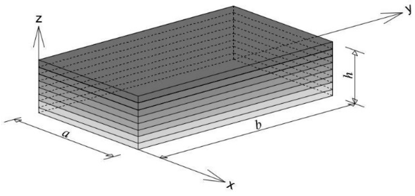
A simple supported laminated plate with thickness
h and dimension
a ×
b, containing laminae whose fibers are arbitrarily oriented is considered,
Figure 1. Considerations are carried out in the rectangular Cartesian coordinate system, and for the cross-section without delamination, the following assumptions are accepted:
At the lamina level, the material is elastic and orthotropic. The consequence of this assumption is a linear stress–strain relationship at the lamina level;
Elongation perpendicular to the plane of the plate (x, y) is neglected εzz = 0. As a consequence of this assumption, the strain tensor in the considered system (x, y, z) has five members, while the deflection w is the function of the coordinates x and y;
Discretization of the cross-section through thickness is performed using 1D elements, with nodes at the laminae ends. As a consequence of this assumption, the primary unknowns are the component displacements at points defined by the thickness of the cross-section, being the function of the coordinates of these points;
Delamination is located at the connection of two laminae. At the delamination point, there is no connection between the two laminae.
In accordance with the above-mentioned assumptions, for the case of a cross-section without delamination, a displacement field in the considered layer theory is assumed in the following form,
Figure 2:
where
u(
x,
y),
v(
x,
y) and
w(
x,
y)—component displacements of the middle plane of the plate,
U(
x,
y,
z) and
V(
x,
y,
z)—additional displacements through the thickness of the plate.
Additional displacements are determined as the sum of the multiplications of the unknown nodal displacements
uJ(
x,
y) or
vJ(
x,
y), and one dimensional linear interpolation functions
ψJ(
z) are defined along two connected laminae:
n—the total number of nodes through the thickness for the cross-section without delamination,
J—the mark for the node.
Based on the above, it can be concluded that, for a cross-section without delamination, the total number of nodes through the thickness of the cross-section is greater for one than the total number of laminae n = N + 1. N is the mark for the total number of laminae of the laminated plate.
For a cross-section containing delamination, the displacement change through the thickness of the cross-section is different from the displacement change given in
Figure 2b. A cross-section with a single internal delamination located between the laminae marked as (
j − 1) and (
j) is shown in
Figure 3a, while
Figure 3b shows the assumed displacement change through the thickness of the cross-section, for the x direction. The displacement change through the thickness in the y direction is described in an equivalent way. At the delamination point, there is a sudden increase, i.e., a sudden change in displacement.
For a section with delamination, the number of nodes throughout the thickness depends on the number of places with delamination. If the cross-section has
md delaminations, the total number of nodes through the thickness of the cross-section, in which the displacement values
uJ(
x,
y) and
vJ(
x,
y) are calculated, is determined by applying the following equation:
In a case when md = 1, the total number of nodes through the thickness of the cross-section, in which the basic unknowns are calculated, is nd = N + 2.
In the general case, if it is assumed that there is delamination between the laminae marked as (
j − 1) and
(j), then the interpolation functions are adopted in the following form:
where
J is the mark for the node.
Figure 4 shows a laminated plate with five laminae and delamination between the second and third laminae. At the delamination point, there is no physical connection between the laminae (node marks 3 and 4), and this is why the interpolation functions along the laminae marked as 2 and 3 are shown by two interpolation functions
ψ31 and
ψ42.
In accordance with the assumptions, and based on relations (1) and (2), for the cross-section with delamination, the displacements are determined as follows:
In this case, the equations of the displacement and deformation relation can be shown in the following form:
Based on the previous equation and the first assumption, for every lamina
j, the connections between stress and displacement are shown by the relations:
In the previous relation are the transformed stiffnesses of the j-th lamina. These values depend on the material characteristics and the lamina orientation θ.
2.3. Equations of Bending and Solutions
Cross-section forces are calculated as stress integrals. By integrating relations (7) the laminated plate forces with delamination are obtained:
where
Nx, Ny, Nxy, Qx, and Qy are forces in the middle plane of the plate;
NxJ, NyJ, NxyJ, QxJ, and QyJ are forces in the node J of the cross-section with delamination;
Aij, BijJ, and DijJI are the stiffness of the laminated plate with delamination.
By integrating the products of stiffness, interpolation functions, and derivatives of interpolation functions along laminae 1, …,
N, stiffness of the laminated plate,
Aij,
BijJ, and
DijJI is obtained out of the following relations:
The occurrence of delamination at the laminae connections causes a change of stiffness Aij, BijJ, and DijJI of the laminated composite, when compared to the values calculated for the same cross-section without delamination.
Based on the principle of stationary potential energy, the equations of equilibrium are obtained. The most simplified form of these equations is obtained in case the laminae are cross-ply, i.e., when the laminae are with the following angles of orientation: 0° and 90°. In that case, according to the relations (10) and stiffness
A16 =
A26 =
A45 =
B16J =
B26J =
B45J =
D16JI =
D26JI =
D45JI, they are equal to zero, which is why the equations of equilibrium are formulated as follows:
where
q is the transverse load.
System (3 + 2nd) of the differential Equation (11), i.e., 3 + 2(N + 2), in the case where there is one delamination in the cross-section, with the same number of basic unknowns, makes a complete system of equations, for which it is possible to find an unambiguous solution.
A solution to the system of Equation (11) can be obtained by using analytical and numerical methods, while satisfying the boundary conditions.
In this paper, solutions have been determined with the adopted discretization of laminae through the cross-section, with 1D elements and nodes at laminae ends. Due to the complexity of the procedure, the solutions to the equations of equilibrium of bending the laminated plate with delamination, on the grounds of the hereby proposed new procedure of calculating, have been determined for simply supported laminated plates with one delamination through the cross-section. The procedure has been automated, and it is possible to simply upgrade it, in case of having a greater number of delaminations.
On the basis of the foregoing considerations, the primary unknowns are assumed in the form of double trigonometric functions:
that satisfy the boundary conditions for simply supported plates:
Through determining the derivative of the functions of relations (12) and by putting it into the system of Equation (11) the system of 3 + 2(
N + 2) algebraic equations is obtained as follows:
with as many unknown coefficients
Xmn,
Ymn,
Wmn,
RmnJ and
SmnJ, where
J = 1, …,
nd. Submatrices of the coefficients’ matrix of conditional equations [
K], [
Kj], and [
Kji] have been determined in accordance with the procedure outlined in the literature [
14], with a difference that relates to the change of the entire number of nodes and the change of the interpolation cross-section with delamination.
The transverse load
q is also assumed in the form of double trigonometric functions:
where
Qmn are the coefficients depending on the type of load, and which are determined by integration.
For the two types of loads being dealt with in this paper, the following is obtained through integration:
After determining the unknown coefficients Xmn, Ymn, Wmn, RmnJ, and SmnJ for each pair (m, n), and for each node J = 1, …, nd, by applying relations (12) and (5), the components of displacement of arbitrary points with coordinates (x, y, z) are determined.
Deformations and stresses are calculated according to the Equations (6) and (7). Shear stresses in the planes (
x,
z) and (
y,
z) are calculated by the specific calculation procedure devised by the author of this paper and are presented in detail in the bibliographic references [
12] and adjusted to new boundary conditions at the place of delamination.
The previously shown new calculation procedure of displacement and stress for the cross-section with one internal delamination is automated by creating its own program.
3. Numerical Examples and Results
Based on the above-mentioned new analytical approach to the embedding of delamination, based on the layerwise theory, the program DELACOP (delaminations of laminated composite plates) was written in the programming language Fortran.
The input file INP.dat for this program consists of five groups of data. The first group contains the total number of laminae N, number of nodes in the plane (x, y) in which the values of variables are to be calculated, the total number of nodes through the thickness of the plate for the cross-section with delamination nd, as well as the length and the width of the plate. The second group of data includes material characteristic for each of these laminae j = 1, …, N, whereas the third group is composed of data at angles of the orientation of laminae j = 1, …, N. The fourth group of input files refers to the load: intensity of load and index of the deformation (the program calculates impacts from the uniformly distributed load—index 1 or bi-sinusoidal load—index 2). The fifth group of input files contains a number of members of the trigonometric series (n, m), coordinates of nodes through the thickness of the plate J = 1, …, nd, as well as the coordinates of points in the plane of the plate (x, y), in which the input variables are calculated.
The DELACOP program can be easily expanded by upgrading with a new subroutine. For example, a new subroutine can be added that involves the concentrated load or the load distributed on a specific area of the plate surface. This paper presents examples for the influence of a uniformly distributed load and bi-sinusoidal load, for the reason of the existence of results obtained by other methods and procedures used to compare the results. We also emphasize that this program can also be upgraded by introducing nonlinear effects of the growth, development, and propagation of delamination, which will be the topic of future research conducted by the authors.
After starting the DELACOP program, the output file OUT.dat is automatically generated, in which the input variables, as well as the values of the component displacements u, v, w in the given points of the laminated coordinate plate, are printed (x, y, z), along with the stresses , , , , and through each lamina j, j = 2, …, N.
In the examples presented in this paper, the primary and secondary output variables are presented in dimensionless form, using the following relations:
In this paper, examples of laminated plate are considered with: N = 4 lamina 0°/90°/0°/90° of anti-symmetrical lamina arrangement, N = 4 lamina 0°/90°/90°/0° symmetrical arrangement of laminae, and N = 0°/90°/0°/90°/0° symmetrical arrangement of laminae. The heights and material characteristics of all laminae are the same: hj = h/N; E1/E2 = 25; G12 = G13 = 0.5E2; G23 = 0.2E2; ν12 = ν13 = 0.25.
3.1. Convergence, Stability, and Comparison
The convergence and numerical stability of the output variable programs in DELACOP were examined by checking the change of the dimensionless values of the output variables
,
,
and
at the points with coordinates:
Depending on the change in the number of members of the series (
n,
m), square laminated plates
a =
b = 1, with the aspect ratio
b/h = 4, were considered. Plates are loaded with the uniformly distributed transverse load of intensity
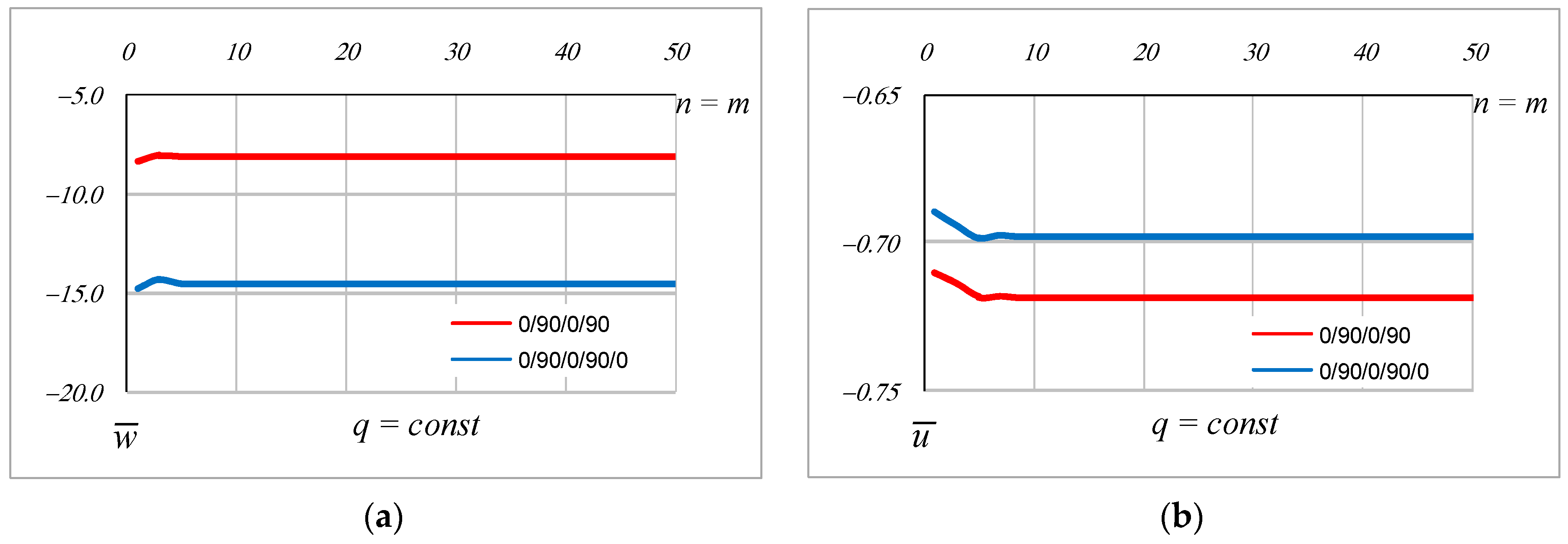
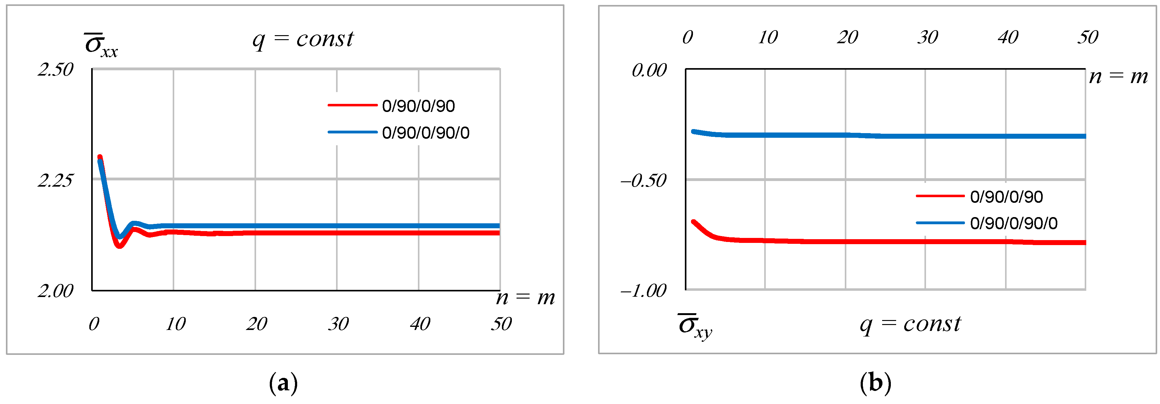
q. The influence of the change in the number of members of the trigonometric series on the change of dimensionless displacements and stresses, for a four-layer plate with an anti-symmetric lamina arrangement (0°/90°/0°/90°) and a five-layer plate with a symmetric lamina arrangement (0°/90°/0°/90°/0°), is given in
Figure 5 and
Figure 6.
It has been proven that, depending on the change in the number of members of the trigonometric series, the component displacements and stresses converge very quickly towards the exact solution, whereby a faster convergence of displacements, i.e., of primary variables, is observed. For n = m = 50, equal values were obtained, as in the previous step, for displacements and normal stresses, while the difference of the obtained values for shear stresses σxy was of the 10−5 order.
The number of members of the trigonometric series is entered as input, depending on the adopted accuracy. For the examples given in this paper, m = n = 35 was adopted, where an error of the value of shear stresses occurs, which is in the range from 10−4 to 10−5. It was noticed that there are divergence problems for very thin plates with a larger aspect ratio b/h, as well as for elongated plates with a higher a/b ratio, which will be the topic of further research.
A comparison of the values of the output variables calculated using the calculation procedure based on the new approach for the cross-section with delamination was performed, in relation to the existing tabular data given in the literature [
1,
14,
25,
28,
29,
36,
38] for a cross-section without delamination (
Table 1). To be able to make a comparison, in the extensive literature, the authors did not find appropriate comparative data for cross-sections with delamination that deal with delamination in the way given in this paper. Future research may be directed towards verifying the accuracy of this procedure with appropriate numerical values, using one of the existing software packages, for example ANSYS. However, one of the important obstacles is that software packages cannot provide the “zero state” of stress and strain, which is presented in this paper as a novelty, in situations where you have a “gap” that is local and given at a point without the previously defined dimensions of that gap. In other words, the dimension of delamination is the input data for software programs that involve delamination, by introducing a contact finite element of the final dimensions with appropriate contact conditions.
For the different ratios
b/
h = 4,
b/
h = 10 and
b/
h = 20,
Table 1 shows comparative dimensionless values of deflection, and normal and shear stresses for a square simply supported plate with a symmetric lamina arrangement (0°/90°/90°/0°), loaded with a transverse bi-sinusoidal load. Delamination is located between the second and third lamina, which leads to stress redistribution.
Based on the values obtained by the new calculation procedure, it has been noticed that with an increasing b/h ratio, displacement values increase abruptly and begin to diverge by values greater than 20, thus it can be concluded that the proposed new calculation procedure for the cross-section with delamination can be applied for moderately thin, moderately thick, and thick plates. A detailed analysis of the influence of the change in plate thickness on the values of component displacements and stresses, as well as the application of the proposed calculation procedure in this paper, will be the subject of further research.
On the grounds of the data given in
Table 1, it has been concluded that, depending on the plate thickness and the chosen theory or calculation procedure, for a cross-section without delamination, larger dimensionless values of deflection and normal stresses up to 70% are obtained. For shear stresses in the plane (
x,
y), smaller values are obtained, with the largest differences referring to the plates of the ratio
b/
h = 4. It is concluded that the occurrence of delamination in the cross-section significantly changes the maximum values of the component stresses.
In order to gain a broader insight, along with presenting a new calculation procedure in this paper, it is necessary to perform a more detailed analysis of the influence of all input variables on output parameters, component stresses, and component displacements. A detailed analysis of the application and limits of application of the proposed calculation procedure with delamination will be the subject of subsequent research.
3.2. Numerical Example
In the example that follows, the displacements and stresses through the cross-section of a simply supported five-layer plate with a symmetric lamina arrangement (0°/90°/0°/90°/0°), and with delamination at the connections of the second and third lamina, are shown in detail. The plate is transversely loaded with the uniformly distributed load q. The dimensions of the plate are defined by the ratios a/b = 1 and b/h = 4 and the height of each lamina h/5. Material characteristics of all laminae are the same and are listed above.
Figure 7,
Figure 8 and
Figure 9 show the change of dimensionless displacements and stresses through the thickness of the plate for the cross-section with and without delamination at the points, with coordinates as follows:
In a cross-section with delamination, delamination is at a point of the bond between the second and third layers.
Figure 7 shows the change of displacement
and
through the thickness of the plate with a symmetric lamina arrangement (0°/90°/0°/90°/0°) for the cross-section with and without delamination, where Δ
is the length and Δ
the width of delamination.
Figure 8 and
Figure 9 show the change of normal stresses and
and
and shear stresses and
and
through the thickness of the plate with a symmetric lamina arrangement (0°/90°/0°/90°/0°) for a cross-section with and without delamination.
At the second and third lamina connection, delamination significantly changed the internal stress–strain state. It was observed that the displacements and stresses were of significantly higher values in the case of a cross-section with delamination. Due to the above, it is important to include the effects of delamination in the calculation when dimensioning a laminated composite plate, which would prolong the exploitation period of the laminated construction.
For the same considered square five-layer laminated plate 0°/90°/0°/90°/0°, with a delamination that is located between the second and third lamina,
Figure 10 shows the change of dimensionless values of sliding Δ
, depending on the change of the coordinate
x that determines the variable position of the delamination at the point through the length of the plate. It is emphasized that, in
Figure 10, the delamination is given at one point with coordinate (
x; 0.5; 0.1), whereby the coordinate
x changes the position of the point of delamination throughout the length of the plate. It is shown that the change in the value of the delamination Δ
, in the direction of the
x-axis (depending on the position throughout the length of the plate), is an asymmetric value for the considered plate.
4. Conclusions
This paper presents a new approach to the embedding of delamination in the analytical procedure of determining the stress–strain state in laminated composite plates with an internal delamination at the point of a coordinate (x, y, z), which occurred during the production process. The new approach, with the new analytical calculation procedure shown in this paper, is based on a mathematical model of the layerwise theory and has been applied to define the stress–strain state of simply supported laminated composite plates strained to bending. The authors of this paper have automated a calculation method by designing a program code in the Fortran programming language, which can be easily upgraded.
The paper discusses a laminated plate that contains interlayer delamination, i.e., a gap, at the bond of two adjacent laminae. Depending on the change in the number of members of the trigonometric series, it has was proven that the dimensionless values of the component displacements (primary output) and stresses (secondary output) calculated by the new approach and the new analytical calculation procedure converge very quickly towards the exact solution. It was concluded that the solutions are stable and converged for thick, moderately thick, and moderately thin laminated plates. Unstable and/or divergent solutions were obtained for thin and very thin plates. To be able to compare and determine the accuracy of the reported procedure, in the extensive literature, the authors did not find any appropriate comparative data for cross-sections containing an initial delamination at a point of the bond between two laminae. For this reason,
Table 1 presents a comparison with the data from the literature for a cross-section that does not contain delamination. It is shown that the existence of delamination causes a significant change in the maximum values of displacements and stress. For this reason, the characteristic dimensionless values of displacement and stress, obtained using the new method for cross-section containing delamination, were compared with the corresponding values (available in the literature) for a cross-section without delamination for a four-layer laminated plate 0°/90°/0°/90°. It was proved that in a cross-section with delamination, significantly higher values of displacement and stress are obtained.
This new approach to the embedding of delamination is based on the calculation procedure of the layerwise theory, whereby the output data represent the value of “sliding” at the point where there is no bond between two laminae, i.e., the value of the “separation” or the value of the delamination in the plane (x, y) is determined. The new approach of defining a “zero state”, and stress and strain state, for the cross-section with internal delamination can be further used as a test solution for numerically or experimentally obtained results. The procedure presented in the paper can be improved, expanded, or supplemented by including new members in the mathematical model, related to new types of loads, the initial geometry of delamination in situations when the gap is not local, as well as with nonlinear effects dealing with the growth, development, and propagation of delamination. These effects will be the object of future research.


