Article

Image Encryption Algorithm Using 2-Order Bit Compass Coding and Chaotic Mapping

1
College of Electronic and Information Engineering, Nanjing University of Aeronautics and Astronautics, Nanjing 211106, China
2
College of Finance and Mathematics, Huainan Normal University, Huainan 232038, China
*
Author to whom correspondence should be addressed.
Symmetry 2022, 14(7), 1482; https://doi.org/10.3390/sym14071482
Submission received: 31 May 2022 / Revised: 11 July 2022 / Accepted: 12 July 2022 / Published: 20 July 2022

Abstract

:
This paper proposes a novel image encryption algorithm based on an integer form of chaotic mapping and 2-order bit compass diffusion technique. Chaotic mapping has been widely used in image encryption. If the floating-point number generated by chaotic mapping is applied to image encryption algorithm, it will slow encryption and increase the difficulty of hardware implementation. An innovative pseudo-random integer sequence generator is proposed. In chaotic system, the result of one-iteration is used as the shift value of two binary sequences, the original symmetry relationship is changed, and then XOR operation is performed to generate a new binary sequence. Multiple iterations can generate pseudo-random integer sequences. Here integer sequences have been used in scrambling of pixel positions. Meanwhile, this paper demonstrates that there is an inverse operation in the XOR operation of two binary sequences. A new pixel diffusion technique based on bit compass coding is proposed. The key vector of the algorithm comes from the original image and is hidden by image encryption. The efficiency of our proposed method in encrypting a large number of images is evaluated using security analysis and time complexity. The performance evaluation of algorithm includes key space, histogram differential attacks, gray value distribution(GDV),correlation coefficient, PSNR, entropy, and sensitivity. The comparison between the results of coefficient, entropy, PSNR, GDV, and time complexity further proves the effectiveness of the algorithm.

1. Introduction

The sharing of information is increasing in modern digital world. The information consists of text and multimedia data which require security [1]. Among these data, the digital images transmitted over the Internet are vulnerable to various attacks. Generally, securing digital images could be achieved by using image steganography [2], image encryption [3,4], and image watermarking [5]. Encryption is the most straightforward and most efficient method to ensure image security via converting the plain image into an unreadable one using a secret key [6]. Without having that secret key, nobody can restore the plain image. Many image encryption algorithms include two stages, namely, pixel scrambling and diffusion [7]. The security of cryptosystem depends on the complexity of key rather than the confidentiality of algorithm, which is the basic principle [8]. In the image encryption algorithm, whether it is the scrambling of pixel spatial position or the transformation of pixel value, it needs a complex random sequence. Therefore, the complexity of random sequence is one of the main factors that determine the superiority of encryption algorithm. Image encryption techniques are broadly classified into some categories, spatial domain, transform domain [9,10], optical [11],compressive sensing [12,13,14,15],and neural network [16,17,18]. In recent years, chaotic systems have been widely accepted because of their sensitivity to initial conditions, pseudo randomness, and ergodicity of data [19]. In 1989, Robert Matthews gave the generating function of encrypted pseudo-random number sequence based on the deformation of Logistic mapping [20]. Then chaotic cryptography and chaotic cryptanalysis are developed one after another. The image encryption algorithm based on chaotic system mainly adopts the following chaotic maps: one-dimensional logistic map, two-dimensional Henon mapping [21,22], three-dimensional Lorenz mapping [23], hybrid chaotic mapping [24], spatiotemporal chaotic [25], skew tent mapping [26,27], piecewise nonlinear chaotic mapping [28], and so on. There are some defects in the random sequence generated by chaotic system. In the limited precision, the discrete chaotic system has a simple structure, the calculation cost is very small, which can quickly generate a random sequence in the computer system. The chaotic behavior of some discrete chaotic systems is not complex, so they cannot meet the requirements of multimedia file data encryption. Therefore, these discrete chaotic system needs to transform for achieved high randomness [29]. The floating-point sequence generated by chaotic system can be applied to image encryption system only after it is converted into integer sequence. The approximation brought by data conversion will inevitably reduce the randomness and initial value sensitivity of chaotic mapping.
Generally, many image encryption processes usually include two stages. Ref [30] has proposed the application of random integer in image encryption based on chaos. There are two problems by which the block processing of the image affects the applicability of the algorithm and cyclic shift applies only permutation of pixels. Ref [31] proposes an encryption algorithm in combination with cyclic shift and sorting. But the performance of the algorithm depends on the early grouping of images. In ref [32], double chaotic systems are used to generate a random sequence, which is a non-integer. Therefore, in encryption applications, random numbers must be integer preprocessed that directly affects the effect of pixel diffusion. In the application of pixel diffusion, these methods do not apply cyclic shift to the bits of pixels. In order to avoid integer preprocessing of random numbers and improve pixel diffusion performance, this paper aims to propose pseudo-random integers generation scheme-based chaotic map and pixel diffusion method based 2-order bit compass. In the image encryption algorithm, the pixel position is scrambled by random sequence, and then the pixel diffusion is realized by using the bit compass coding. In the first section, the generation method of pseudo-random integer sequence is studied based on chaotic mapping. The binary sequences of several integers can be combined with chaotic mapping, and multiple groups of different new binary sequences can be obtained by using the XOR operation after shift. This part not only demonstrates the feasibility of the method, but also demonstrates the randomness of the random integer sequence generated by the method and its sensitivity to the initial value. The second section designs bit compass coding. The existence of Euler rings of regular bipartite graphs is demonstrated, and the reversible condition of the bit compass coding is proposed. The last section is the experimental demonstration to test the feasibility and superiority of the algorithm.

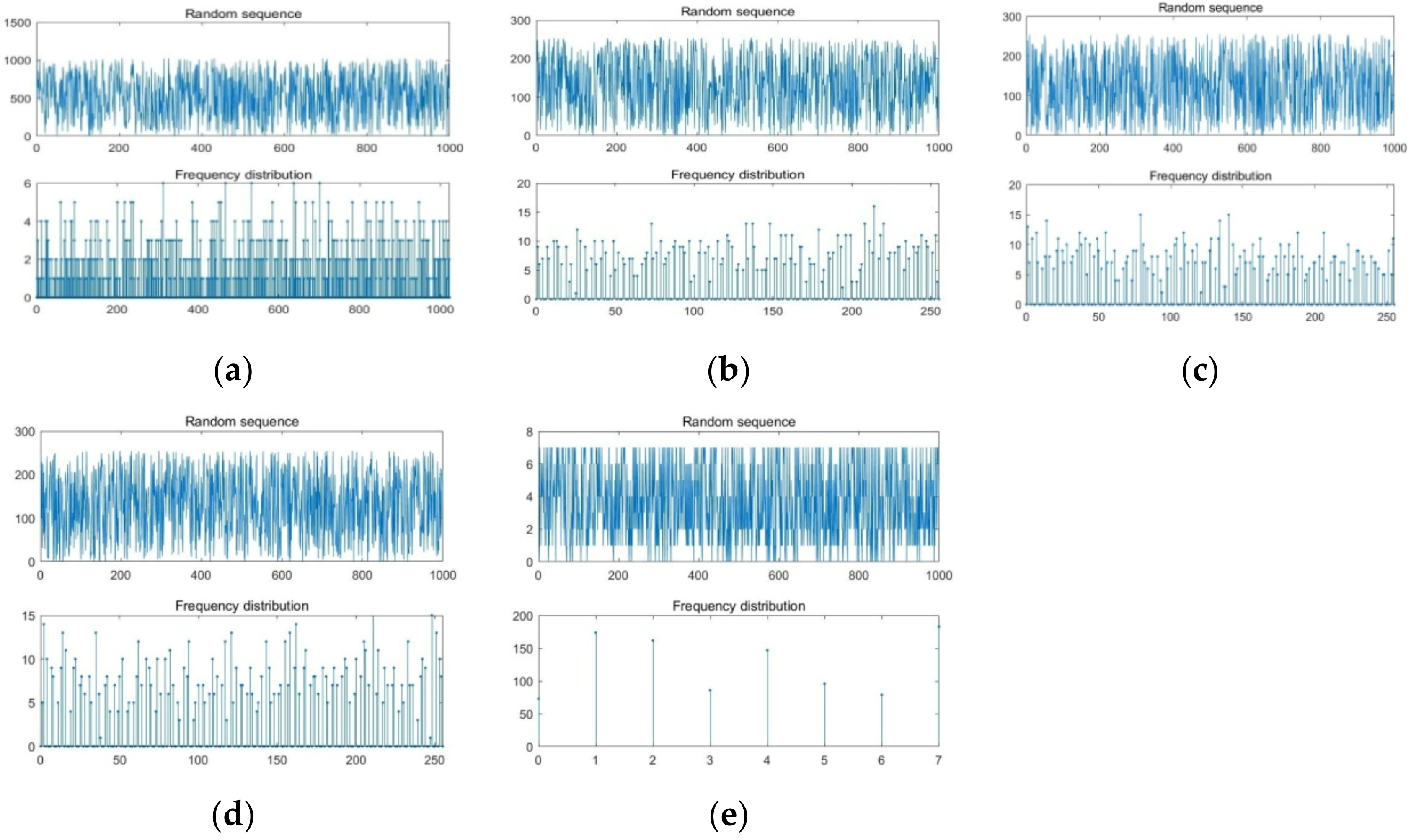
2. Pseudo-Random Integer Sequence Generator

The commonly used chaotic map in image encryption system is logistic mapping. Because of its simple structure and sufficient chaotic level, one-dimensional logistic map has become a widely used chaotic mapping. Equation (1) shows the logistic mapping [33],
x n + 1 = μ × x n × ( 1 x n )
The value µ ∈ (0, 4], x n (0, 1). The µ is limited to a range of [3.75, 4] to ensure the chaotic behavior. Figure 1 shows the bifurcation diagram of the logistic mapping.
Within the limited precision, the randomness of the sequence x n will decrease. For example, 100 × x n can be rounded to obtain the sequence of integers. The statistical results of the random integer sequence are shown in Figure 2. When there are different initial values and parameters, appearing frequency of 0~20 and 90~100 in the random integer sequence is very few. It is necessary to recombine the integer sequence generated by chaotic mapping to improve the randomness. Here, we give a scheme to generate pseudo-random integer sequence by combining chaotic mapping with XOR. r 1 and r 2 are binary sequences with length n of two random integers R 1 and R 2 , respectively. The pseudo-random integer generated by chaotic mapping is used as the shift amount of cyclic shift of sequence r 1 and r 2 , and then XOR operation is performed to generate a new binary sequence with length of n.
In the Algorithm 1,the initial value of chaos x 0 ∈ (0, 1), µ ∈ (3.75, 4], two integers R 1 , R 2 , times are the length of the generated integer sequence, and n is the bit number of the integer. The output result is times integers R. In the fourth step in the Algorithm 1, the formula r 1 (end) ⇐ abs( r 2 (end) − 1) is the inverse of the last bit of r 2 . This formula can achieve two purposes, one is to increase the randomness of the generated integers, and another is to avoid the situation that the bits of two integers are all 1 or 0. The sixth step of the floor is the integer operation. In the eighth step, mod() is a modular operation, circshift(a, b) is a binary sequence cyclic shift of b bits, and bitxor(a, b) is the XOR operation of two bit sequences. The results of five different parameters are given in Figure 3. It can be found that there are great differences in the generated integer sequence when the parameters change slightly. The pseudo random integer sequence will be applied to pixel scrambling of proposed image encryption scheme. The logistic map in Algorithm 1 can be replaced, and pseudo-random integer sequences can also be generated. Generally, one-dimensional chaotic systems include Tent mapping, Chebyshev mapping, Sine mapping, and Cubic mapping [34].
Algorithm 1 Random Integer Sequence
Require: µ ∈ [3.7, 4] ∨ x 0 ∈ (0, 1) ∨ R 1 , R 2 ∈ N ∨ times, n ∈ N+
1 r 1 , r 2 ⇐ Convert R 1 , R 2 to binary sequence of long n.
2 for i = 1: times do
3 r 2 ⇐ ∼ r 2 ;
4 r 2 (end) ⇐ abs ( r 2 (end) − 1);
5   1 ⇐ µ ∗ x 0 ∗ (1 − x 0 );
6    x i 0 ⇐ floor( x 0 ∗ 100)); /*Extract two integers after the decimal point.*/
7     x i 1 ⇐ floor( x 1 ∗ 100));
8     R 1 ⇐ bitxor(circshift( r 1 , mod( x i 0 , n)), circshift( r 2 , mod( x i 1 , n)));
9     R ⇐ Convert R i to a decimal;
10    x 0 x 1 ; r 0 r 1 ; r 1 R i
11 Output: R ⇐ unique(R, ‘stable’)
Chebyshev mapping:
x n + 1 = cos ( n × cos 1 ( x n ) ) ,   x n   [ 1 ,   1 ] , µ 2
Tent mapping:
x n + 1 = x n μ , x n < μ 1 x n 1 μ , x n μ , x n 1 ,   1 ,   μ 0 ,   1
Sine mapping:
x n + 1 = μ 4 × s i n π × x n ,   μ     [ 0 ,   1 ]
Cubic mapping:
x n + 1 = μ 4 × x n 1 x n 2 ,   μ     [ 0 ,   1 ]
The experimental results of pseudo-random integer sequence under four different mappings are given in Figure 4.

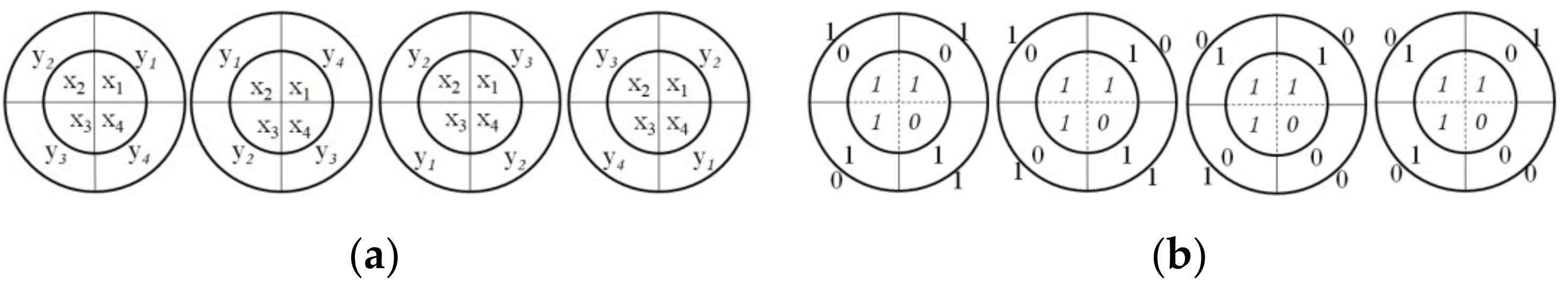
3. Bit-Compass Coding

An image with 1 bpp will use only 1 bit for each pixel, therefore each pixel will beat a certain point 1 or 0 [35]. If input bits are the same, then the output will be false(0) else true(1),which is XOR. The encryption scheme in this paper is to generate a new data set by using the XOR operation of the data set. First, two integers are converted into two group codes, binary codes with the same length. After a group of binary codes are shifted circularly once, a cipher-text is generated by XOR operation that applying to bits in the same position. The original two groups of binary codes are plaintext, the shift is the key, and the new binary codes are cipher-text. The paper proposes a rotating compass to describing the generation process of cipher-text. Supposed x 1 , x 2 , x 3 , x 4 and y 1 , y 2 , y 3 , y 4 are 4-bit binary codes of integers x and y respectively. Here, x i , y i ∈ {0, 1}. Two sets of bits are arranged according to the pattern of Figure 5a. The pattern is named of four 2-order bit compass ( B C 4 , 2 ). The B C 4 , 2 has an inner disk and an outer disk, the inner disk is the binary array of x and the outer disk is the binary array of y. In the encryption process, the inner disk remains stationary and the outer disk can rotate freely. Turn one angle θ (0°, 90°, 180°, 270°), a new 4-bit code C can be generated after XOR operation. It is easy to know that a B C 4 , 2 can generate up to four different binary codes. Where, x and y are plain-text, θ is the key and C is the cipher-text. For simplicity, k = 0, k = 1, k = 2, k = 3 respectively represent the counterclockwise rotation angle of the outer disk. The processing structure is shown in Figure 5a.
For example, the 4-bit binary of plaintext x = 14 and y = 3 is 1110,0011. The pseudo-random integer sequence generation algorithm can refer to the diagram in Figure 5b. In Figure 5b it is shown that we can get four different cipher-text C. Cipher-text C is 1101,0111,0010,1000 respectively under four different rotations. Using the above method, plaintext 14 and 3 can generate cipher-text 13, 7, 2, 8. The decoding of 2-order m-bit compass uses cipher-text to generate plaintext through appropriate operation. The number of disks and bits are increased to improving randomness of the generated sequence. A 2-order bit-compass program is provided in Algorithm 2. Higher-order bit-compass is defined as follows.
Algorithm 2 A Time Coding of B C m , 2
Require: R 1 , R 2 is two plaintext binary sequence of long m. k is rotation angle of outer wheel disc.
1: R p ⇐ bitxor( R 1 , circshif t( R 2 , mod(k, m)));
Definition 1.
(n-order bit-compass) Let x 1 , x 2 , …, x n are n integers. Converting them into m-bit binary code, and seting x i , j is the j-th bit of x i . Arranged as shown in Figure 6 below, the compass formed is called n-order bit-compass ( B C 4 , 2 ). The counterclockwise rotation angle k of the i-th disk is recorded as k e y i , k .
The outer n − 1 discs can rotate, and each disc has m different rotation angles. Therefore, there are mn−1 different rotation combinations. If a rotation can generate a cipher-text, there are mn−1 cipher-texts in total. Due to the different rotation modes of n − 1 outer disks, up to mn−1 different cipher-text combinations can be generated. The arbitrary rotation of the n − 1 outer disks can generate a set of pseudo-random numbers, such as Algorithm 3.
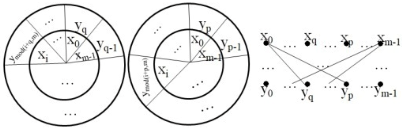
Algorithm 3 Pseudo-Random Sequence of the BC m , n
1 Input → Vector A with length n.
2  Abit ⇐ Each element of vector A is transformed into a binary sequence of length m.
3  z ⇐ Abit(1,:);
4  k ⇐ mn−1;
5  for i = 0: k − 1 do
6  c = n − 2;
7    for j = 2: n do
8     t ⇐ floor(i/mc);
9 z ⇐ bitxor(z, circshif t(Abit(j,:), t))
10 c = c − 1;
11 i ⇐ i − t × mc;
12 end for
13 z ⇐ [r; z];
14  end for
15  B ⇐ Each row of the matrix r converts m bits into a decimal number.
16 Output → Vector B with length mn − 1
Where, floor(i/mc) is the rounding of i/mc, representing shift value of the j-th vector group Abit. bitxor(z, circshif t(Abit(j,;), t))is an XOR operation after the shift of the vector group Abit. For example, let BC 8 , 4 composed of four numbers 118, 93, 102, 230. The plaintext is [01110110; 01011101; 01100110; 11100110]. They can generate 512 integers with variance of 6800.5. The histogram and frequency distribution of cipher-text array show in Figure 7 that these data have strong randomness. The next section will show the decoding conditions and methods of the bit-compass.

4. Bit-Compass Decoding

Based on the B C m , 2 , we decode the bit-compass one by one from the outside to the inside. The internal n − 1 disks in the n-order bit-compass are regarded as an internal disk, that is, the n-order bit-compass can be regarded as a 2-order bit-compass. The outermost disc can be decoded according to the 2-order bit-compass decoding method. In the same way, the remaining n − 1 disks in the inner layer are decoded in turn. Therefore, the decoding process needs n − 1 times to end. The following contents of this chapter mainly describe the decoding of 2-order bit-compass and the problems encountered in decoding. The encryption processing shows that each bit of the cipher-text indicates the relationship between the two bits in the plaintext. If the logical relationship of all bits in the plaintext can be found, the plaintext can be determined. In the B C 4 , 2 , the external disk rotate twice, and each rotation will produce a one-to-one correspondence between bits, which is indicated by the bits of the cipher-text. If each bit is set as a vertex and the correspondence between bits is taken as an edge, the correspondence after each rotation of the 2-order bit-compass can be described as a bipartite graph, depicted in Figure 8. All vertices are on a loop in Figure 8a, which is not the case in Figure 8b. Therefore, it shows that the success of decryption is conditional.
Theorem 1.
(Sufficient conditions for the existence of Euler loop) Undirected graph G = ( V 1 , V 2 , E) is a 2-regular bipartite graph, and the number of vertices of V 1 is the same as that of V 2 . If the number of vertices of V 1 is a prime number, then the undirected graph G has an Euler loop.
Proof of Theorem 1.
Let two integers x and y, and their m bits binary codes are x 0 , x 1 , …, x m 1 and y 0 , y 1 , …, y m 1 , in which x i , y i ∈ 0, 1. Figure 9 shows that k = p and q are respectively used to represent the different two rotations of the outer disk of BC 4 , 2 ,. 0 ≤ pq ≤ m−1, p, q ∈ ℤ +. Let p > q. A 2-regular bipartite graph can be constructed in Figure 9. Let x i is a bit of x, 0 ≤ i ≤ m − 1. The 2-regular bipartite graph is as follows.
x i y m o d i + p , m x m o d m o d i + p , m q , m
Since x i = x m o d i , m , we have
x m o d m o d i + p , m 1 , m = x m o d m o d i + p , m m o d q , m , m = x m o d i + p q , m
so
x i y m o d i + p , m x m o d i + p q , m
Similarly, we can be obtained
x m o d i + p 1 , m y m o d m o d i + p 1 , m + p , m x m o d i + 2 p q , m
Repeat the above operation to get a circuit.
x i y m o d i + p , m x m o d i + p q , m y m o d m o d i + p q , m + p , m x m o d i + 2 p q , m x m o d i + m 2 p q , m x m o d i + m 2 p q , m y m o d m o d i + m 2 p q , m + p , m . x m o d i + m 1 p q , m y m o d m o d i + m 1 p q , m + p , m x m o d i + m p q , m x i
If m is prime, then x m o d i + s p q , m x m o d i + t p q , m , when s t . It is now easy to show that the loop contains all 2m vertices. Therefore, the loop is an Euler loop (6).  □
A 2-order bit-compass decoding program is provided in Algorithm 4. With the above analysis, the number of bits of integers x , y needs to be primes to successfully realize decoding. After determining the relationship between plaintext bits, all bits can be obtained as long as it is determined that a bit is 0 or 1. In the image encryption algorithm in this paper, we extract the first bit of the outermost disk as the key to realize the successful decoding of the Algorithm 4.
Algorithm 4 Random Integer Sequence
Require: µ ∈ [3.7, 4] ∨ x 0 ∈ (0, 1) ∨ R 1 , R 2 ∈ N ∨ times, n ∈ N+
Require: R p 1 , R p 2 is two cipher-text binary sequence of long n. k e y 1 , k e y 2 is rotation angle of outer disk R 1 , R 2 . First bit F b i t , R 2 of inner disk R p 1
1   i ⇐ 1; n1 ⇐ n; R 1 ⇐ zeros(1, l);
2 while i < n do
3    n 2 ⇐ mod( n 1 + k e y 1 , n);
4    if n 2 == 0 then
5     n 2 ⇐ n;
6    end if
7    temp ⇐ mod( n 2 k e y 2 , n);
8    if temp == 0 then
9    temp ⇐ 1;
10   end if
11   if R p 1 ( n 2 ) == R p 2 ( n 2 ) then
12     R 1 (temp) ⇐ R 1 ( n 1 );
13    else
14     R 1 (temp) ⇐ m o d ( R 1 ( n 1 ) + 1,2);
15    end if
16     n 1 ⇐ temp; i ⇐ i + 1;
17    end while
18 b ⇐ [ R 1 (n − k e y 1 + 1: n), R 1 (1: n − k e y 1 )]
19 n 2 ⇐ mod( n 1 + k e y 1 , n);
20for i = 1: n do
21   if R p 1 (i) == 1 then
22     R 2 (i) ⇐ mod(b(i) + 1, 2)
23   else R 2 (i) ⇐ b(i)
24   end if
25end for
26 temp ⇐ R 2
27 R 2 R 1
28 R 1 t e m p
29 if F b i t == 1 then
30   R 2 ⇐ mod( R 1 + 1, 2);
31    R 1 ⇐ mod( R 2 + 1, 2);
32 end if
33 Output: R R 1

5. Proposed Scheme of Image Encryption

In this section, we focus on the application of 2-order bit-compass encryption method in image encryption and decryption, which is called bit-compass image encryption system(BCIES). Encryption is divided into two processes including pixel scrambling and pixel diffusion. The decryption algorithm is reverse of the encryption algorithm.
Pixel scrambling changes the correlation between adjacent pixels, in which using the XOR operation between adjacent pixels is more conducive to pixel diffusion processing. The proposed Algorithm 5 presents the process of pixel scrambling.
Algorithm 5 Pixel Scrambling
R equire: Original image I with size M × N and the vector R longer than M × N
1 k ⇐ 1;
2 for i= 1:M do
3     f o r   j = 1 : N   d o
4     if n 2 == 0 then
5      I r i , j ⇐ I(R(k), R(k + 1));
6    k ⇐ k + 2;
7    end for
8end for
Output Ir
In Algorithm 5, the vector R is given by Algorithm 1. The pixel diffusion part includes image transformation, key generation, and encryption.
  • Step 1: Each element of Ir is transformed into an 8-bit binary code to generate I b M × 8 N matrix.
  • Step 2: Any even number greater than 2 can be written as the sum of two prime numbers [36]. Decompose an even number 8N into the sum of two prime numbers.
    8 N = c 1 + c 2 .       s . t . a r g m i n c 1 + c 2
  • Step 3: Extract the first and ( c 1 + 1)-th bit from the odd rows of matrix I b M × 8 N to construct the matrix I b f M 2 × 2 . In the decoding process, the first code of the external roulette comes from the matrix I b f M 2 × 2 .
  • Step 4: Keep the order of elements in I b f M 2 × 2 unchanged and construct the matrix I k e y M 16 × 16 . The missing number can be replaced by 0.
  • Step 5: 16 bits 0 and 1 in each row of matrix I k e y M 16 × 16 are converted into a decimal integer to generate a key vector key with a length of m16. The vector key is saved as a key. In later decryption, the first element of the bit compass code and the rotation angle of the outer disk (cyclic shift amount) can be determined from the vector key. The algorithm can refer to Algorithm 6.
    Algorithm 6 Key Generation
    1 Input → The image Ir with size M × N
    2: Convert image Ir into 8-bit binary matrix I b M × 8 N
    3 z e r o s I k ⇐ [Ib(2: 2: r, 1); Ib(2: 2: r, c1 + 1)]
    4Ikey ⇐ reshape( z e r o s I k , floor(length( z e r o s I k )/16), 16)
    5 for i = 1: length( z e r o s I k )/16 do
    6key(i) ⇐ ConverteIkey(i,:) to decimal integer.
    7end for
    8 Output → key
When encrypting an image with the size of M × N by using the 2-order bit-compass coding, if there are four rotation angles per two lines, there will be 2M in total.
  • Step 1: Extract n = l o g 16 2 M + 1 elements from key, and use the Algorithm 4 to generate vectors Ekey with length of 2M, where m = 16 , n = l o g 16 2 M + 1 .
  • Step 2: The adjacent two rows of the matrix I b M × 8 N are encrypted in turn.
After M/2 times of the same encryption, the image encryption is completed. Refer to Algorithm 7.
Algorithm 7 Data Encryption
1 Input → the matrix I b M × 8 N and the vectors Ekey.
2 while i< M do
3 Select four consecutive numbers from the vector Ekey. The first two modulo operations with c 1 get k 1 , k 2 and the last two modulo operations with c 2 get k 3 , k 4 ;
4 I 2 (i + 1, 2: 2: c 1 ) ← abs( I 2 (i + 1, 2: 2: c 1 ) − 1)
5    I 2 (i + 1, c 1 + 2: 2: c ∗ n) ←abs( I 2 (i + 1, c 1 + 2: 2: c ∗ n) − 1)/*Change the correlation of adjacent pixels.*/
6   if k 1 k 2 then
7  EIB ← The first c 1 numbers of i-line and (i + 1)-line of Ib are encrypted by B C c 1 , c 2 and the keys are k 1 , k 2
8  else EIB ← The first c1 numbers of i-line and (i + 1)-line of Ib are encrypted by B C c 1 , c 2 and the keys are k 1 , k 2 + 1;
9 end if
10   if k 3 k 4 then
11   EIB ← The first c 1 numbers of i-line and (i + 1)-line of Ib are encrypted by B C c 1 , c 2 and the keys are k 3 , k 4
12else EIB ← The first c1 numbers of i-line and (i + 1)-line of Ib are encrypted by B C c 1 , c 2 and the keys are k 3 , k 4 + 1;
13   end if
14i ← i + 2;
15Delete the first four numbers from the vectors Ekey.
16 end while
17EI ← Every 8 bits in matrix EIB are converted into a decimal number.
18 Onput → The matrix EI
This encryption method is based on the recoding of two rows of pixels. Due to the high local correlation of the image, the effect of one-time encryption may not be good, so multiple encrypted can be used, or the selection method of two lines can be changed. The decryption algorithm is reverse of the encryption algorithm. Different from encryption, the B C m , 2 in decryption uses Algorithm 4.

6. Results and Analysis

The encryption algorithm runs in a personal computer with a CPU 2.3 GHz and the operating system is Microsoft Windows 10. The program is based on MATLABR2021 platform. The proposed image encryption algorithm has been implemented on 5 benchmark images; the circles image( I 1 . png 256 × 256 ), the cameraman image( I 2 . tiff 256 × 256 ), the concordorthophoto image ( I 3 . png . png 2215 × 2956 ), the trailer image( I 4 . jpg 256 × 256 ) and the westconcordorthophoto image( I 5 . png 263 × 366 ).The key space, histogram, λ 2 text, correlation coefficient, PSNR, information entropy, GVD, differential attack and speed performance of the algorithm are tested. On the far left in Figure 10a–e are five original images I1, I2, I3, I4, I5 of different sizes. The second of Figure 10a–e is a scrambled image of them. Here µ = 3.8, x 0 = 0.49, R 1 = 100, R 2 = 210, times = 6000, n = 12. The third in Figure 10a–e is encryption image of them respectively. The pixel diffusion operation of the image applies twice 2-order bit-compass. The last image is the decrypted image. The decrypted image here is exactly the same as the original image. Figure 10 shows that the information of any original image cannot be obtained from the encrypted image.

6.1. Key Space

For every encryption system, the key space is very important. The security analysis based on the simulation results are as follows. The key space of the proposed mode image encryption using pixel scrambling and diffusion consist of four key factors. In pixel scrambling, chaotic system needs five initial conditions µ, x 0 = 0.49, R 1 , R 2 , n. Where number µ, x 0 retain four digits after the decimal point, and there are at least 108 different choices. If n = 12, 12-bit integers R 1 and R 2 have at most 224 different choices. In pixel diffusion, the number of first bits extracted from plaintext images with different sizes is also different. The number of bits increases with the length of size that is determined by the image size and the times of encryption. The length of one-time encryption key of image I M × N is M × 2 2 . According to this formula, the key length generated by p-time of the encryption is 2 M × p . Table 1 presents the total key space of the proposed algorithm of the above five images. With the increase of encryption times, the total key space will also increase. The total key space of the proposed algorithm is 216×16(>2128), which protects brute-force attacks efficiently [17].

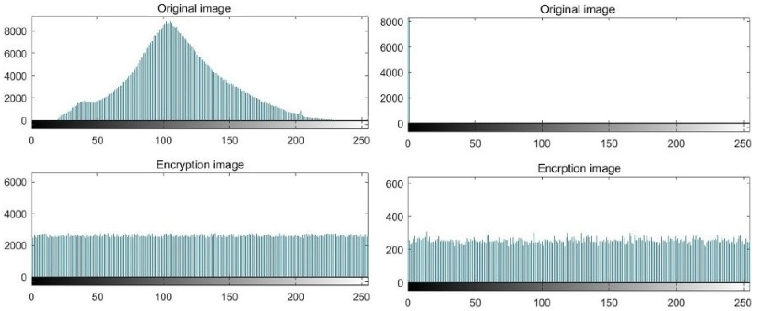
6.2. Histogram Analysis

Histogram is used to describe the pixel distribution of image. Image encryption algorithm should ensure that the pixel distribution of different encrypted images is uniform, that is, their probability of occurrence is equal. Figure 11 shows the histogram analysis results of our algorithm. The upper figure of Figure 11 is the histogram of the original image, and the below of Figure 11 is the histogram of the encryption image. The second line of Figure 11 shows that compared with the histogram of the plaintext image, the histogram of the cipher-text image is very uniform, with significant differences, which makes it difficult for attackers to analyze the information of the cipher-text image through statistical methods.

6.3. The λ 2 Text

Similar to histogram, λ 2 test is another method used to evaluate the uniformity of pixel value distribution of encrypted images. The small value of the λ 2 indicates a better uniformity of pixel distribution. For a confidence level α = 0.05, the λ 2 value should not be greater than 295.25 [37]. The smaller the variance, the higher the uniformity of image pixels, and the better the diffusion effect in the encryption algorithm [38,39]. The following Formula (8) is used to calculate the λ 2 value of an image with 256 Gy-levels [37]:
λ 2 = i = 0 255 n i n 256 2 n 256
v a r I = 1 2 n i = 0 n j = 0 n x i x j 2
where n is the number of all the pixels in an image, ni is the occurrence frequency of gray level i, i ∈ {0, 1,…, 255}. Here, x i and x j are the numbers of pixels in which gray values are equal to i and j. Compared with algorithm of Refs [13,40], the λ 2 and variance of the proposed algorithm are better, as shown in Table 2. We can draw another conclusion: the variance of the five images is smaller than that of the original image. The minimum variance of the original image is about 2.1193 × 10⁴, while the minimum variance of the password image decreases to about 7974.6, which shows that the histogram distribution of the password image is evenly distributed, and our algorithm is highly secure. In the scheme proposed in the paper, the average value of the λ 2 is only 254.5, which is lower than that of Refs [13,40].

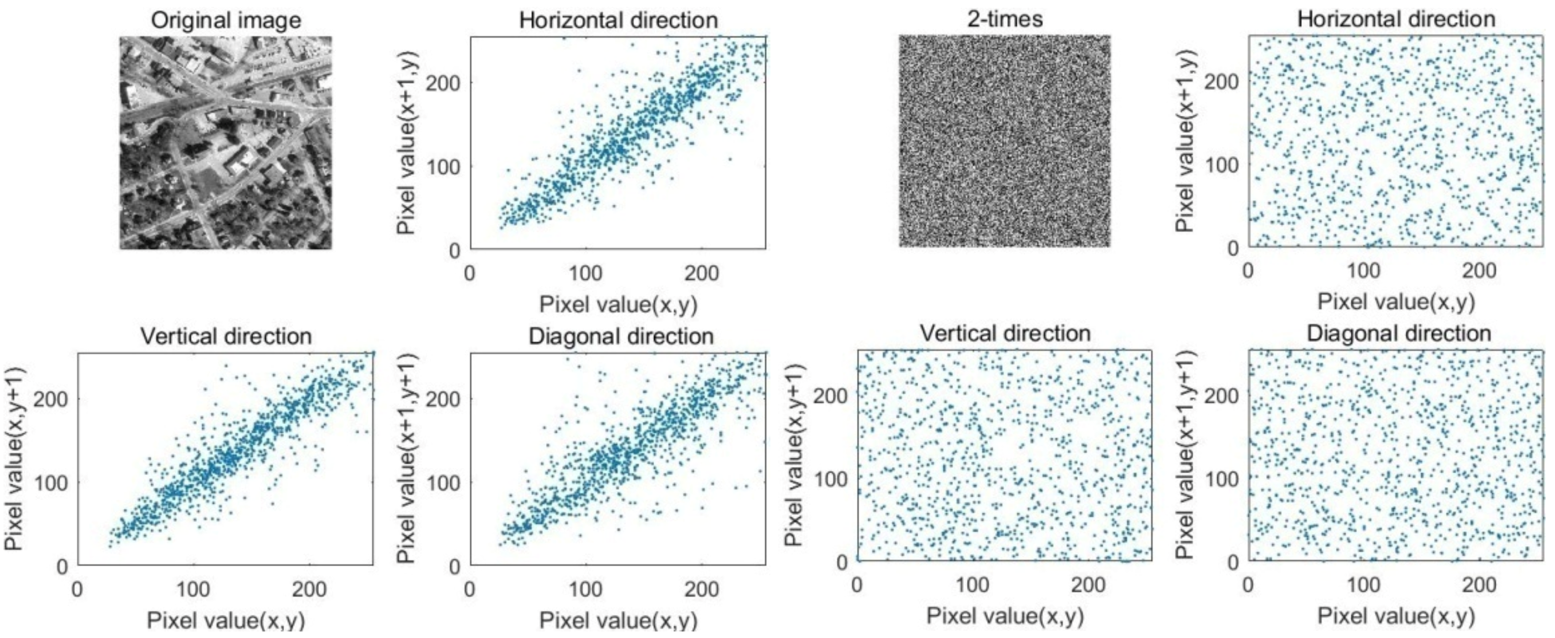
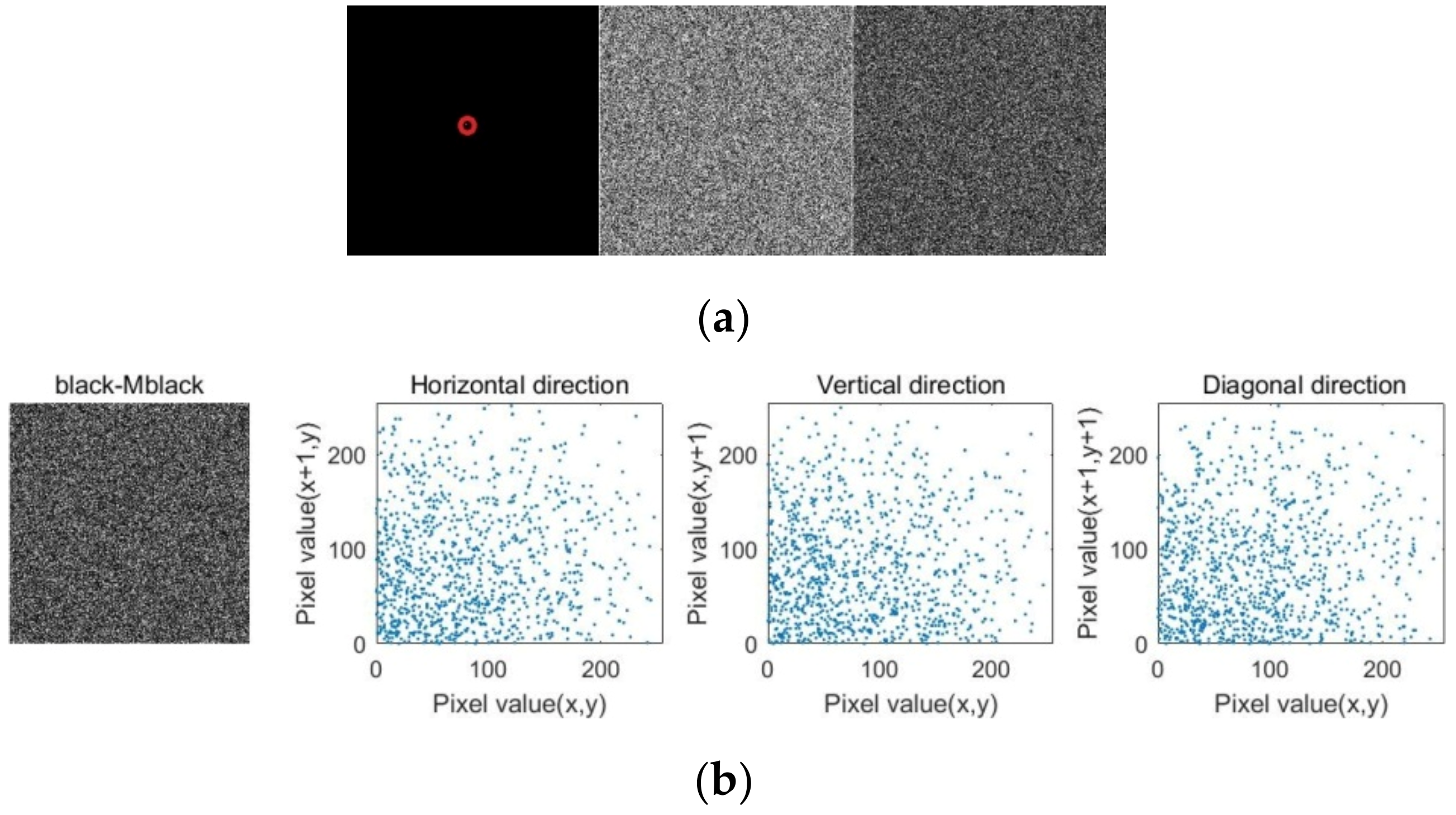
6.4. Correlation Coefficient Text

Usually, the adjacent pixels of the original image have high correlation, which will cause its adjacent (horizontal, vertical, or diagonal) pixel values to have strong similarity. Therefore, excellent image encryption algorithms should try their best to eliminate these correlations. In general images, each pixel and its adjacent pixels will show high correlation. Encryption algorithm has the stronger ability to resist attack if the correlation between adjacent pixels of cipher-text image is lower. The correlation coefficient is calculated as [40]:
c o v x , y = E ( ( x E x y E y v a r x v a r y , E x = 1 n i = 0 n x i ,   v a r x = 1 n i = 0 n ( x i E x ) 2
where, c o v x , y is the covariance of x and y , E x and v a r x are the expectation and variance of the variable x , respectively. The comparison results show the superiority of the algorithm. n is the total number of pixels chosen from the image. To illustrate the correlation, randomly select 10,000 pairs of pixels adjacent to the cipher-text image and their distribution is plotted in Figure 12, Figure 13, Figure 14, Figure 15 and Figure 16. As the figures show, the distributions of original image are close to line y = x due to the correlation between adjacent pixels. However, the distribution of the cipher-text image spreads to the whole plane. Table 3 presents the correlation coefficient results of three groups of original and encrypted images along all the directions. The results show that the encrypted images coefficient is close to 0. Compared with the high correlation coefficient in the original image, the proposed algorithm strongly resists statistical attack. We can also find that with the increase of pixel diffusion times, the correlation coefficient is closer to 0. The comparative test results are given in the Table 3, which shows that the value of the algorithm in this paper is closer to 0 compared with similar encryption algorithms of Refs [13,40].

6.5. Peak Signal-to-Noise Ratio

Peak signal-to-noise ratio (PSNR) is often used as a measurement method of signal reconstruction quality in image compression and other fields. It is often simply defined by mean square error (MSE) [41]:
M S E = 1 M × N i = 1 M j = 1 N ( I i , j E I i , j ) 2 ,   P S N R = 20 × l o g 255 2 M S E
where, I and EI represent plain and ciphered images. The average PSNR results of proposed system is 8.7317 for image I2, I3, I4, I5 shown in Table 4 that is equal to rest of the Refs [13,40]. I1is a binary image, so its PSNR is a little higher.

6.6. Information Entropy

Image information entropy refers to the degree of confusion of pixels. Entropy analysis is a mathematical criterion, which determines the level of randomness of an image. The randomness of encrypted images will improve the security of image information. Therefore, the information entropy is very useful for analyzing the randomness of encryption algorithm. In the following equation:
M S E = i = 0 n 1 p x i l o g 2 1 p m i
where, n is the number of different pixels, and p x i denotes the probability of the occurrence of pixel value x i . The Entropy( x ) of the encrypted image at 256 Gy-level should be infinitely close to 8. The information entropies for different encrypted images are measured and average value 7.9989 is also showed in the last row of Table 4. The comparison of entropies clearly indicates that proposed system has good entropies with Refs [13,40].

6.7. Gray Value Distribution

The gray value distribution (GVD) is the distribution of gray value of gray image. GVD will be 0 if two images are completely same or else 1. Suppose that the size of the original image I is M × N; hence, GVD is described by following expression [42]:
G V D I , E I = i = 2 M 1 i = 2 N 1 G N I i , j G N E I i , j i = 2 M 1 i = 2 N 1 G N I i , j + G N E I i , j G N I i , j = i , j ( I i , j I i , j ) 2 4 G N E I i , j = i , j ( E I i , j E I i , j ) 2 4 G i , j i + 1 , j , i 1 , j , i , j + 1 , i , j 1
There, EI is a cipher-text image, ( i 0 , j 0 ) are neighborhood gray value of ( i , j )-pixel. The GVD of encrypted images of I1, I2, I3, I4 and I5 is given in Table 4 and average is 0.9369, which is very close to 1. The GVD score is comparable to Refs [13,40].

6.8. Differential Attack Analysis

Differential attack analysis is a method for attackers to extract encrypted data by slightly changing the input data and considering the change of output. Usually, the opponent utilizes monochromatic images as special original images to attack the encryption algorithms, for the first pixel of the special image which is regularly arranged, and the attacker may get the secret keys and make the algorithm invalid. The Figure 17 shows the experimental result of white and black images. Only one pixel of the full black image is modified and re encrypted. The encryption result is shown in Figure 18. It can be seen that the difference between the encrypted images is very obvious.
At the same time, we also draw horizontal, vertical, and diagonal adjacent pixels of the cipher-text Image, so the proposed algorithm can resist statistical attacks.

6.9. Speed Performance

The time complexity of the algorithm is evaluated for several images of different sizes. The results are shown in Table 5 which illustrate that the time complexity of the proposed scheme is similar to Refs [13,40] in images with same length and width, however have superiority on images with different length and width.

7. Conclusions

This paper mainly solves the problem of random integer generation based on chaos and the problem of encoding and decoding of 2-order bit compass. The bit shift XOR operation of input and output enhances the randomness of integer sequence in chaotic system. The precision of random integers can be set by parameters in this scheme. This pseudo-random integer sequence provides a basis for image pixel scrambling. The second research content is disc coding based on bit rotation shift and XOR operation. The inner and outer discs of disc coding are composed of every two rows of elements of image pixels to complete the diffusion of pixels. In diffusion processing, the bit shift value as the key comes from the plaintext image, and the cipher-text image can effectively hide the key to ensure the security of the key.
Experiment results of five different types of original images illustrate that the proposed algorithm has good encryption results and may be applied for encrypting all kinds of images, such as, gray image, color image, and binary image of different sizes. In addition, we have made the security analyses on key space, key sensitivity, histogram, information entropy, correlation, the peak signal-to-noise ratio, differential attack, and gray value distribution. Compared with existing schemes, the proposed scheme has more advantages in information entropy, correlation, gray value distribution, peak signal-to-noise ratio, computation, and complexity.
The algorithm proposed in the paper has two limitations, which limit the operation speed. In image encryption, 2-order bit compass can only encrypt two lines of data at a time. The other is that pixel diffusion may be performed twice or more.
We mainly propose the random integer generation and 2-order bit compass. In the generation of integer sequences in chaotic systems, the larger the integer range, the better the random performance of the sequences. Nevertheless, this property will reduce the computational efficiency. The 2-order bit compass can effectively apply the diffusion of image pixels. However, the encryption of the 2-order bit compass can only process two lines of the image at a time. If the compass order is increased, the operation speed will be faster and the pixel diffusion effect will be better. Our main research directions are smaller range random integer sequence and the high-order bit compass decoding method in the future.

Author Contributions

Funding acquisition, Y.W.; supervision, Y.S.; validation, J.C.; writing—original draft, J.C. and Y.W.; Writing—review & editing, J.C. and C.Y. All authors have read and agreed to the published version of the manuscript.

Funding

This study was funded by National Natural Science Foundation of China (61403157), the Natural Science Research Projects in Anhui Universities (KJ2021A0965).

Conflicts of Interest

Our article only clarifies our theoretical views, without any immoral discussions and remarks. After long-term research, the author has no plagiarism and academic misconduct.

References

  1. Masood, F.; Masood, J.; Zhang, L.; Jamal, S.S.; Boulila, W.; Rehman, S.U.; Khan, F.A.; Ahmad, J. A new color image encryption technique using DNA computing and Chaos-based substitution box. Soft Comput. 2022, 26, 7461–7477. [Google Scholar] [CrossRef]
  2. Liao, X.; Yin, J.; Guo, S.; Li, X.; Sangaiah, A.K. Medical JPEG image steganography based on preserving inter-block dependencies. Comput. Electr. Eng. 2018, 67, 320–329. [Google Scholar] [CrossRef]
  3. Usman, M.A.; Usman, M.R. Using image steganography for providing enhanced medical data security. In Proceedings of the IEEE Consumer Communications & Networking Conference, Las Vegas, NV, USA, 12–15 January 2018; pp. 1–4. [Google Scholar]
  4. Etoundi, C.M.L.; Nkapkop, J.D.D.; Tsafack, N.; Ngono, J.M.; Ele, P.; Wozniak, M.; Shafi, J.; Ijaz, M.F. A Novel Compound-Coupled Hyperchaotic Map for Image Encryption. Symmetry 2022, 14, 493. [Google Scholar] [CrossRef]
  5. Hosny, K.M.; Darwish, M.M. Robust color image watermarking using invariant quaternion Legendre-Fourier moments. Multimed. Tools Appl. 2018, 77, 24727–24750. [Google Scholar] [CrossRef]
  6. Kamal, S.T.; Hosny, K.M.; Elgindy, T.M.; Darwish, M.M.; Fouda, M.M. A new image encryption algorithm for grey and color medical images. IEEE Access 2021, 9, 37855–37865. [Google Scholar] [CrossRef]
  7. Fridrich, J. Symmetric Ciphers Based on Two-Dimensional Chaotic Maps. Int. J. Bifurc. Chaos 1998, 8, 1259–1284. [Google Scholar] [CrossRef]
  8. Blackburn, S.R.; Murphy, S.; Paterson, K.G.; Nandi, S.; Chaudhuri, P.P. Comments on “Theory and applications of cellular automata in cryptography”. IEEE Trans. Comput. 1997, 46, 637–639. [Google Scholar] [CrossRef] [Green Version]
  9. Kaur, M.; Kumar, V. Color image encryption technique using differential evolution in non-subsampled contourlet transform domain. IET Image Process. 2018, 12, 1273–1283. [Google Scholar] [CrossRef]
  10. Huo, D.; Zhu, Z.; Wei, L.; Han, C.; Zhou, X. A visually secure image encryption scheme based on 2D compressive sensing and integer wavelet transform embedding. Opt. Commun. 2021, 492, 126976. [Google Scholar] [CrossRef]
  11. Wang, W.; Wang, X.; Xu, B.; Chen, J. Optical image encryption and authentication using phase-only computer-generated hologram. Opt. Lasers Eng. 2021, 146, 106722. [Google Scholar] [CrossRef]
  12. Chai, X.; Zheng, X.; Gan, Z.; Han, D.; Chen, Y. An image encryption algorithm based on chaotic system and compressive sensing. Signal Process. 2018, 148, 124–144. [Google Scholar] [CrossRef]
  13. Ye, G.D.; Pan, C.; Dong, Y.X.; Shi, Y.; Huang, X.L. Image encryption and hiding algorithm based on compressive sensing and random numbers insertion. Signal Process. 2020, 172, 107563. [Google Scholar] [CrossRef]
  14. Brahim, A.H.; Pacha, A.A.; Said, N.H. Image encryption based on compressive sensing and chaos systems. Opt. Laser Technol. 2020, 132, 106489. [Google Scholar] [CrossRef]
  15. Ye, G.; Liu, M.; Wu, M. Double image encryption algorithm based on compressive sensing and elliptic curve. Alex. Eng. J. 2021, 61, 6785–6795. [Google Scholar] [CrossRef]
  16. Zhang, Y.; Chen, A.; Tang, Y.; Dang, J.; Wang, G. Plaintext-related image encryption algorithm based on perceptron-like network. Inf. Sci. 2020, 526, 180–202. [Google Scholar] [CrossRef]
  17. Chen, L.; Peng, B.; Gan, W.; Liu, Y. Plaintext attack on joint transform correlation encryption system by convolutional neural network. Opt. Express 2020, 28, 28154–28163. [Google Scholar] [CrossRef]
  18. Zhang, R.; Yu, L.; Jiang, D.; Ding, W.; Song, J.; He, K.; Ding, Q. A Novel Plaintext-Related Color Image Encryption Scheme Based on Cellular Neural Network and Chen’s Chaotic System. Symmetry 2021, 13, 393. [Google Scholar] [CrossRef]
  19. Wu, J.; Liu, Z.; Wang, J.; Hu, L.; Liu, S. A compact image encryption system based on Arnold transformation. Multimed. Tools Appl. 2021, 80, 2647–2661. [Google Scholar] [CrossRef]
  20. Matthews, R. On the derivation of a chaotic encryption algorithm. Cryptologia 1989, 13, 29–42. [Google Scholar] [CrossRef]
  21. Chen, L.; Yin, H.; Yuan, L.; Machado, J.T.; Wu, R.; Alam, Z. Double color image encryption based on fractional order discrete improved Henon map and Rubik’s cube transform. Signal Process. Image Commun. 2021, 97, 116363. [Google Scholar] [CrossRef]
  22. Zhao, H.; Xie, S.; Zhang, J.; Wu, T. A dynamic block image encryption using variable-length secret key and modified Henon map. Optik 2021, 230, 166307. [Google Scholar] [CrossRef]
  23. Munir, N.; Khan, M.; Jamal, S.S.; Hazzazi, M.M.; Hussain, I. Cryptanalysis of hybrid secure image encryption based on Julia set fractals and three-dimensional Lorenz chaotic map. Math. Comput. Simul. 2021, 190, 826–836. [Google Scholar] [CrossRef]
  24. Guesmi, R.; Farah, M.A.B. A new efficient medical image cipher based on hybrid chaotic map and DNA code. Multimed. Tools Appl. 2021, 80, 1925–1944. [Google Scholar] [CrossRef]
  25. Wang, X.; Yang, J. A novel image encryption scheme of dynamic Sboxes and random blocks based on spatiotemporal chaotic system. Optik 2020, 217, 164884. [Google Scholar] [CrossRef]
  26. Ahmad, J.; Khan, M.A.; Ahmed, F.; Khan, J.S. A novel image encryption scheme based on orthogonal matrix, skew tent map, and XOR operation. Neural Comput. Appl. 2018, 30, 3847–3857. [Google Scholar] [CrossRef]
  27. Arora, A.; Sharma, R.K. Known-plaintext attack (KPA) on an image encryption scheme using enhanced skew tent map (ESTM) and its improvement. Optik 2021, 244, 167526. [Google Scholar] [CrossRef]
  28. Zhang, S.; Liu, L. A novel image encryption algorithm based on SPWLCM and DNA coding. Math. Comput. Simul. 2021, 190, 723–744. [Google Scholar] [CrossRef]
  29. Xu, J.; Zhao, C.; Mou, J. A 3D Image Encryption Algorithm Based on the Chaotic System and the Image Segmentation. IEEE Access 2020, 8, 145995–146005. [Google Scholar] [CrossRef]
  30. Xiao, D.; Kulsoom, A.; Hashmi, M.A.; Abbas, S.A. Block mode image encryption technique using two-fold operations based on chaos, MD5 and DNA rules. Multimed. Tools Appl. 2019, 78, 9355–9382. [Google Scholar]
  31. Wang, X.; Feng, L.; Zhao, H. Fast image encryption algorithm based on parallel computing system. Inf. Sci. 2019, 486, 340–358. [Google Scholar] [CrossRef]
  32. Luo, Y.; Yu, J.; Lai, W.; Liu, L. A novel chaotic image encryption algorithm based on improved baker map and logistic map. Multimed. Tools Appl. 2019, 78, 22023–22043. [Google Scholar] [CrossRef]
  33. Pareek, N.K.; Patidar, V.; Sud, K.K. Image encryption using chaotic logistic map. Image Vis. Comput. 2006, 24, 926–934. [Google Scholar] [CrossRef]
  34. Wiggins, S. Introduction to Applied Nonliner Dynamical Systems and Chaos; Texts in Applied Mathematics; Springer: New York, NY, USA; Berlin/Heidelberg, Germany; Hong Kong, China; London, UK; Milan, Italy; Paris, France; Tokyo, Japan, 1990; Volume 2. [Google Scholar]
  35. Dospinescu, O.; Brodner, P. Integrated Applications with Laser Technology. Inform. Econ. 2013, 17, 53–61. [Google Scholar] [CrossRef]
  36. Hardy, G.H.; Wright, E.M. An Introduction to the Theory of Numbers; Oxford Clarendon Press: Oxford, UK, 1979. [Google Scholar]
  37. Zhang, X.; Zhao, Z.; Wang, J. Chaotic image encryption based on circular substitution box and key stream buffer. Signal Process. Image Commun. 2014, 29, 902–913. [Google Scholar] [CrossRef]
  38. Zhang, Y.-Q.; Wang, X.-Y. A symmetric image encryption algorithm based on mixed linear–nonlinear coupled map lattice. Inf. Sci. 2014, 273, 329–351. [Google Scholar] [CrossRef]
  39. Khanzadi, H.; Eshghi, M.; Borujeni, S.E. Image Encryption Using Random Bit Sequence Based on Chaotic Maps. Arab. J. Sci. Eng. 2013, 39, 1039–1047. [Google Scholar] [CrossRef] [Green Version]
  40. Boussif, M.; Aloui, N.; Cherif, A. Images encryption algorithm based on the quaternion multiplication and the XOR operation. Multimed. Tools Appl. 2019, 78, 35493–35510. [Google Scholar] [CrossRef]
  41. Kaur, M.; Kumar, V. A Comprehensive Review on Image Encryption Techniques. Arch. Comput. Methods Eng. 2018, 27, 15–43. [Google Scholar] [CrossRef]
  42. Zhang, X.; Ye, R. A novel RGB image encryption algorithm based on DNA sequences and chaos. Multimed. Tools Appl. 2020, 80, 8809–8833. [Google Scholar] [CrossRef]
Figure 1. The bifurcation diagram of the logistic mapping.
Symmetry 14 01482 g001
Figure 2. The frequency distribution results of random sequence in the different parameters of logistic mapping.
Symmetry 14 01482 g002
Figure 3. The random sequence of our method and its frequency distribution, the above is the random sequence distribution of 1000 points, and the following figure is the frequency distribution. Where (a) x 0 = 0.4, 3 bit, µ = 3.9, R 1 = 4, R 2 = 4, (b) x 0 = 0.4, 8 bit, µ = 3.9, R 1 = 2, R 2 = 4, (c) x 0 = 0.4, 8 bit, µ = 3.9, R 1 = 1, R 2 = 4, (d) x 0 = 0.41, 8 bit, µ = 3.9, R 1 = 2, R 2 = 4, (e) x 0 = 0.4, 10 bit, µ = 3.9, R 1 = 2, R 2 = 4.
Symmetry 14 01482 g003
Figure 4. The random sequence of five maps, the above is the random sequence distribution of 1000 8-bit integers, and the following figure is the frequency distribution. Initialization parameters, µ = 3.8 in Logistic map, µ = 0.4 in Tent map, µ = 2.39 in Sine map, and µ = 2.595 in Cubic map.
Symmetry 14 01482 g004
Figure 5. (a) Disk image of B C 4 , 2 . (b) Cipher-text generation process based on plaintext x = 14 and y = 3.
Symmetry 14 01482 g005
Figure 6. Model image of B C m , n .
Symmetry 14 01482 g006
Figure 7. Random sequence distribution generated based on BC 8 , 4 .
Symmetry 14 01482 g007
Figure 8. Two different rotations and 2-regular bipartite graph of B C 4 , 2 . (a) k = 0, k = 3; (b) k = 0, k = 2.
Symmetry 14 01482 g008
Figure 9. Two different rotations and 2−regular bipartite graph of B C m , 2 .
Symmetry 14 01482 g009
Figure 10. Original image, scrambled image, encrypted image and decrypted image of five different types of images. (a) I 1 . png 256 × 256 ; (b) I 2 . tiff 256 × 256 ; (c) I 3 . png . png 2215 × 2956 ; (d) I 4 . jpg 256 × 256 ; (e) I 5 . png 263 × 366 .
Symmetry 14 01482 g010
Figure 11. Images show the histograms of the plain images I1, I2, I3, I4, and i5 and cipher images respectively.
Symmetry 14 01482 g011aSymmetry 14 01482 g011b
Figure 12. Correlation of two adjacent pixels in the plain and cipher images I1.
Symmetry 14 01482 g012
Figure 13. Correlation of two adjacent pixels in the plain and cipher images I2.
Symmetry 14 01482 g013
Figure 14. Correlation of two adjacent pixels in the plain and cipher images I3.
Symmetry 14 01482 g014
Figure 15. Correlation of two adjacent pixels in the plain and cipher images I4.
Symmetry 14 01482 g015
Figure 16. Correlation of two adjacent pixels in the plain and cipher images I5.
Symmetry 14 01482 g016
Figure 17. (a) Black image and its cipher image; (b) the histogram of the cipher image; (c) correlation of two adjacent pixels in cipher image; (d) white image and its cipher image; (e) the histogram of the cipher image; (f) correlation of two adjacent pixels in cipher image.
Symmetry 14 01482 g017
Figure 18. (a) Modified black chart, its cipher image, difference between two cipher images, (b) horizontal, vertical, and diagonal direction in difference between two cipher images.
Symmetry 14 01482 g018
Table 1. Key space.
Table 1. Key space.
ImageThe Total Key Space2
I 1 . png 256 × 256 108 × 224 × 2256 × 2
I 2 . tiff 256 × 256 108 × 224 × 2256 × 2
I 3 . png . png 2215 × 2956 108 × 224 × 22956 + 2215
I 4 . jpg 256 × 256 1 (108 × 224 × 2256 × 2)3
I 5 . png 263 × 366 108 × 224 × 2256 + 366
1 The three channels(RGB) of the image are encrypted respectively.
Table 2. λ 2 and var .
ImageOriginalBCIESRef [40]Ref [13]
λ 2 v a r λ 2 v a r λ 2 v a r λ 2 v a r
I11.097 × 1072.119 × 104266.2312.2289.4453.2290.31022.3
I21.102 × 1051.089 × 105242.9240.8277.7543.1277.9729.5
I35.635 × 1065.630 × 108287.17974.6290.28472.71075.4121,821.5
I48.769 × 1042.631 × 105223.9717.9278.21206.3* --
I53.427 × 1046.938 × 104252.6513.6254.1723.1289.31295.6
* The encryption method of color image is not given in Ref [13].
Table 3. Comparison of correlation coefficients between two adjacent pixels.
ImageOriginalBciesRef [40]Ref [13]
H V D H V D H V D H V D
I10.95200.96120.96430.01020.01800.01260.00120.0332−0.02140.00100.00140.0081
I20.96320.93230.91290.0070−0.00780.0034−0.08410.01030.00640.01310.00390.0056
I30.90780.90730.84300.01200.0102−0.02060.02370.01000.00810.0060−0.00920.0044
I40.94080.93990.9338−0.01710.00620.0023−0.00370.01060.0085---
I50.87430.92000.84460.0027−0.00780.00160.0083−0.01270.00270.0065−0.01090.0028
Table 4. Entropy , GVD , and PSNR comparison of different method.
ImageBCIESRef [40]Ref [13]
EntropyGVDPSNREntropyGVDPSNREntropyGVDPSNR
I17.99990.997651.17147.96450.923155.21927.99510.912251.9992
I27.99720.92638.3247.91300.91118.65307.90140.98628.3452
I37.99970.94939.58227.99680.92989.40897.99210.89079.4582
I47.99910.92958.18957.99030.90290.9875---
I57.99850.89538.76287.99770.89298.99827.99000.91458.7322
Average7.99890.9396-7.95590.9234-7.96970.9259-
Table 5. The time complexity comparison of different method.
ImageBCIESRef [40]Ref [13]
EncryptionDecryptionEncryptionDecryptionEncryptionDecryption
I10.520.421.120.990.720.43
I21.621.201.661.133.123.14
I315.0012.3416.2616.4330.1128.09
I45.355.118.018.43--
I52.012.213.123.144.013.05
Publisher’s Note: MDPI stays neutral with regard to jurisdictional claims in published maps and institutional affiliations.

