
Settlement of an Existing Tunnel Induced by Crossing Shield Tunneling Involving Residual Jacking Force


Abstract
:1. Introduction
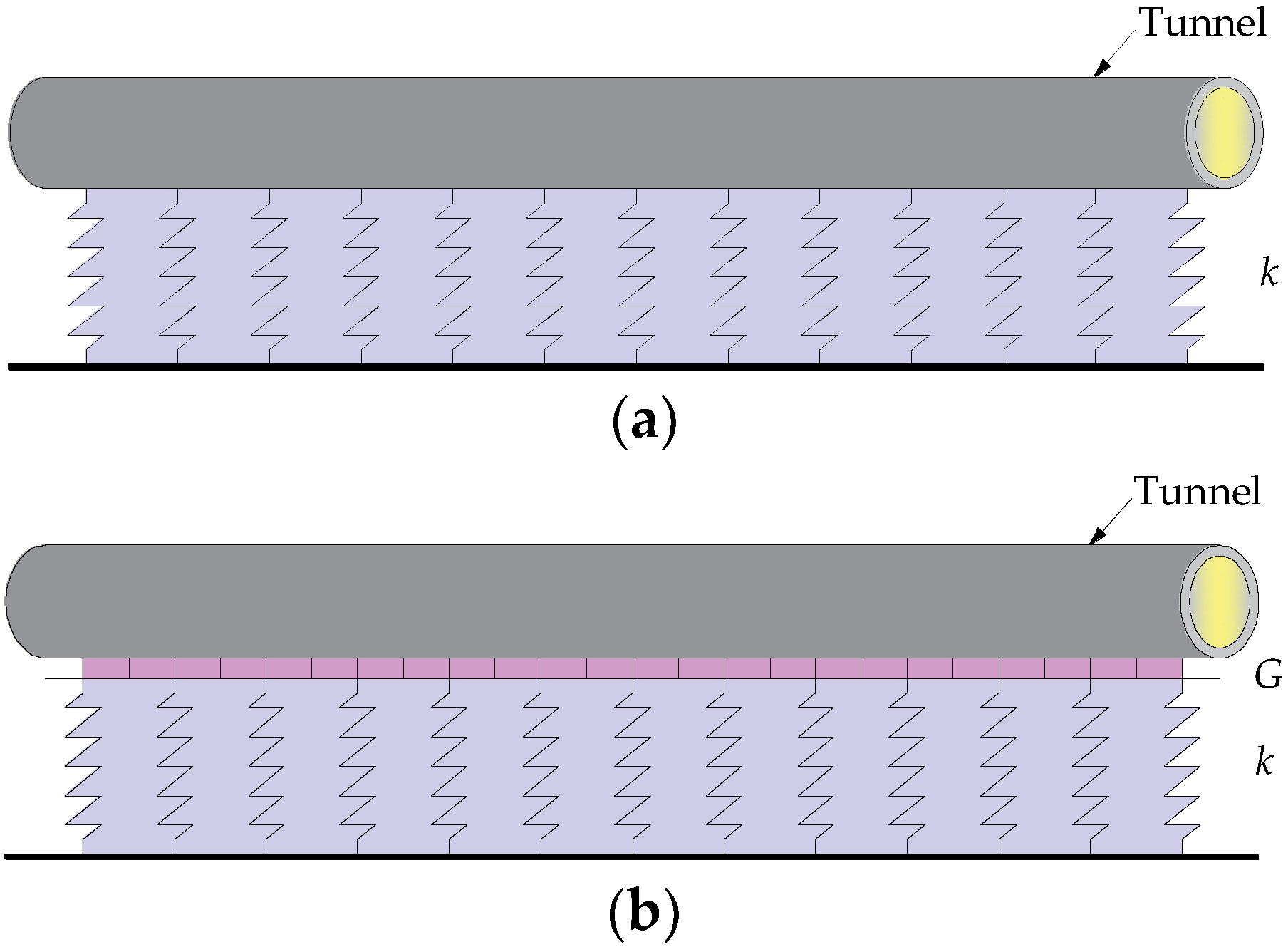
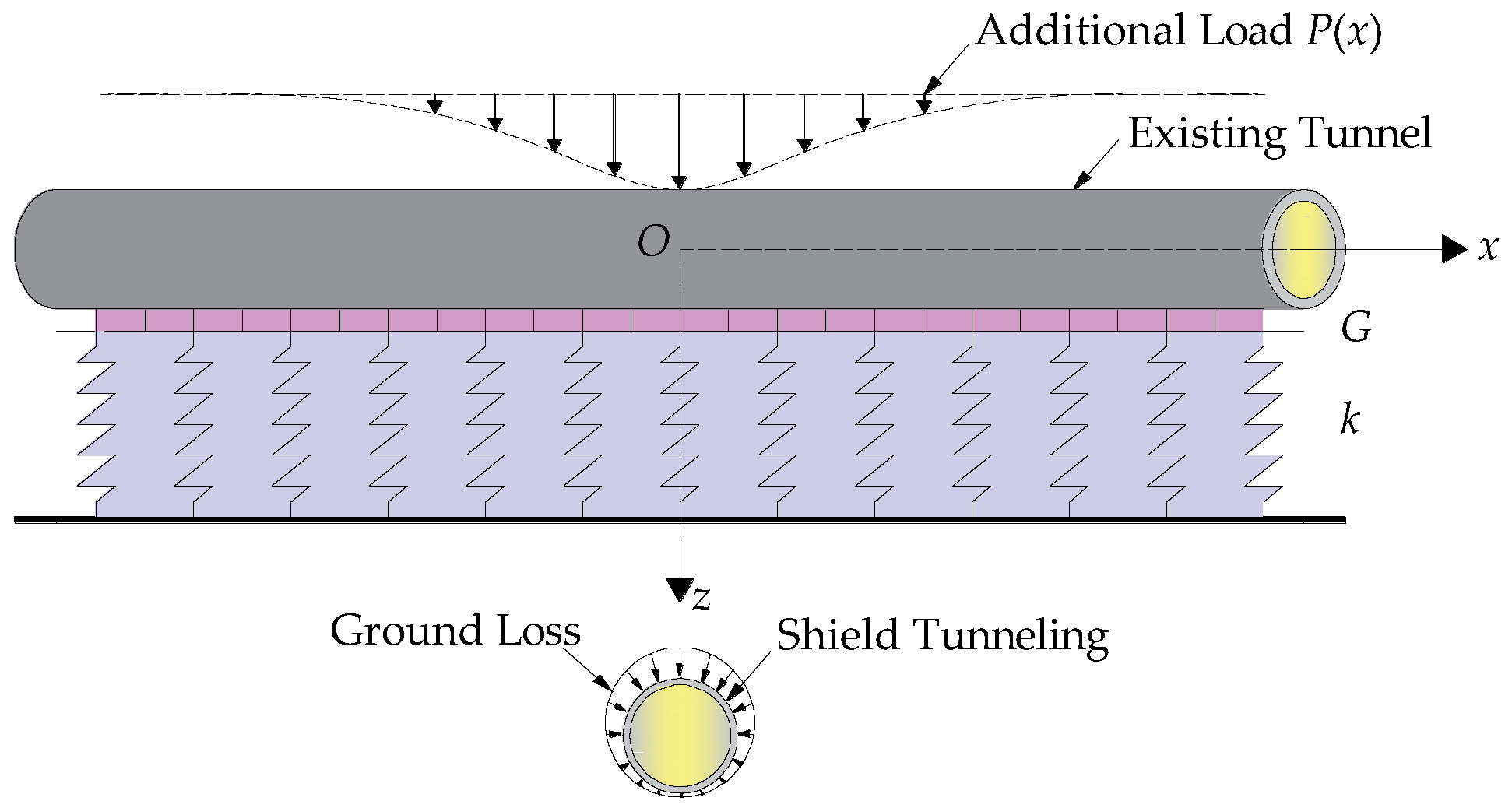
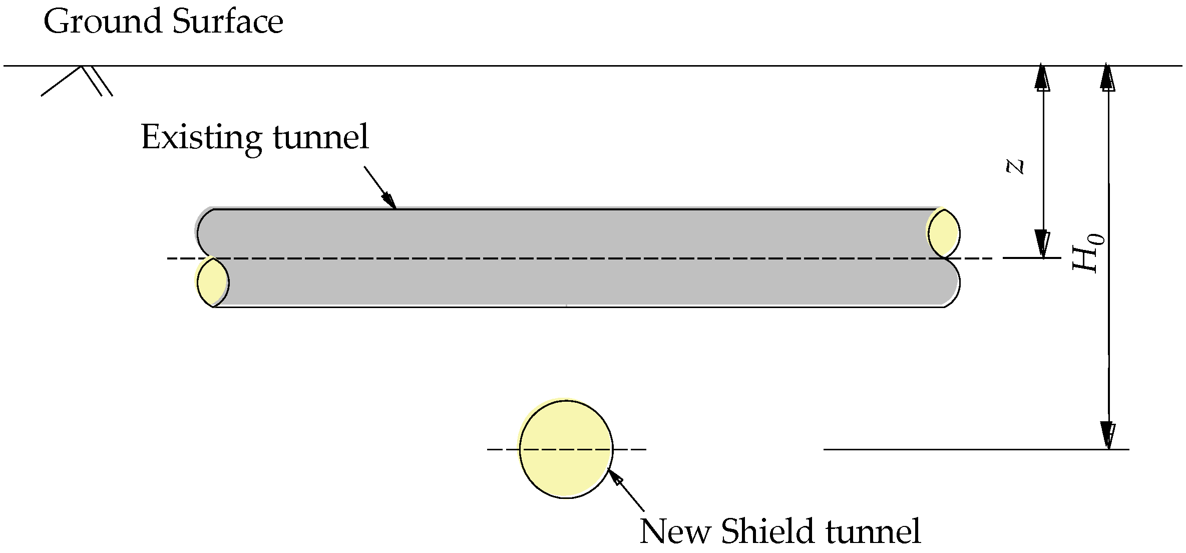
2. Longitudinal Deformation of the Existing Tunnel
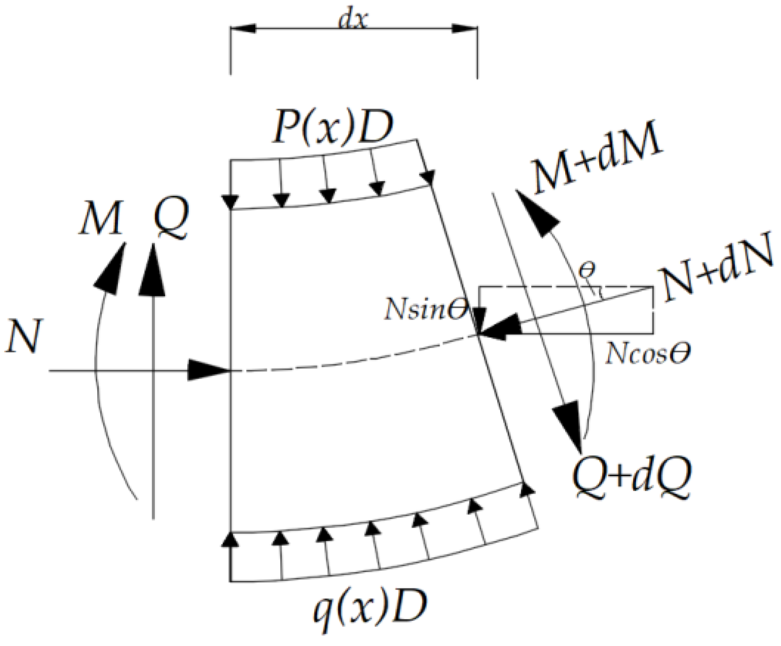
2.1. Governing Differential Equations
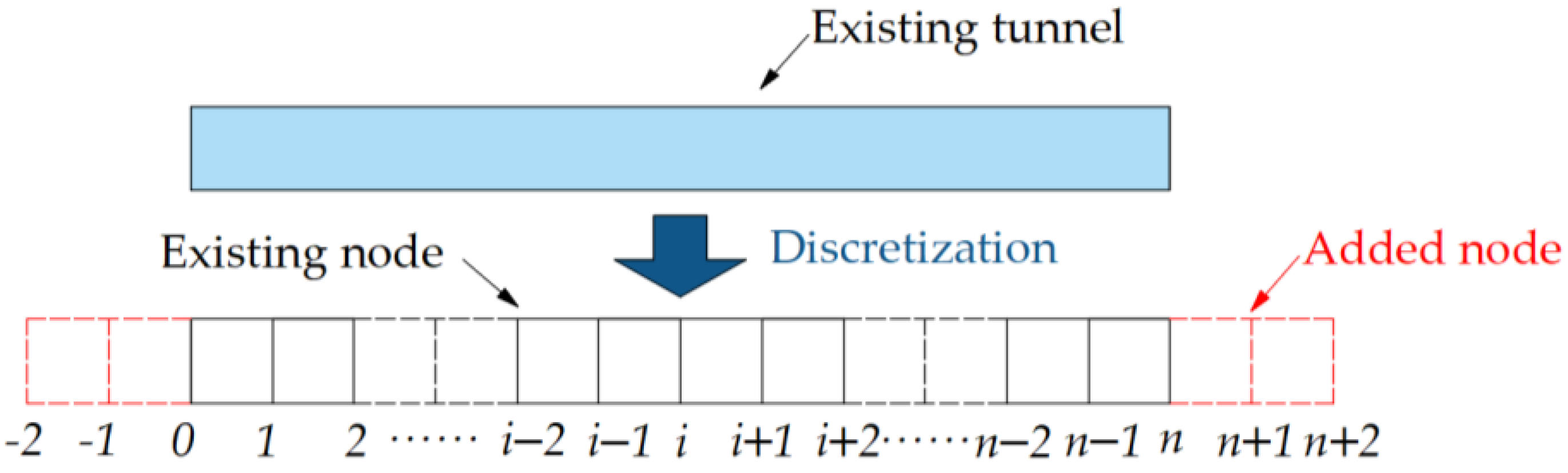
2.2. Derivation of the Solution
2.3. Parameter Determination
3. Results and Discussions
3.1. Case Studies
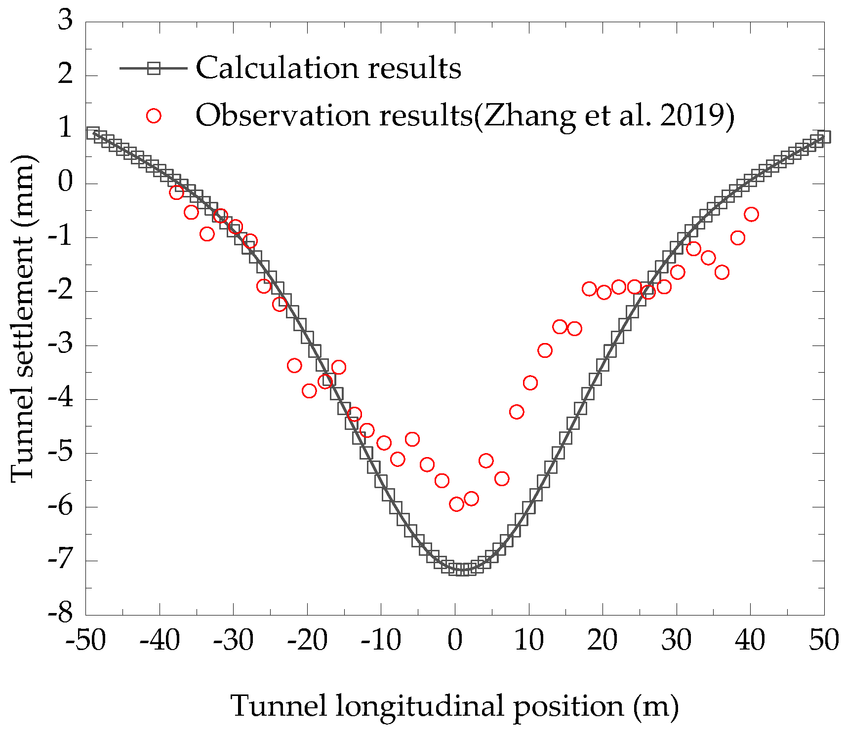
3.1.1. Case 1
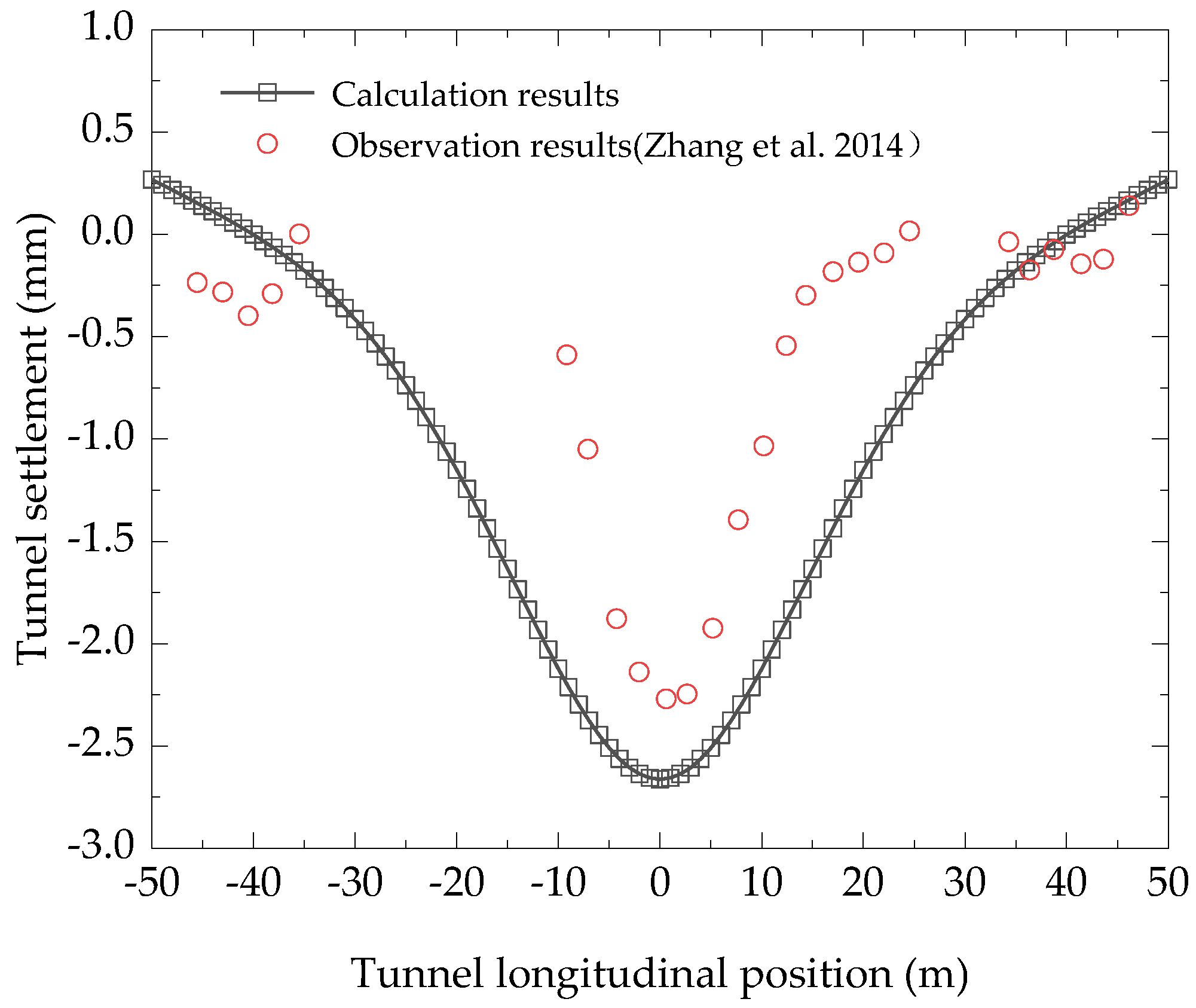
3.1.2. Case 2
3.2. Parametric Analysis
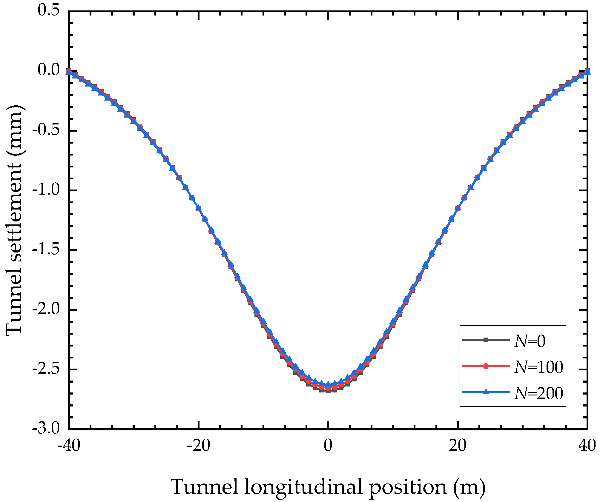
3.2.1. Jacking Force
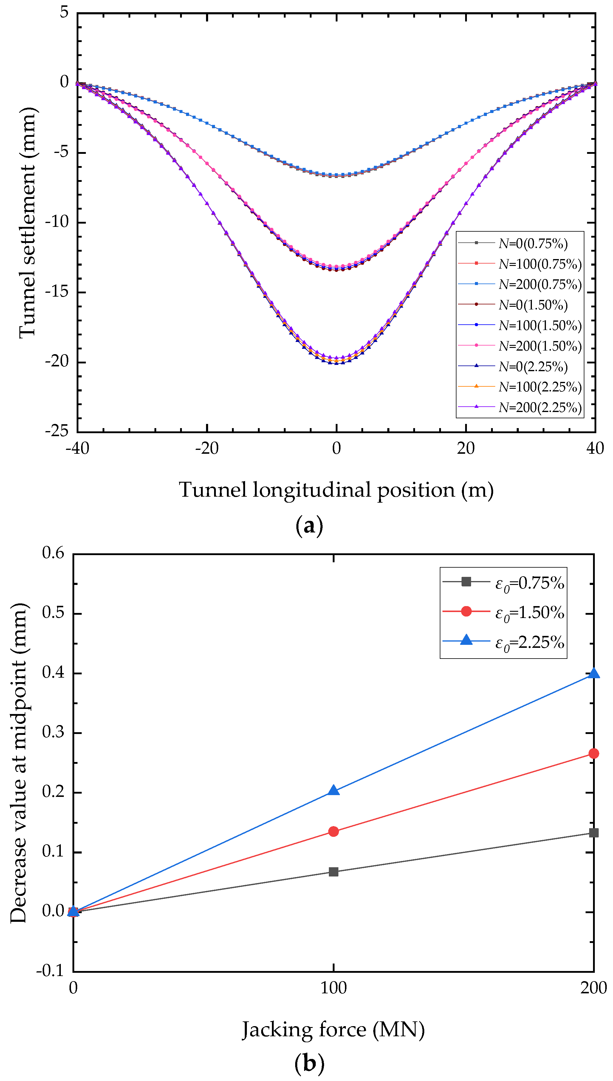
3.2.2. Ground Loss and Jacking Force
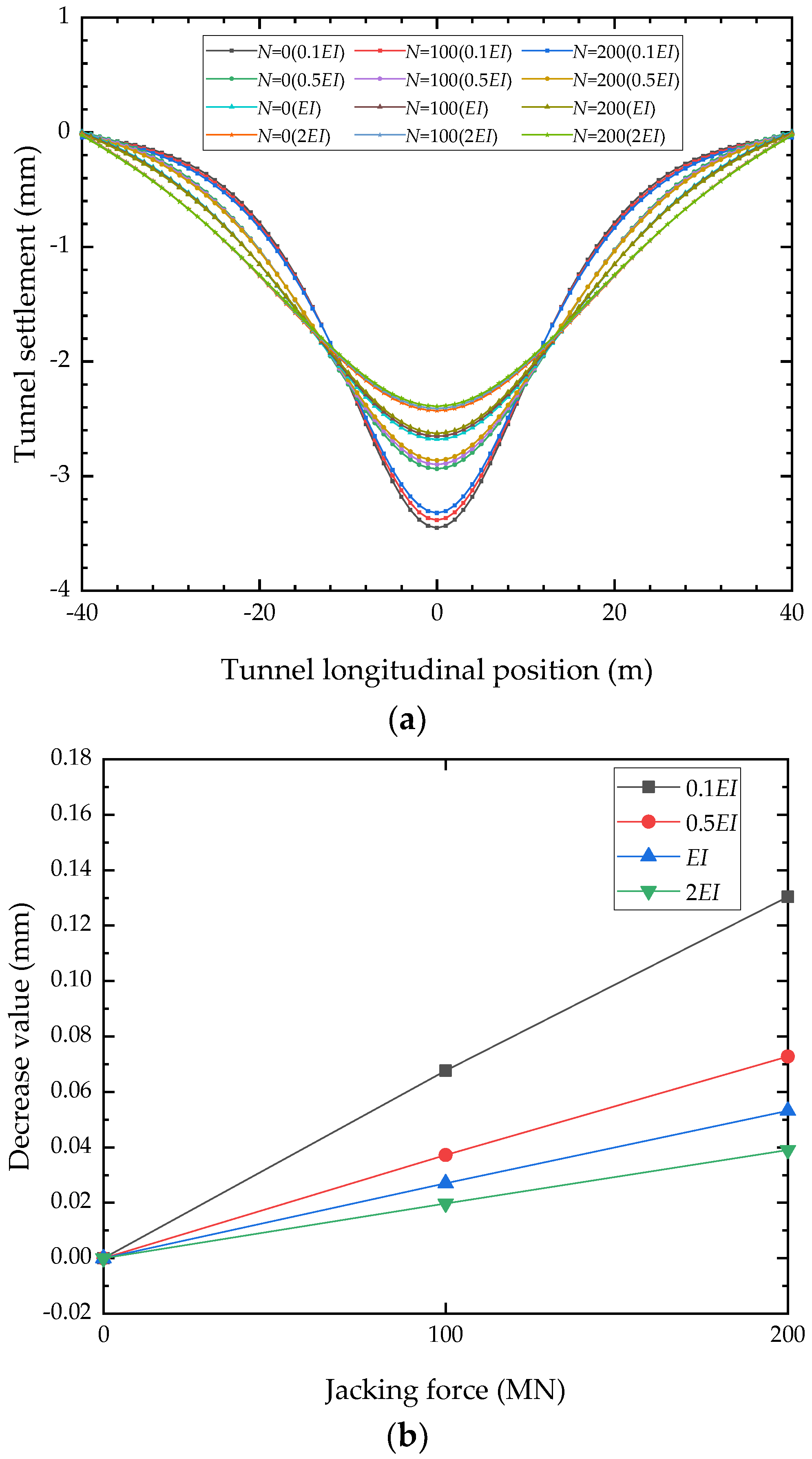
3.2.3. Equivalent Bending Stiffness and Jacking Force
4. Concluding Remarks
Author Contributions
Funding
Data Availability Statement
Conflicts of Interest
References
- Liu, D.; Zuo, J.; Wang, J.; Zhang, T.; Liu, H. Large deformation mechanism and concrete-filled steel tubular support control technology of soft rock roadway—A case study. Eng. Fail. Anal. 2020, 116, 104721. [Google Scholar] [CrossRef]
- Zhang, J.; Zhao, M. Experimental study on mechanical behavior of the skew joints of shield tunnels under large eccentric compressive loading. Tunn. Undergr. Space Technol. 2021, 111, 103876. [Google Scholar] [CrossRef]
- Zhou, Z.; Chen, Y.; Liu, Z.; Miao, L. Theoretical prediction model for deformations caused by construction of new tunnels undercrossing existing tunnels based on the equivalent layered method. Comput. Geotech. 2020, 123, 103565. [Google Scholar] [CrossRef]
- Cheng, H.; Chen, R.; Wu, H.; Meng, F.; Yi, Y. General solutions for the longitudinal deformation of shield tunnels with multiple discontinuities in strata. Tunn. Undergr. Space Technol. 2021, 107, 103652. [Google Scholar] [CrossRef]
- Zheng, G.; Pan, J.; Li, Y.; Cheng, X.; Tan, F.; Du, Y.; Li, X. Deformation and protection of existing tunnels at an oblique intersection angle to an excavation. Int. J. Geomech. 2020, 20, 05020004. [Google Scholar] [CrossRef]
- Liang, L.; Xu, C.; Zhu, B.; Deng, J. Theoretical method for an elastic infinite beam resting on a deformable foundation with a local subsidence. Comput. Geotech. 2020, 127, 103740. [Google Scholar] [CrossRef]
- Liu, X.; Fang, Q.; Zhang, D.; Wang, Z. Behaviour of existing tunnel due to new tunnel construction below. Comput. Geotech. 2019, 110, 71–81. [Google Scholar] [CrossRef]
- Ke, W.; Luo, W.; Fang, T.; Chen, Q.; Xu, C.; Yan, J. A simple closed-form solution for kinematic responses of retaining wall incorporating the effects of shear stiffness of soils. Soil Dyn. Earthq. Eng. 2020, 134, 106163. [Google Scholar] [CrossRef]
- Huang, F.; Zhang, M.; Wang, F.; Ling, T.; Yang, X. The failure mechanism of surrounding rock around an existing shield tunnel induced by an adjacent excavation. Comput. Geotech. 2020, 117, 103236. [Google Scholar] [CrossRef]
- Chen, R.; Chen, S.; Wu, H.; Liu, Y.; Meng, F. Investigation on deformation behavior and failure mechanism of a segmental ring in shield tunnels based on elaborate numerical simulation. Eng. Fail. Anal. 2020, 117, 104960. [Google Scholar] [CrossRef]
- Avgerinos, V.; Potts, D.M.; Standing, J.R. Numerical investigation of the effects of tunnelling on existing tunnels. Geotechnique 2017, 67, 808–822. [Google Scholar] [CrossRef]
- Xue, F.; Zhang, M. Excavation Face Stability of Shield Tunneling Closely Under Existing Tunnels: Particle Flow Simulation. IJST-T Civ. Eng. 2020, 44, 497–506. [Google Scholar] [CrossRef]
- Wang, H.; Liu, W.; Sun, H.; Zhuang, X. Model Test Study on the Influence of Tunnel Construction on Existing Pipeline Under the Condition of Pipeline Leakage. Indian Geotech. J. 2020, 50, 700–709. [Google Scholar] [CrossRef]
- Ng, W.W.C.; Boonyarak, T.; David, M. Effects of Pillar Depth and Shielding on the Interaction of Crossing Multitunnels. J. Geotech. Geoenviron. 2015, 141, 04015021. [Google Scholar] [CrossRef] [Green Version]
- Jin, D.; Yuan, D.; Li, X.; Zheng, H. An in-tunnel grouting protection method for excavating twin tunnels beneath an existing tunnel. Tunn. Undergr. Space Technol. 2018, 71, 27–35. [Google Scholar] [CrossRef]
- Jin, D.; Yuan, D.; Li, X.; Zheng, H. Analysis of the settlement of an existing tunnel induced by shield tunneling underneath. Tunn. Undergr. Space Technol. 2018, 81, 209–220. [Google Scholar] [CrossRef]
- Chen, R.; Lin, X.; Kang, X.; Zhong, Z.; Liu, Y.; Zhang, P.; Wu, H. Deformation and stresscharacteristics of existing twin tunnels induced by close-distance EPBS under-crossing. Tunn. Undergr. Space Technol. 2018, 82, 468–481. [Google Scholar] [CrossRef]
- Winkler, E. Die Lehre von der Elasticitaet und Festigkeit; H. Dominicus: Prague, Czech Republic, 1867. [Google Scholar]
- Liu, X.; Fang, Q.; Zhang, D. Mechanical responses of existing tunnel due to new tunnelling below without clearance. Tunn. Undergr. Space Technol. 2018, 80, 44–52. [Google Scholar] [CrossRef]
- Parsternak, P.L. On a New Method of Analysis of an Elastic Foundation by Means of Two Foundation Constants; Gosudarstvennoe Izdatelstvo Literaturipo Stroitelstvu Arkhitekture: Moscow, Russia, 1954. [Google Scholar]
- Tanahashi, H. Formulas for an infinitely long Bernoulli-Euler beam on the Pasternak model. Soils Found. 2004, 44, 109–118. [Google Scholar] [CrossRef] [Green Version]
- Liu, Z.; Xue, J.F.; Ye, J.Z.; Qian, J. A simplified two-stage method to estimate the settlement and bending moment of upper tunnel considering the interaction of undercrossing twin tunnels. Transp. Geotech. 2021, 29, 100558. [Google Scholar] [CrossRef]
- Li, X.; Zhou, X.; Hong, B.; Zhu, H. Experimental and analytical study on longitudinal bending behavior of shield tunnel subjected to longitudinal axial forces. Tunn. Undergr. Space Technol. 2019, 86, 128–137. [Google Scholar] [CrossRef]
- Liao, S.; Men, Y.; Xiao, M.; Zhang, D. Field tests on longitudinal stress relaxation along shield tunnel in soft ground. Chin. J. Geotech. Eng. 2017, 39, 795–803. [Google Scholar]
- Arnau, O.; Molins, C.; Blom, C.B.M.; Walraven, J.C. Longitudinal time-dependent response of segmental tunnel linings. Tunn. Undergr. Space Technol. 2012, 28, 98–108. [Google Scholar] [CrossRef] [Green Version]
- Huang, Y.; Li, X. An analytic approach for exactly determining critical loads of buckling of nonuniform columns. Int. J. Struct. Stab. Dyn. 2012, 12, 1250027. [Google Scholar] [CrossRef]
- Avcar, M. Elastic Buckling of Steel Columns Under Axial Compression. Am. J. Civil. Eng. 2014, 2, 102–108. [Google Scholar] [CrossRef]
- Ings, N.L.; Trahair, N.S. Beam and column buckling under directed loading. J. Struct. Fire Eng. 1986, 113, 1251–1263. [Google Scholar] [CrossRef]
- Liang, R.; Xia, T.; Huang, M.; Lin, C. Simplified analytical method for evaluating the effects of adjacent excavation on shield tunnel considering the shearing effect. Comput. Geotech. 2017, 81, 167–187. [Google Scholar] [CrossRef]
- Vesic, A.B. Bending of beams resting on isotropic elastic solid. J. Soil Mech. Found. Eng. ASCE 1961, 87, 35–53. [Google Scholar]
- Attewell, P.B.; Yeates, J.; Selby, A.R. Soil Movement Induced by Tunnelling and Their Effects on Pipelines and Structures; Blackie and Son Ltd.: London, UK, 1986. [Google Scholar]
- Yu, J.; Zhang, C.; Huang, M. Soil–pipe interaction due to tunnelling: Assessment of Winkler modulus for underground pipelines. Comput. Geotech. 2013, 50, 17–28. [Google Scholar] [CrossRef]
- Xu, L. Study on the Longitudinal Settlement of Shield Tunnel in Soft Soil. Ph.D. Thesis, Tongji University, Shanghai, China, 2005. [Google Scholar]
- Loganathan, N.; Poulos, H.G. Analytical prediction for tunneling-induced ground movements in clays. J. Geotech. Geoenviron. 1998, 124, 846–856. [Google Scholar] [CrossRef]
- Liang, R.; Zong, M.; Kang, C.; Wu, W.; Fang, Y.; Xia, T. Longitudinal impacts of existing shield tunnel due to down-crossing tunnelling considering shield tunnel shearing effect. J. Zhejiang Univ. Eng. Sci. 2018, 52, 20–430, 472. [Google Scholar]
- Zhang, D.; Huang, Z.; Li, Z.; Zong, X.; Zhang, D. Analytical solution for the response of an existing tunnel to a new tunnel excavation underneath. Comput. Geotech. 2019, 108, 197–211. [Google Scholar] [CrossRef]
- Zhang, Z.; Huang, M. Geotechnical influence on existing subway tunnels induced by multiline tunneling in Shanghai soft soil. Comput. Geotech. 2014, 56, 121–132. [Google Scholar] [CrossRef]
- Wu, C.; Zhu, Z. Statistical analysis of ground loss ratio caused by different tunnel construction methods in China. J. Zhejiang Univ. Eng. Sci. 2019, 53, 19–30. [Google Scholar]
- Huang, H.; Xu, L.; Yan, J.; Yu, Z. Study on transverse effective rigidity ratio of shield tunnels. Chin. J. Geotech. Eng. 2006, 28, 11–18. [Google Scholar]


| Case | Tunnel | Buried Depth (m) | Diameter (m) | Lining Thickness (m) |
|---|---|---|---|---|
| 1 | New | 20.1 | 6.2 | 0.35 |
| Existing | 9.1 | 6.2 | 0.35 | |
| 2 | New | 25.1 | 6.2 | 0.35 |
| Existing | 17.1 | 6.2 | 0.35 |
Publisher’s Note: MDPI stays neutral with regard to jurisdictional claims in published maps and institutional affiliations. |
© 2022 by the authors. Licensee MDPI, Basel, Switzerland. This article is an open access article distributed under the terms and conditions of the Creative Commons Attribution (CC BY) license (https://creativecommons.org/licenses/by/4.0/).
Share and Cite
Liu, T.; Jiang, X.; Luo, W.; Yan, J. Settlement of an Existing Tunnel Induced by Crossing Shield Tunneling Involving Residual Jacking Force. Symmetry 2022, 14, 1462. https://doi.org/10.3390/sym14071462
Liu T, Jiang X, Luo W, Yan J. Settlement of an Existing Tunnel Induced by Crossing Shield Tunneling Involving Residual Jacking Force. Symmetry. 2022; 14(7):1462. https://doi.org/10.3390/sym14071462
Chicago/Turabian StyleLiu, Tianyu, Xuehui Jiang, Wenjun Luo, and Jianwei Yan. 2022. "Settlement of an Existing Tunnel Induced by Crossing Shield Tunneling Involving Residual Jacking Force" Symmetry 14, no. 7: 1462. https://doi.org/10.3390/sym14071462