Article

Model-Free Predictive Power Control for PWM Rectifiers under Asymmetrical Grids

1
Inverter Technologies Engineering Research Center of Beijing, North China University of Technology, Beijing 100144, China
2
School of Electrical and Electronic Engineering, North China Electric Power University, Beijing 102206, China
*
Author to whom correspondence should be addressed.
These authors contributed equally to this work.
Symmetry 2022, 14(6), 1224; https://doi.org/10.3390/sym14061224
Submission received: 29 March 2022 / Revised: 30 May 2022 / Accepted: 11 June 2022 / Published: 13 June 2022
(This article belongs to the Section Engineering and Materials)

Abstract

:
Conventional model predictive power control (MPPC) features a simple concept and quick dynamic response. However, it relies heavily on the system model and its parameter accuracy. Furthermore, the steady ripples are still high due to the use of one voltage vector during one control period. Recently, model-free predictive current control (MFPCC) has been proposed in the current control of PWM rectifiers. Despite the strong parameter robustness, the principle of MFPCC cannot be directly applied to power control, because the relationship between power and converter voltage is more complex. This paper first proposes a basic model-free predictive power control (MFPPC), which successfully extends the principle of MFPCC to power control. Subsequently, an improved MFPPC is proposed, which uses an extended finite control set of voltage vectors to improve the steady-state performance. Furthermore, by using the online updated ultralocal model of PWM rectifiers, the problem of stagnant power updating in basic MFPPC is solved. The ideal three-phase grid voltages are symmetrical and sinusoidal, but the actual grids are usually unsymmetrical. In this paper, the proposed method is extended to asymmetrical power grids by adding an appropriate compensated power to the original power references. The proposed basic MFPPC and improved MFPPC are compared to conventional MPPC. The presented experimental results confirm the effectiveness of the proposed methods.

1. Introduction

Compared to conventional diode rectifiers, three-phase pulse-width-modulated (PWM) rectifiers have many advantages, such as bidirectional power flow, decoupled control of active power and reactive power, sinusoidal grid currents, and good DC-link voltage regulation ability [1]. In recent years, many scholars have carried out extensive research on the high-performance control of PWM rectifiers in industrial fields.
As a widely used control method, voltage oriented control (VOC) [2] can obtain good steady-state performance, but it requires some tuning work due to the use of a proportional integral (PI) controller, and the dynamic performance is not ideal. Direct power control (DPC) [3,4] is based on instantaneous power theory by selecting appropriate vectors to directly control active power and reactive power, which features a very quick dynamic response. However, the control performance depends on the accuracy of the vector table and has a large steady-state ripple. Model predictive control (MPC) can achieve better steady-state performance than DPC and similar quick dynamic response to DPC, so it has attracted wide attention [5,6]. Different from the switching table in DPC, MPC uses a cost function, which is usually defined as the power error between the reference value and predicted value, to select the best voltage vector. As a result, the selected voltage vector is more accurate and effective than DPC [7]. However, MPC relies on an accurate system model and parameters to predict the future behaviors of the concerned variables. When there are parameter mismatches caused by the working condition, the control performance may deteriorate. Furthermore, the steady-state performance still needs to be improved due to the limited number of basic voltage vectors in the two-level converter.
To solve the problem of parameter dependence, scholars put forward disturbance-observer-based control [8], which includes the Luenberger disturbance observer [9], extended state observer (ESO) [10], sliding mode observer, and so on. The disturbance observer can observe the disturbance caused by parameter changes in real time and add the observed disturbance to the original control algorithm to compensate for the error caused by the disturbance. References [9,11], respectively, apply the Luenberger disturbance observer and the ESO to a PWM rectifier to compensate the errors caused by parameter perturbation in real time, resulting in favorable robustness.
There are also some control methods that have been extensively studied because they are insensitive to system parameter changes, such as sliding mode control [12], adaptive control [13], and model-free control (MFC) [14,15,16,17]. MFPCC is a popular control method based on current differences by combining MFC and predictive control [15,17]. In [14], the MFPCC method uses only the difference between the stator current and the current in the past to achieve current prediction without using motor parameters. However, the prediction accuracy of MFPCC may be affected if a certain voltage vector is not applied for a relatively long period, which is called stagnant current updating. In this way, the stored current difference is not updated in a timely manner and would cause prediction error. To solve the problem of stagnant current variation update, various methods have been proposed in the literature. For example, in [17], the grid current variation is calculated from four estimated variables without using a lookup table. As these four variables are calculated in each control period, the stagnant current variation update is removed. However, so far, most of the MFC methods in existing papers are based on current control and cannot be directly used for power control, as shown in this paper.
Another kind of MFC method is based on an ultralocal model [18]. The uncertain term of the ultralocal model can be obtained by the differential algebra method [18] and ESO [19]. However, most of the MFC methods based on the ultralocal model assume that the gain of the input is at least roughly known, and the tuning work is generally unavoidable.
Generally, the consumer using direct current is not directly connected to the AC grid, but through a converter, such as a PWM rectifier in this paper. There are many more types of AC loads connected to the network, and these AC loads are the main source of gird imbalance. The single-phase load, grid faults, voltage dip, and so on, are possible factors for the grid imbalance. This is a common phenomenon for the three-phase network, especially in rural areas equipped with weak grids. This may cause current distortion and twice grid-frequency power fluctuations, if the control method developed for ideal grid voltages is directly used in the PWM rectifier [1]. Scholars have proposed various methods to eliminate the undesirable effects caused by nonideal power grids [20]. The prior methods were usually based on VOC and require much tuning work due to the additional PI controllers [21]. Recently, the power compensation technique was proposed [22], which is especially suitable for DPC [4] and MPC [6] with complex power as control variables. By simply adding the power compensation to the original power reference without modifying the internal structure, various control targets can be realized [23], such as sinusoidal and symmetrical grid currents, active power ripple cancellation, and reactive power cancellation.
This paper proposes two MFPPC methods to achieve accurate and robust power control for PWM rectifiers, even under the condition of unsymmetrical grids. The main contributions of this paper are threefold. Firstly, the principle of MFPCC based on current difference detection is successfully extended to MFPPC, which uses an improved complex power variable. In this way, the proposed basic MFPPC inherits the quick response and simple principle of the conventional MPPC method and provides strong robustness similar to that of the conventional MFPCC method. Secondly, to further improve the control accuracy, this paper proposes an improved MFPPC method based on a reconstructed ultralocal model. It is updated by using the improved complex power, which is calculated by the grid voltage and current of the past control period. Therefore, the gain of the input voltage and the uncertainty of the system are estimated and updated in each control period. According to this updated ultralocal model and by using an extended set of voltage vectors, the optimal voltage vector is obtained by cost function evaluation to achieve further power error minimization. Finally, by compensating the power reference value under the unsymmetrical power grid, the proposed methods achieve three control targets, including sinusoidal and symmetrical grid currents, active power ripple cancellation, and reactive power cancellation. These three control targets can be easily achieved by tuning a gain in the universal expression of compensated power. The experimental results are presented to validate the effectiveness of the proposed method.

2. Conventional MPPC Based on Accurate Model

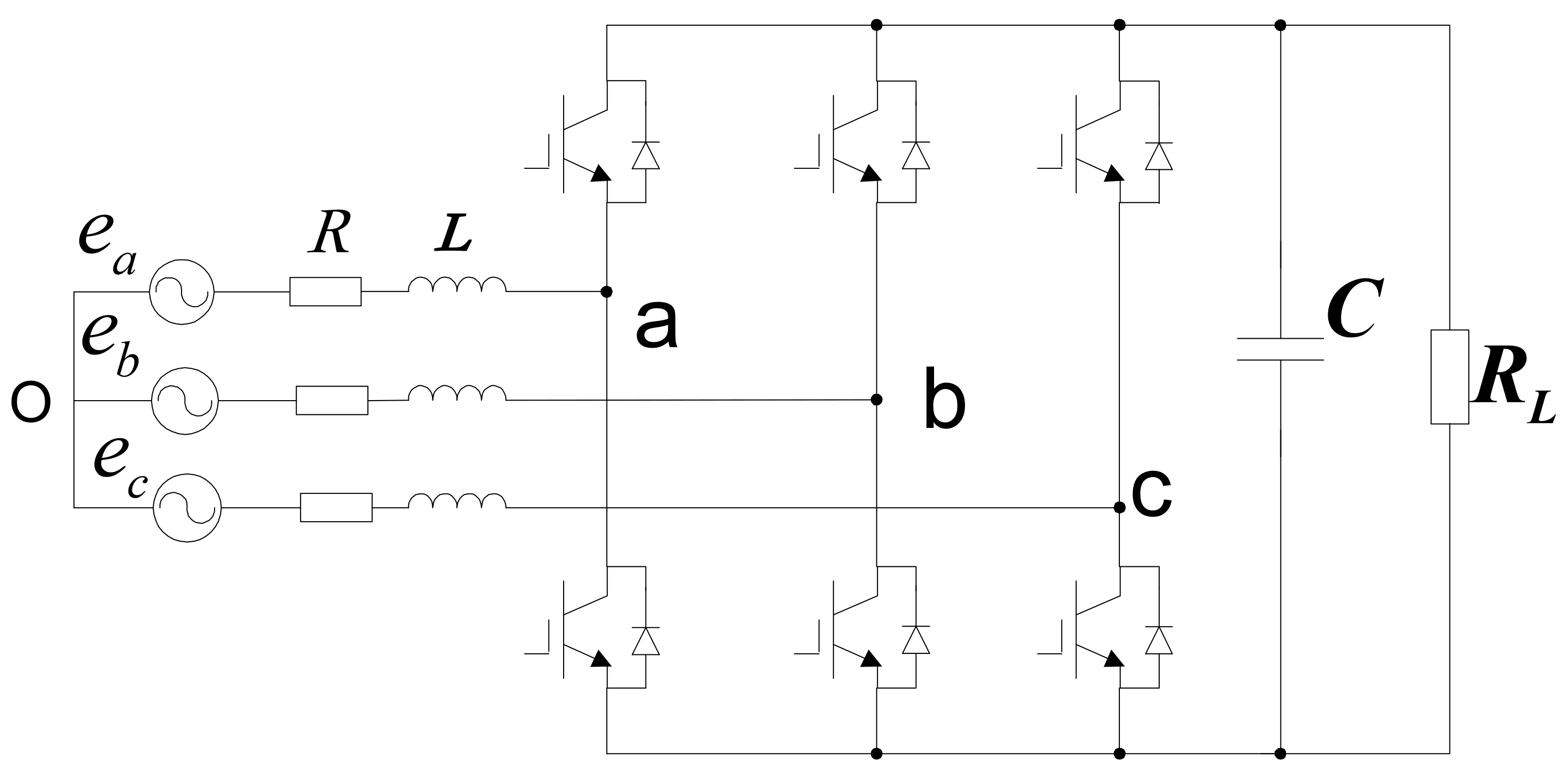
2.1. Accurate Mathematical Model

Figure 1 shows the topology of a two-level three-phase PWM rectifier, where R, L, C, and R L indicate the resistance of the input filter, the inductor of the input filter, the DC-side capacitor, and the load resistor, respectively.
The three-phase system can be expressed concisely using complex vectors [24]. In this paper, the mathematical model of the PWM rectifier in a two-phase stationary frame is expressed using the complex vector as [6]:
e = R i + L d i d t + v
where e , i , and v are the grid voltage vector, the grid current vector, and the rectifier voltage vector, respectively.
According to instantaneous power theory [25], the complex power on the grid side can be computed as:
S = 3 2 i e = P + j Q
where P = Re ( S ) and Q = Im ( S ) represent the active power and reactive power, respectively, and i represents the conjugate of the grid current vector.
According to (1), the derivative of the grid current can be obtained as
d i d t = 1 L e v R i
Under the symmetrical and sinusoidal grid voltage conditions, the derivative of the grid voltage is expressed as:
d e d t = j ω | e | e j ω t = j ω e
According to (2)–(4), the derivative of the complex power can be obtained as [6]:
d S d t = 1 L 3 2 | e | 2 v * e R j ω L S

2.2. Conventional MPPC

In the conventional MPPC method [6], the cost function is defined as the absolute value of the power error, and it is expressed as:
g = | S r e f S k + 2 |
where S r e f = P r e f + j * Q r e f , with P r e f being the active power reference value and Q r e f being the reactive power reference value. P r e f is obtained from the outer DC voltage loop using a proportional integral (PI) regulator. To achieve an instantaneous power factor operation of the system, the reactive power reference value Q r e f was set to zero. In addition, S k + 2 is the complex power at the k + 2 th instant, and its calculation is as follows.
According to Formula (2), the complex power S k + 1 at the k + 1 th instant can be obtained as follows:
S k + 1 = 3 2 i k + 1 * e k + 1
where the grid voltage and current at the k + 1 th instant are
e k + 1 = e j ω T s c e k 1 + j ω T s c e k
i k + 1 = i k + T s c L e k v k R i k
and T s c is the sampling period.
The complex power at the k + 2 th instant considering one-step delay compensation is calculated as follows:
S k + 2 = S k + 1 + T s c L ( 3 2 ( | e k + 1 | 2 v k + 1 * e k + 1 ) ( R j ω L ) S k + 1 )
It can be seen from Formula (10) that the prediction of complex power is dependent on the system model and parameter accuracy. In practical applications, the model uncertainty and parameter variations caused by temperature and working condition may affect the prediction accuracy and the control performance.

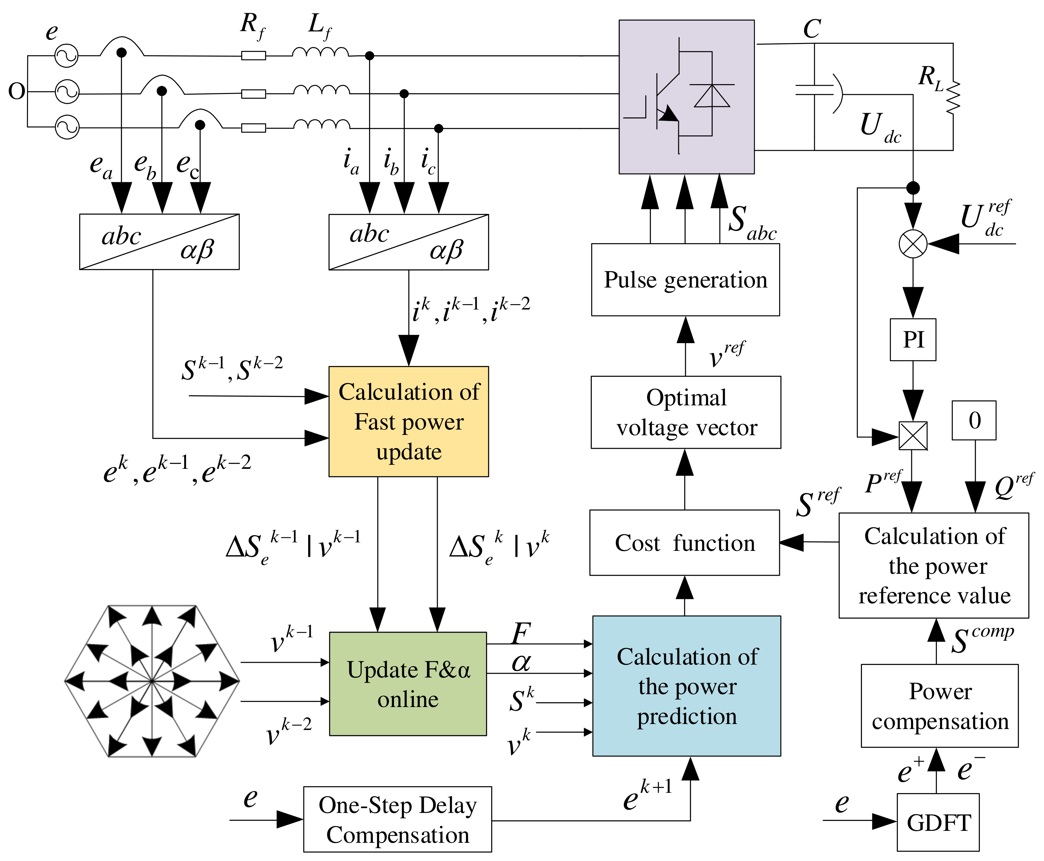
3. Proposed MFPPC Based on Ultralocal Model

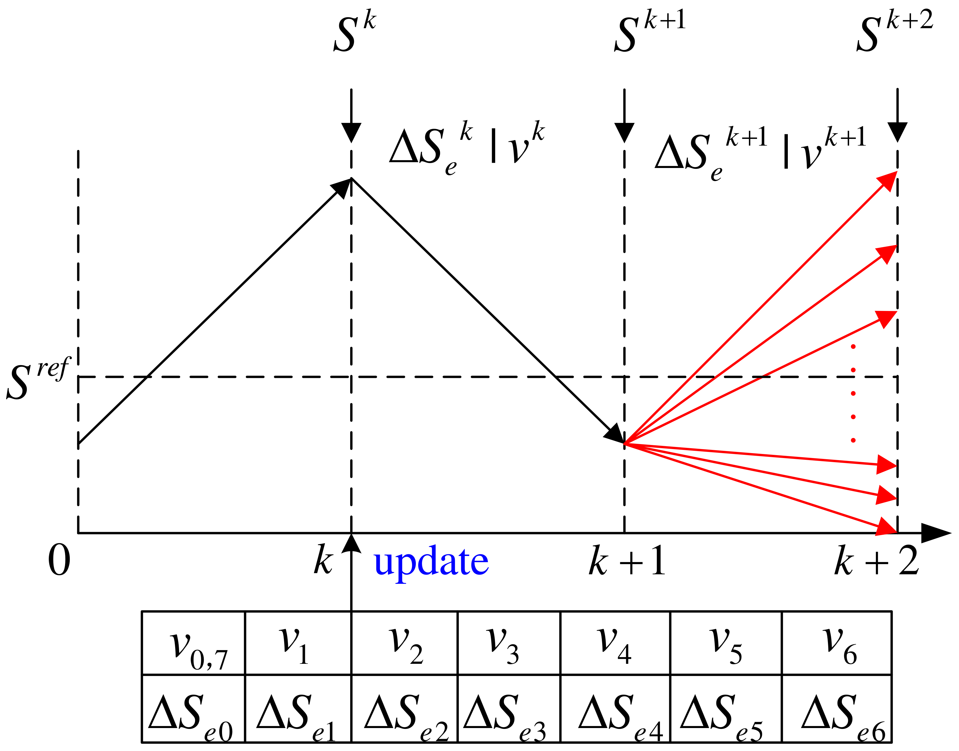
3.1. Principle of the Proposed Basic MFPPC

The conventional MFPCC has been successfully validated in the current control of the PWM rectifier [15], where the current difference corresponding to various voltage vectors is stored and used in the stage of current prediction. The lookup table storing the current differences is updated at each sampling instant when the measured current is available. In this paper, the principle in [15] is firstly reproduced and applied for the power control of the PWM rectifier. By storing the power difference under different voltage vectors at the previous moment, the complex power difference in the k th and k + 1 th sampling periods is expressed as:
Δ S k | v k = S k + 1 S k Δ S k + 1 | v k + 1 = S k + 2 S k + 1
where S k , S k + 1 , and S k + 2 represent the complex power calculated at the k th , k + 1 th , and k + 2 th instant, respectively. Here, v k is the voltage vector applied between the k th instant and the k + 1 th instant, and v k + 1 is the voltage vector applied between the k + 1 th instant and the k + 2 th instant.
According to Formula (11), the complex power S k + 1 at the k + 1 th instant is predicted as
S k + 1 = S k + Δ S k | v k
where Δ S k | v k is obtained from the lookup table storing the complex power difference corresponding to v k .
Taking into account the one-step delay in the digital system, the complex power S k + 2 at the k + 2 th instant can be obtained from (11) and (12) as
S k + 2 = S k + 1 + Δ S k + 1 | v k + 1 = S k + Δ S k | v k + Δ S k + 1 | v k + 1
where Δ S k + 1 | v k + 1 is obtained from the lookup table storing the complex power difference corresponding to v k + 1 .
However, the conventional MFPPC method using (12) and (13) cannot work stably, because the complex power is not only affected by the applied voltage vector, but also related to the grid voltages. Figure 2a shows the simulation results for conventional MFPPC using (12) and (13). It is seen that both active power and reactive power cannot track the reference value and the system is unstable. The main reason is that the power is not only affected by the converter voltage vector, but also the grid voltage vector, as shown in (5).
To solve the problem of the poor control performance of the conventional MFPPC method, this paper proposes a basic MFPPC method based on an improved complex power difference. This improved complex power difference is defined as
Δ S e = Δ S / e
which is different from the conventional power difference in (11) by considering the influence of the grid voltage vector.
Combining (11) and (14), the improved complex power of the corresponding voltage vector can be obtained as
Δ S e k | v k = Δ S k | v k e k Δ S e k + 1 | v k + 1 = Δ S k + 1 | v k + 1 e k + 1
Therefore, the complex power S k + 2 at the k + 2 th instant can be predicted from (13) and (15) as
S k + 2 = S k + 1 + Δ S e k + 1 | v k + 1 e k + 1 = S k + Δ S e k | v k e k + Δ S e k + 1 | v k + 1 e k + 1
where Δ S e k | v k and Δ S e k + 1 | v k + 1 are the improved complex power differences corresponding to v k and v k + 1 , respectively.
Formula (16) indicates that, compared with Formula (10), which needs the accurate system model and parameters to predict the complex power, the power prediction in the proposed basic MFPPC method is only related to the improved power difference. Therefore, the proposed basic MFPPC has good parameter robustness. The improved power differences corresponding to different voltage vectors are stored in a lookup table and used in the stage of complex power prediction, as shown in Figure 3. At the k th instant, the complex power can be calculated from the measured grid voltages and currents. Meanwhile, the improved complex power corresponding to the voltage vector applied between k 1 th and k th is updated in the lookup table. The complex power at k + 2 th is predicted according to (16) by finding the improved complex power stored in the lookup table for the same voltage vector. The simulation results of the proposed basic MFPPC method using improved complex power difference are shown in Figure 2b. Compared to the results in Figure 2a for conventional MFPPC, the proposed basic MFPPC can achieve accurate power control and the system is stable, validating the effectiveness of the proposed method.

3.2. Principle of Proposed Improved MFPPC

Although the proposed basic MFPPC achieves accurate power control, there are still irregular spikes in the active power, as shown in Figure 2b. This phenomena is similar to that in conventional MFPCC [14,15], which is mainly related to the stagnant updating of stored current or power differences. To solve the problem of update stagnation in the proposed basic MFPPC method, this paper proposes an improved MFPPC method with fast power difference updating based on the ultralocal model.
The ultralocal model of the PWM rectifier in a two-phase stationary frame can be obtained as [18]
d S d t = F + α v *
where F represents the unknown parts of the system and possible disturbances and α is the gain of the input. Generally, F can be estimated using the differential algebra method [18] and ESO [19]. However, these methods are relatively complicated and require some tuning work. Furthermore, the gain α is assumed to be roughly known or obtained based on empirical experience. This makes the use of the ultralocal model not universal in practical applications.
The proposed improved MFPPC method combines the ultralocal model with the idea of the improved power difference to effectively avoid the influence of the parameter inaccuracy of the PWM rectifier. Through the estimation of the α and F parts in the ultralocal model of a PWM rectifier, the improved power difference information corresponding to all voltage vectors can be updated in each control period. On the contrary, in the proposed basic MFPPC, only one improved power difference can be updated.
To obtain the estimation of α and F , the complex power values at the ( k 2 ) th , ( k 1 ) th , and ( k ) th instants need to be recorded. According to (2) and (15), the improved complex at the ( k 2 ) th and ( k 1 ) th instances is expressed as follows:
Δ S e k 1 = 3 2 i k * e k i k 1 * e k 1 e k 1 Δ S e k 2 = 3 2 i k 1 * e k 1 i k 2 * e k 2 e k 2
where i k , i k 1 , and i k 2 represent the grid current detected at the ( k ) th , ( k 1 ) th and ( k 2 ) th instants, respectively. In addition, e k , e k 1 , and e k 2 represent the grid voltage detected at the ( k ) th , ( k 1 ) th , and ( k 2 ) th instant, respectively.
According to (17) and (18), the proposed complex power difference in the k 1 th and k 2 th sampling periods can be calculated as follows:
Δ S e k 1 T s c = F k + α v k 1 , * Δ S e k 2 T s c = F k 1 + α v k 2 , *
where F k and F k 1 are considered to be approximately equal because of the high sampling frequency.
Solving (19), α can be calculated as follows:
α = Δ S e k 1 Δ S e k 2 T s c v k 1 , * v k 2 , *
By substituting (20) into (19), F can be obtained as follows:
F = Δ S e k 1 T s c α v k 1 , *
After obtaining α and F in the ultralocal model of (17), the complex power prediction S k + 2 at the k + 2 th instant can be obtained from (7), (20), and (21) as:
S k + 2 = S k + 1 + F + α v k + 1 , * T s c e k + 1
Compared to the power prediction in (16) of the proposed basic MFPPC, the power prediction in (22) is more accurate and timely, because both α and F are online updated in each control period, which solves the problem of stagnant update in the proposed basic MFPPC. However, as only one voltage vector is applied during one control period, the steady-state performance is still not satisfactory. To improve the steady-state performance of the proposed basic MFPPC, this paper adopts an extended finite control set including 20 voltage vectors rather than 8 voltage vectors in the basic MFPPC. Figure 4 shows the 20 voltage vectors, which include 8 basic voltage vectors and 12 synthesized voltage vectors. These 20 voltage vectors are listed in Table 1.
After obtaining the predicted value of the complex power by using (22), the next step is to find the optimal voltage vector among the 20 voltage vectors in the proposed MFPPC to minimize the cost function in (6). This part is the same as in conventional MPPC except that the voltage vector evaluation is 20 instead of 8. The control diagram of the proposed MFPPC is shown in Figure 5.

3.3. Operation under Unsymmetrical Grid Conditions

Under actual working conditions, the power grid voltage is often asymmetrical due to load asymmetry, power grid failure, and other factors. This is a common phenomenon for the three-phase network, especially in rural areas equipped with weak grids. To make the proposed method in this paper universal and versatile, three control targets are considered. The targets I, II, and III are sinusoidal and symmetrical grid currents, active power ripple cancellation, and reactive power cancellation, respectively.
The three-phase PWM rectifier is a three-wire connection system. Hence, the zero sequences of both three-phase grid voltages and currents are always zero [26]. Hence, the grid voltage under asymmetrical grid conditions can be expressed as
e = e + + e
where e + and e represent the positive and negative sequence components of the grid voltage, respectively. The positive and negative sequences component of the grid voltage under an unsymmetrical grid conditions are extracted by the generalized discrete Fourier transform (GDFT) harmonic extraction method [27], which has the ability to suppress the low-order harmonics. Hence, the proposed method is also effective even if there are some low-order harmonics, namely unbalanced and distorted grid voltages. It should be noted that the decomposition of the positive/negative sequence component for voltage e is only applied in the stage of power compensation to achieve various control targets, which acts in the outer control loop, as shown in the bottom right of Figure 5. In the internal control loop, to achieve fast and accurate tracking of the power references, the real-time value of voltages and currents (including α -axis and β -axis components) should be used.
Following the principle of power compensation in [22], the power compensation for each control target is summarized in Table 2 [23]. By analyzing the three power compensation expression, a unified power compensation can be obtained as follows:
S c o m p = 2 k · Re e e + S r e f + j · 2 ( 1 k ) · Im e e + S r e f
where k ( 0 k 1 ) represents a coefficient, which can be adjusted to achieve different control targets. k = 0.5 achieves target I, k = 0 target II, and k = 1 target III. After that, the new power reference value is obtained by adding the power compensation value to the original power reference value.

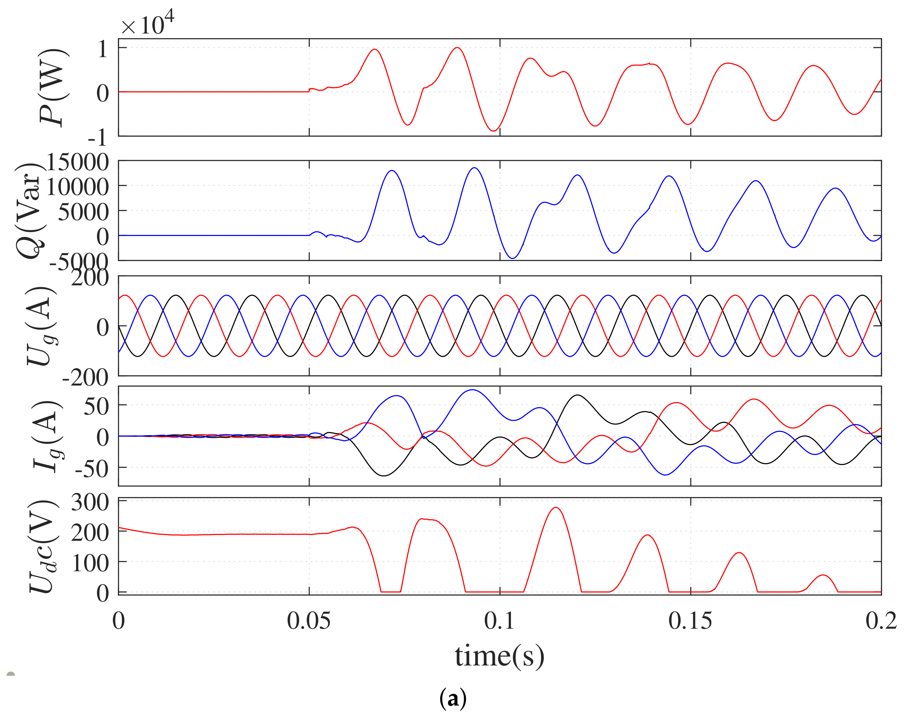
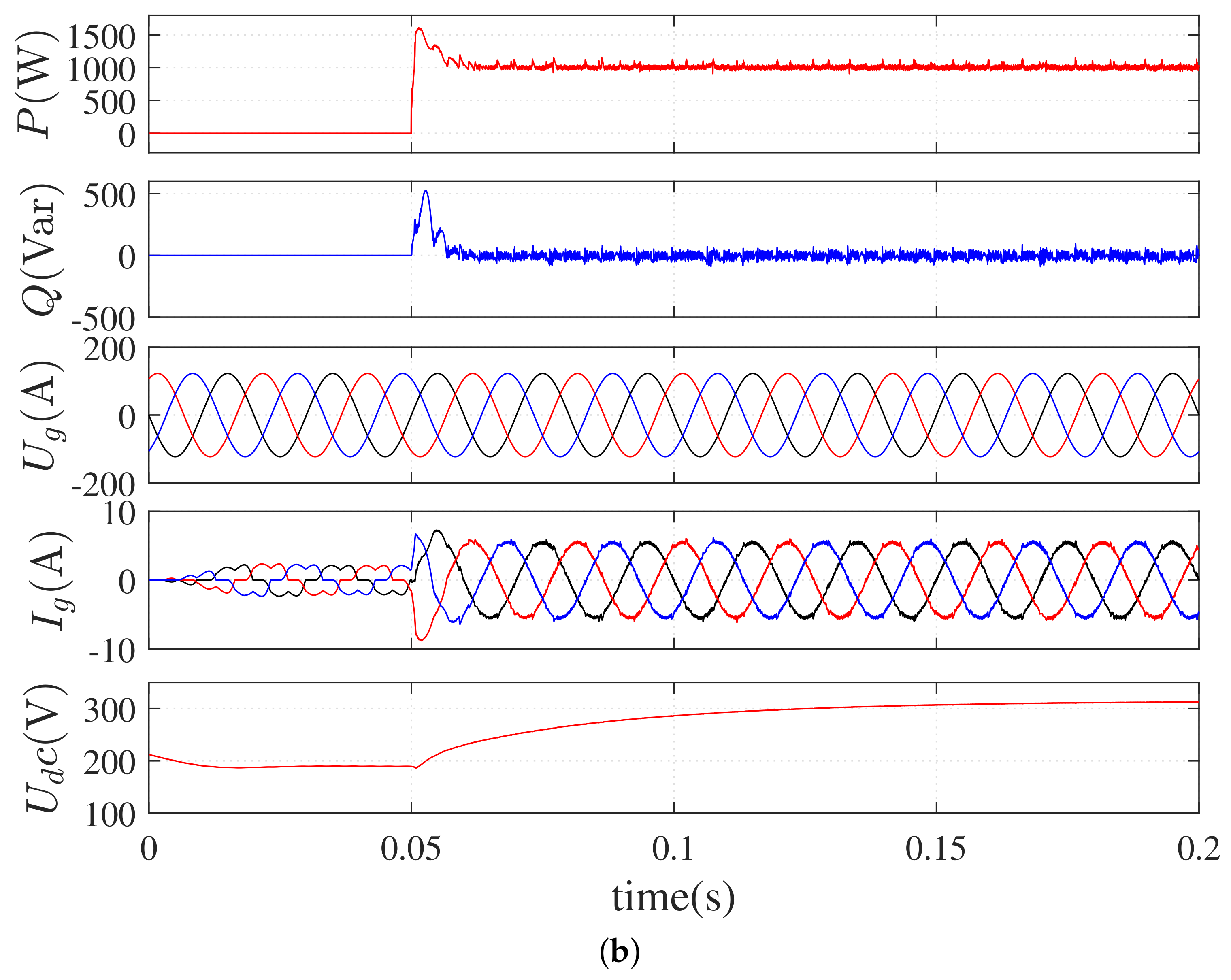
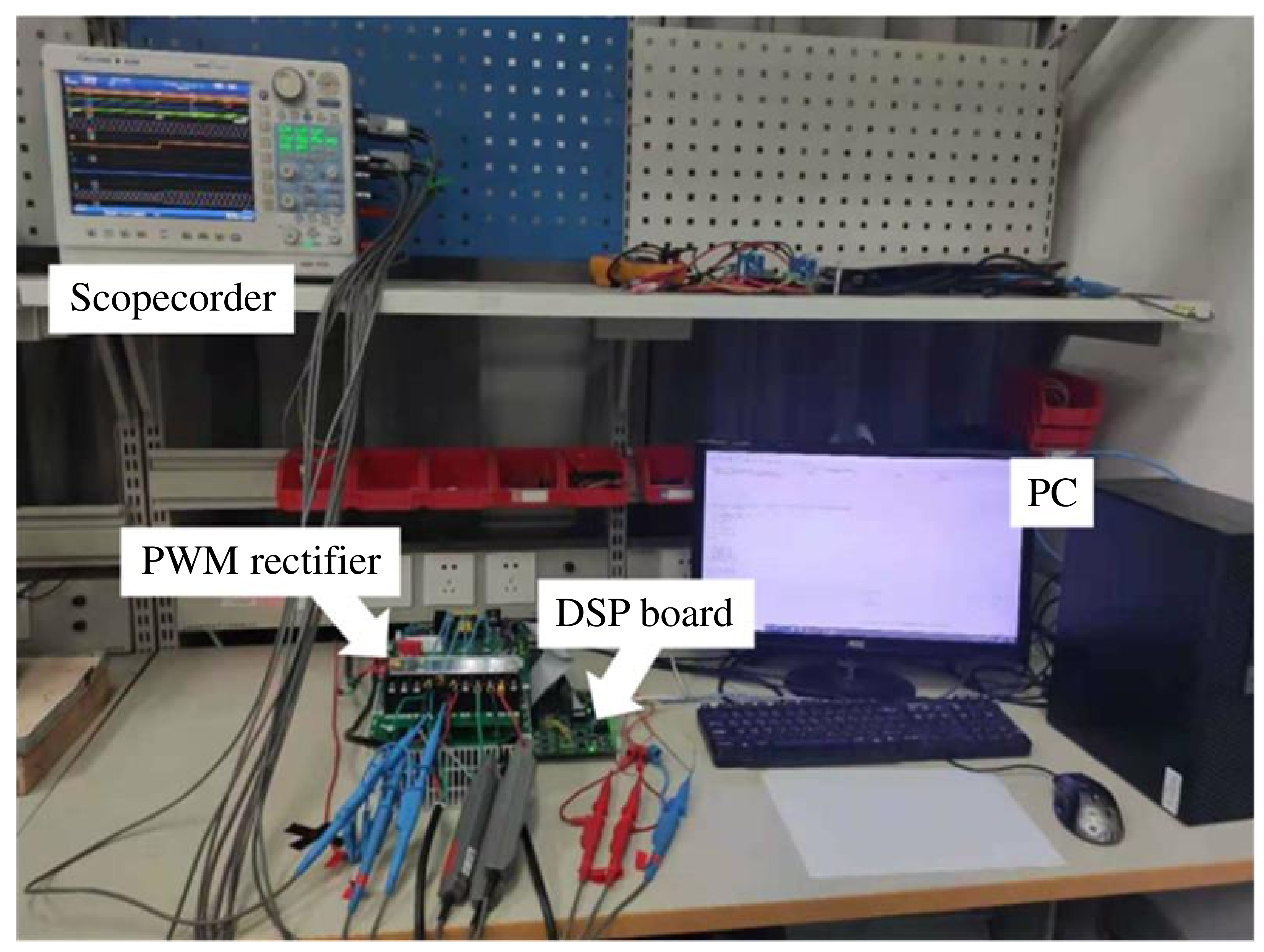
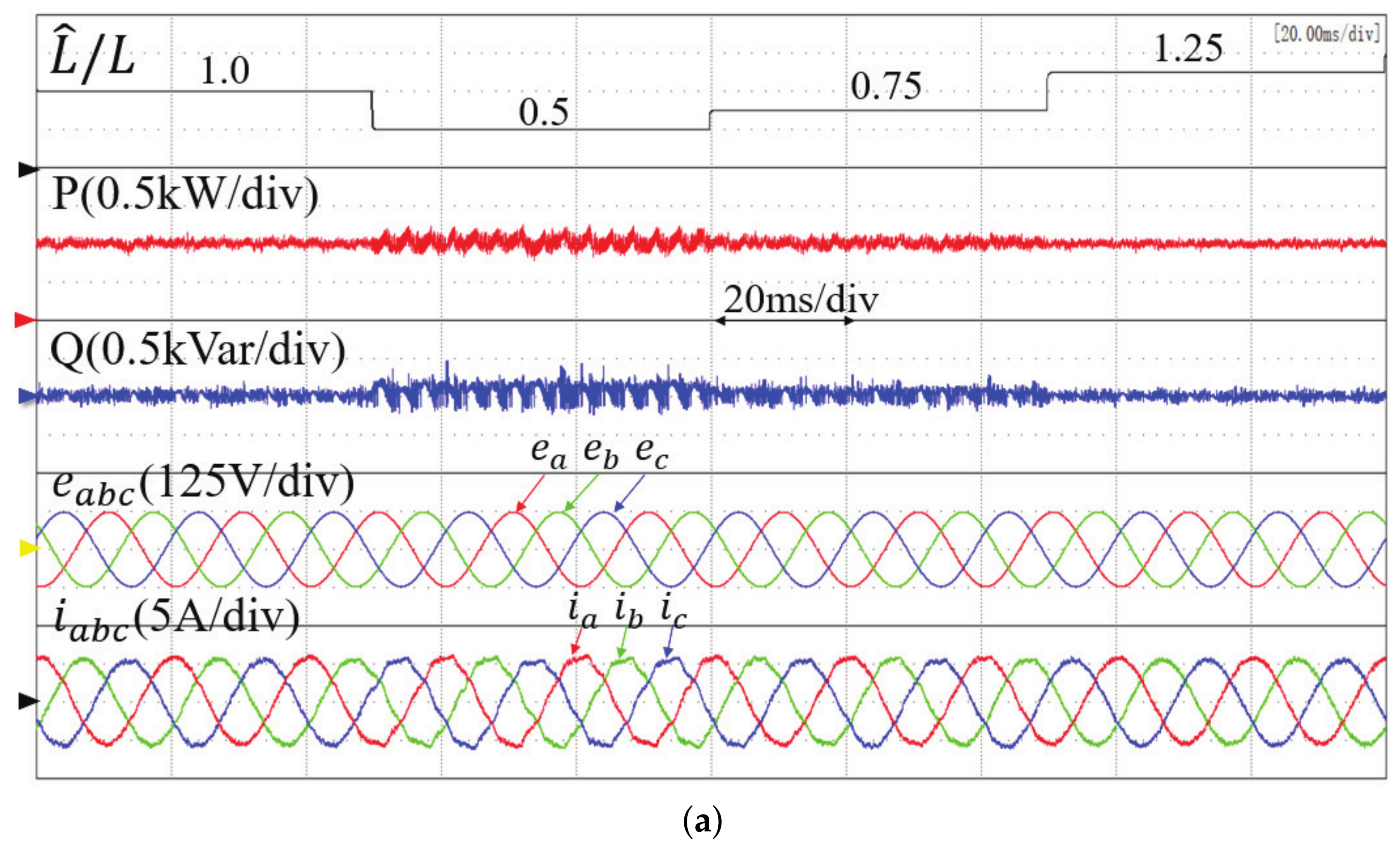
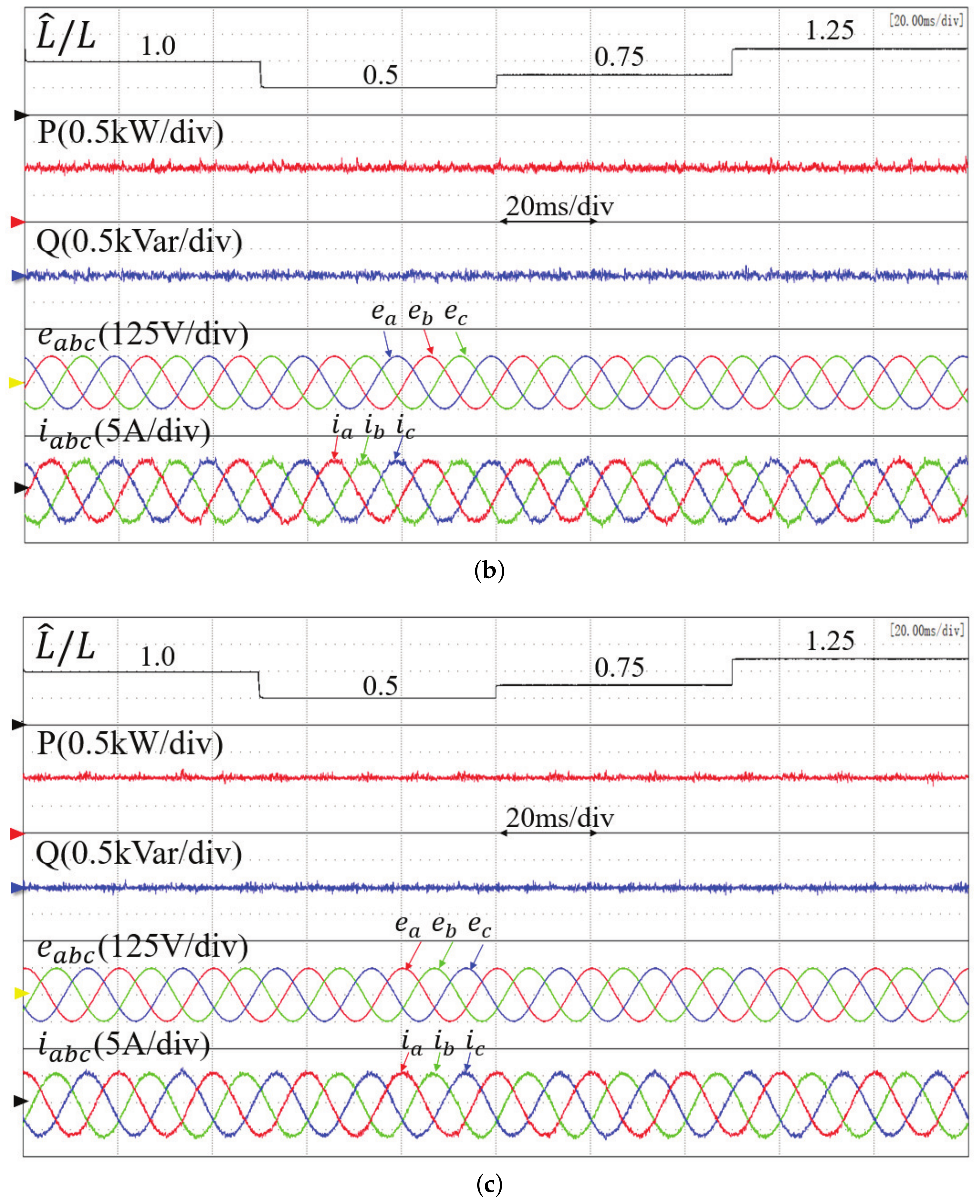
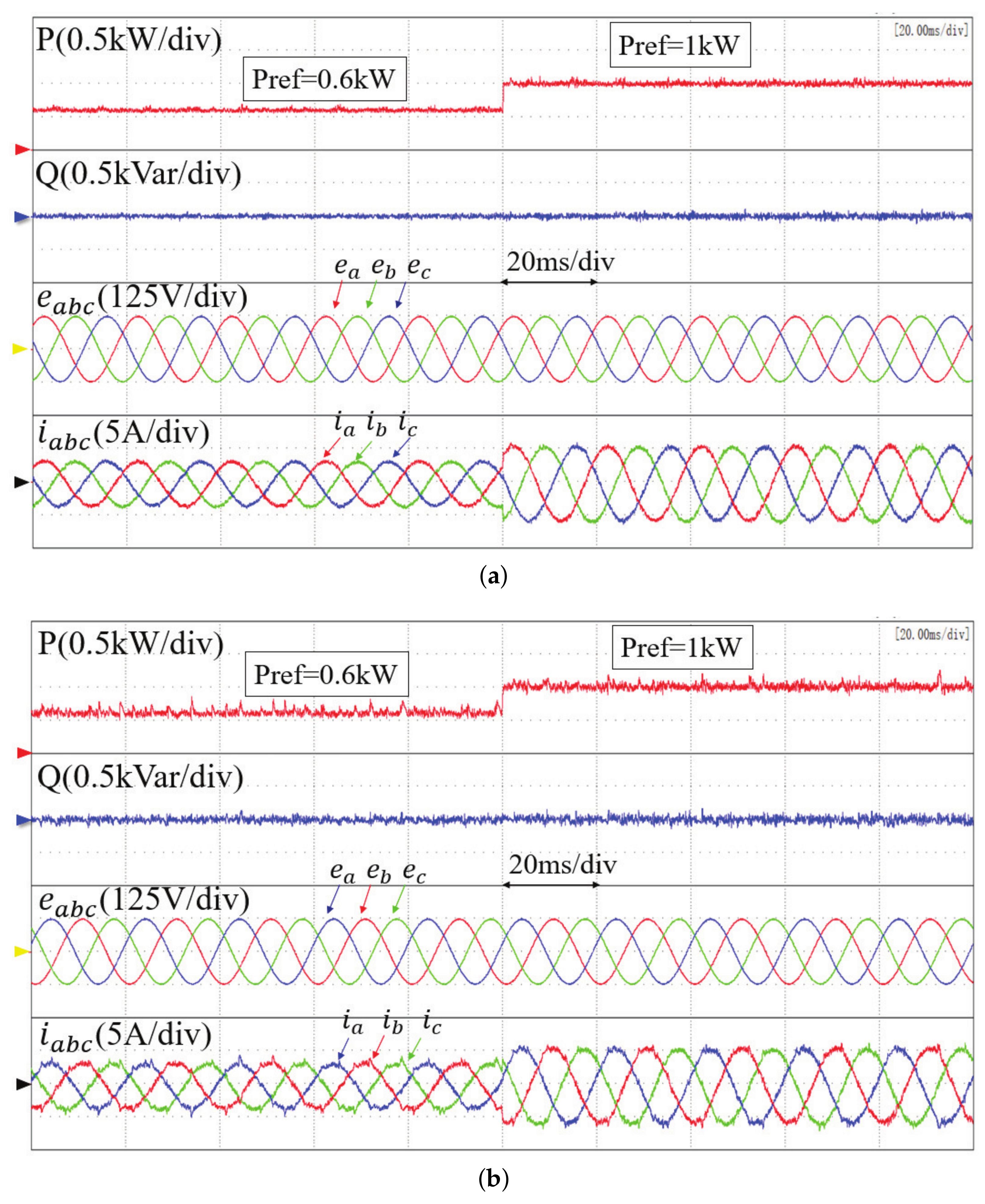
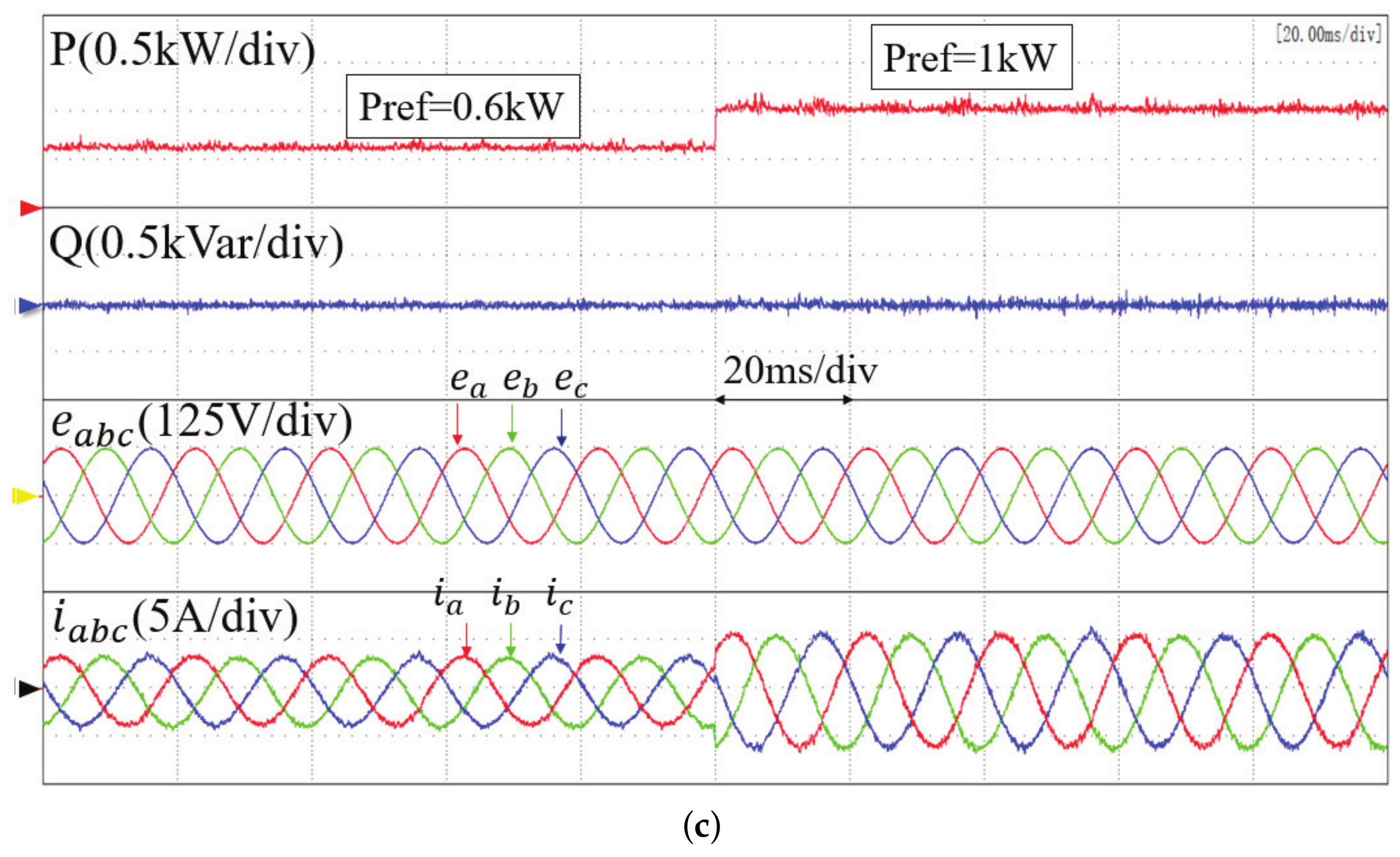
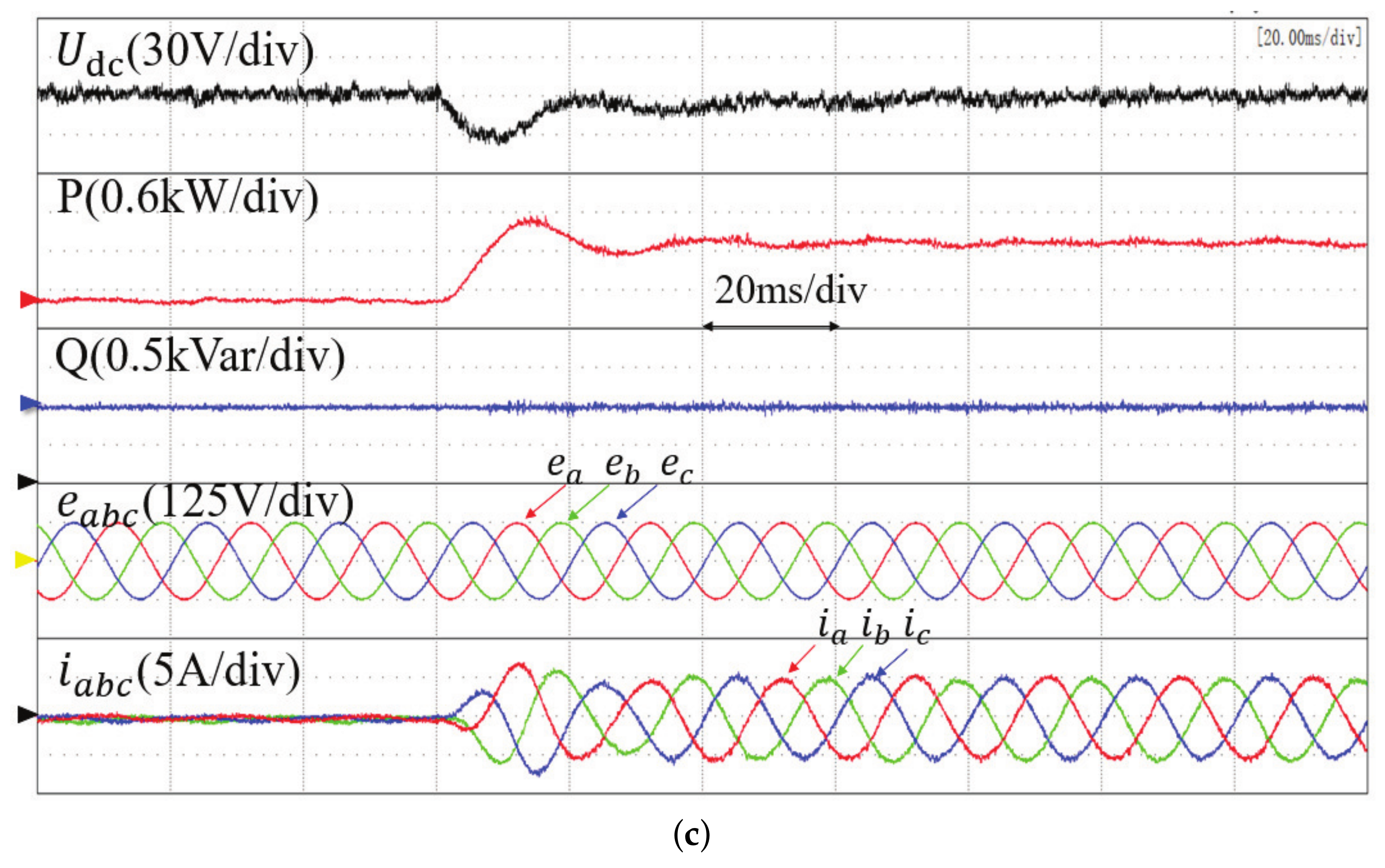
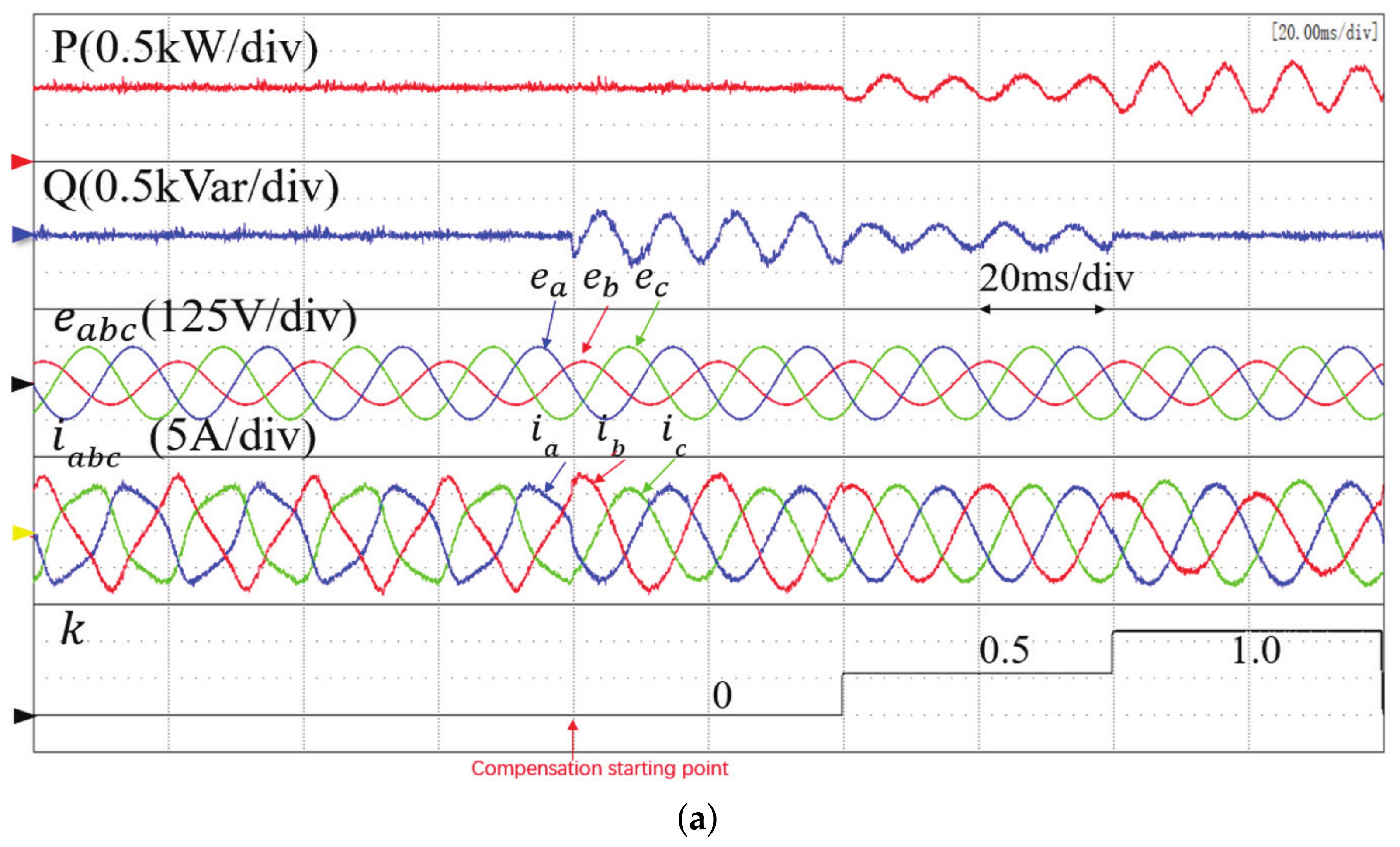
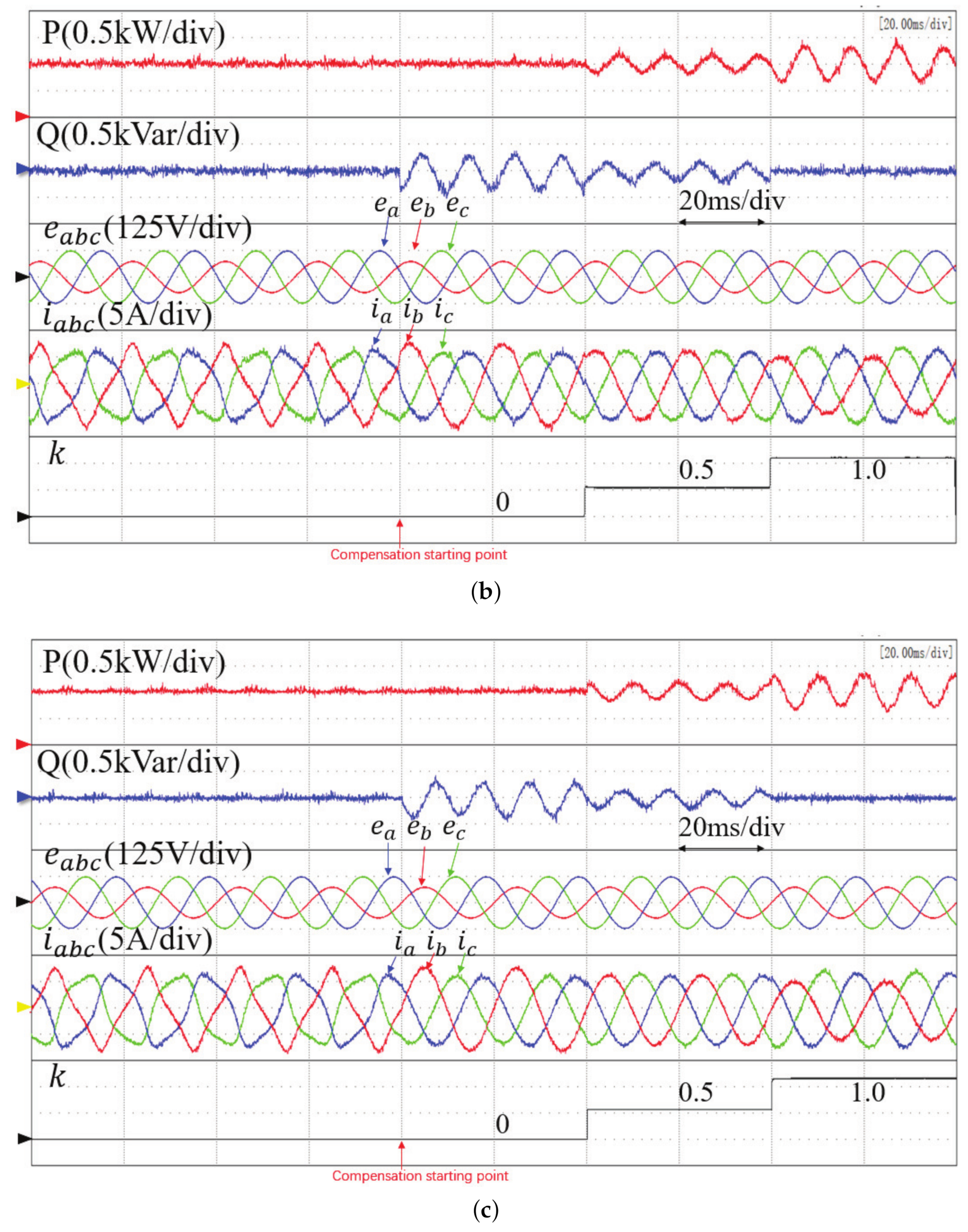
4. Experimental Results

In this section, the proposed two MFPPC methods are experimentally tested on a two-level platform shown in Figure 6. The experimental platform is composed of a three-phase two-level PWM rectifier, a digital signal processing (DSP) control board, a personal computer (PC), a scopecorder, a programmable AC source, three-phase filter inductance, and load resistance. For the aim of comparison, the results obtained from conventional model-based MPPC are also presented. The parameters of the PWM rectifier and control systems are listed in Table 3. To achieve the instantaneous power factor operation of the system, the reactive power reference value Q r e f was set to zero.
The experimental results of different control methods when the inductance changes are shown in Figure 7. The control performance of conventional MPPC, the proposed basic MFPPC, and the proposed improved MFPPC method were compared under four different values of the precise inductance parameter: L, 0.5 L, 0.75 L, and 1.25 L. The active power reference value was set to 1 kW. The conventional MPPC method produces large ripples in the active power and reactive power at 0.5 L and 0.75 L, and the grid current is distorted. In contrast, the proposed basic MFPPC method avoids the dependence on a precise system of parameters, the active power and reactive power remain constant, and the current is sinusoidal. The improved MFPPC method exhibits better steady-state performance than that of the proposed basic MFPPC method. Table 4 shows the THD of the grid current with inductance parameters of 0.5 L, 0.75 L, and 1.25 L. The THD of the grid current under the improved MFPPC method is smaller than the other two methods. This results verify that the best steady-state performance and strong parameter robustness are both achieved in the proposed MFPPC.
With an accurate inductance value and balanced network, the power factors of conventional MPPC, the proposed basic MPPC, and the proposed improved MPPC are 0.993, 0.995, and 0.998, respectively. However, the power factor of conventional MPPC deteriorates with mismatched inductance. For example, when the inductance value used in the controller is 50% of its actual value, the power factor of conventional MPPC is 0.984, while the power factors of other two methods are almost affected.
Figure 8 compares the dynamic responses of conventional MPPC, the proposed basic MFPPC, and the improved MFPPC method when the active power reference steps from 0.6 kW to 1 kW under symmetrical grid conditions. It is seen that, in each method, the active power can quickly track the reference power and the reactive power remains at zero to achieve the unity power factor. The total harmonic distortion (THD) of the grid current for the three control methods is shown in Table 5. When the parameters are accurate, the conventional MPPC method and improved MFPPC method have better steady-state performance than the proposed basic MFPPC method, and the best steady-state performance is achieved in the proposed improved MFPPC.
Figure 9 shows the experimental results of a sudden load change for the three methods, in which the DC voltage reference is 300 V and a 100 Ω resistive load is suddenly applied to the system. It is seen that the DC voltage recovers to the original reference value of 300 V after a small voltage drop. The active power rises rapidly to balance the load change, and the reactive power remains constant. The THD of the grid current under conventional MPPC, the proposed basic MFPPC, and the improved MFPPC method is 5.08%, 7.49%, and 4.46%, respectively. The proposed improved method has the best steady-state performance.
The results above were obtained under symmetrical and sinusoidal grid voltage conditions. Figure 10 presents the experimental results of the three methods under unsymmetrical grid conditions, where a one-phase dip of 40% was applied to the three-phase grid voltages. According to the different power compensation value, the three control targets were achieved with different values of compensation gain k. When k = 1 or 0, the currents must be unbalanced to achieve the target of constant active power or constant reactive power. To achieve sinusoidal and balanced grid currents ( k = 0.5 ), both the active power and reactive power must be oscillating at twice the grid frequency due to the interaction between the grid currents and the negative sequence grid voltages. It is seen that, before the power compensation, the grid currents are highly distorted. After the power compensation, the grid currents become sinusoidal. The steady-state performance of the proposed improved MFPPC is even better than that of conventional MPPC with the control targets I and II, as confirmed by the current THD comparison in Table 6. With control target III, the lowest current THD is achieved in conventional MPPC. The highest current THD is obtained in the proposed basic MFPPC. It should be noted that in Figure 10, the curve of U D C is not presented due to the limited channels in the oscilloscope. However, the average value of output voltage U D C is maintained at its reference value irrespective of a balanced or unbalanced network. The only difference is that the ripple of U D C is proportional to the ripple of active power, as shown in [7]. As the focus of Figure 10 is to present the results under an unbalanced network, U D C is replaced by the coefficient k in (24), which represents various targets under the unbalanced network. The results validate the effectiveness of the universal power compensation expression in (24).

5. Conclusions

This paper proposed an improved MFPPC method based on a fast-updated ultralocal model. In each control period, the gain of the input voltage and the uncertain term of the system in the ultralocal model are estimated and updated by using the grid voltages and currents in the past control periods. As a result, the stagnant update of power variation in the conventional method is eliminated and strong robustness against parameter variations is achieved, which is confirmed by the experimental results with mismatched parameters in the controller. In addition, by using the extended control set voltage vector, the power tracking error can be controlled more accurately than in the proposed basic MFPPC method. As the steady power ripples are related to the extended finite control set of voltage vectors, it is possible to use more voltage vectors to achieve better steady-state performance, but the control complexity is also increased, which is a trade-off between steady-state performance and control complexity. Under unsymmetrical grid voltages, the proposed method can achieve different control targets through the addition of different power compensations to the original power references. These control targets include sinusoidal and symmetrical grid currents, active power ripple cancellation, and reactive power cancellation. The effectiveness of the proposed method was confirmed by the experimental results.

Author Contributions

Conceptualization, Y.Z. and Z.W.; methodology, Z.M.; software, Z.M. and Q.Q.; validation, Z.M., Q.Q. and Z.W.; formal analysis, Z.W.; investigation, Y.Z.; resources, Y.Z.; data curation, Q.Q.; writing—original draft preparation, Z.W. and Q.Q.; writing—review and editing, Y.Z.; visualization, Z.M.; supervision, Y.Z.; project administration, Y.Z.; funding acquisition, Y.Z. All authors have read and agreed to the published version of the manuscript.

Funding

This research was funded by the National Natural Science Foundation of China under Grant 52077002, in part by the National Key R&D Program of China under Grant 2021YFB2400702, and in part by the Scientific Project of Offshore Wind and Smart Energy from China Huaneng Group Corporation under Grant HNKJ20-H88.

Institutional Review Board Statement

Not applicable.

Informed Consent Statement

Not applicable.

Data Availability Statement

Data sharing not applicable.

Conflicts of Interest

The authors declare no conflict of interest.

References

  1. Yan, S.; Yang, Y.; Hui, S.Y.; Blaabjerg, F. A Review on Direct Power Control of Pulsewidth Modulation Converters. IEEE Trans. Power Electron. 2021, 36, 11984–12007. [Google Scholar] [CrossRef]
  2. Blasko, V.; Kaura, V. A new mathematical model and control of a three-phase AC-DC voltage source converter. IEEE Trans. Power Electron. 1997, 12, 116–123. [Google Scholar] [CrossRef]
  3. Noguchi, T.; Tomiki, H.; Kondo, S.; Takahashi, I. Direct power control of PWM converter without power-source voltage sensors. IEEE Trans. Ind. Appl. 1998, 34, 473–479. [Google Scholar] [CrossRef]
  4. Zhang, Y.; Qu, C. Table-Based Direct Power Control for Three-Phase AC/DC Converters Under Unbalanced Grid Voltages. IEEE Trans. Power Electron. 2015, 30, 7090–7099. [Google Scholar] [CrossRef]
  5. Zhou, D.; Jiang, C.; Quan, Z.; Li, Y.R. Vector Shifted Model Predictive Power Control of Three-Level Neutral-Point-Clamped Rectifiers. IEEE Trans. Ind. Electron. 2020, 67, 7157–7166. [Google Scholar] [CrossRef]
  6. Zhang, Y.; Qu, C. Model Predictive Direct Power Control of PWM Rectifiers Under Unbalanced Network Conditions. IEEE Trans. Ind. Electron. 2015, 62, 4011–4022. [Google Scholar] [CrossRef]
  7. Zhang, Y.; Peng, Y.; Qu, C. Model Predictive Control and Direct Power Control for PWM Rectifiers With Active Power Ripple Minimization. IEEE Trans. Ind. Appl. 2016, 52, 4909–4918. [Google Scholar] [CrossRef]
  8. Chen, W.H.; Yang, J.; Guo, L.; Li, S. Disturbance-Observer-Based Control and Related Methods—An Overview. IEEE Trans. Ind. Electron. 2016, 63, 1083–1095. [Google Scholar] [CrossRef] [Green Version]
  9. Xia, C.; Wang, M.; Song, Z.; Liu, T. Robust Model Predictive Current Control of Three-Phase Voltage Source PWM Rectifier With Online Disturbance Observation. IEEE Trans. Ind. Informat. 2012, 8, 459–471. [Google Scholar] [CrossRef]
  10. Zhang, Y.; Liu, X.; Li, B.; Liu, J. Robust predictive current control of PWM rectifier under unbalanced and distorted network. IET Power Electron. 2021, 14, 797–806. [Google Scholar] [CrossRef]
  11. Wang, B.; Xu, Y.; Shen, Z.; Zou, J.; Li, C.; Liu, H. Current Control of Grid-Connected Inverter With LCL Filter Based on Extended-State Observer Estimations Using Single Sensor and Achieving Improved Robust Observation Dynamics. IEEE Trans. Ind. Electron. 2017, 64, 5428–5439. [Google Scholar] [CrossRef]
  12. Silva, J. Sliding-mode control of boost-type unity-power-factor PWM rectifiers. IEEE Trans. Ind. Electron. 1999, 46, 594–603. [Google Scholar] [CrossRef]
  13. Mehreganfar, M.; Saeedinia, M.H.; Davari, S.A.; Garcia, C.; Rodriguez, J. Sensorless Predictive Control of AFE Rectifier With Robust Adaptive Inductance Estimation. IEEE Trans. Ind. Inform. 2019, 15, 3420–3431. [Google Scholar] [CrossRef]
  14. Lin, C.K.; Liu, T.H.; Yu, J.t.; Fu, L.C.; Hsiao, C.F. Model-Free Predictive Current Control for Interior Permanent-Magnet Synchronous Motor Drives Based on Current Difference Detection Technique. IEEE Trans. Ind. Electron. 2014, 61, 667–681. [Google Scholar] [CrossRef]
  15. Lai, Y.S.; Lin, C.K.; Chuang, F.P.; Yu, J.T. Model-free predictive current control for three-phase AC/DC converters. IET Electr. Power Appl. 2017, 11, 729–739. [Google Scholar] [CrossRef]
  16. Carlet, P.G.; Tinazzi, F.; Bolognani, S.; Zigliotto, M. An Effective Model-Free Predictive Current Control for Synchronous Reluctance Motor Drives. IEEE Trans. Ind. Appl. 2019, 55, 3781–3790. [Google Scholar] [CrossRef] [Green Version]
  17. Le, V.T.; Lee, H.H. An Enhanced Model-Free Predictive Control to Eliminate Stagnant Current Variation Update for PWM Rectifiers. IEEE J. Emerg. Sel. Top. Power Electron. 2021, 9, 6804–6816. [Google Scholar] [CrossRef]
  18. Fliess, M.; Join, C. Model-free control. Int. J. Control 2013, 86, 2228–2252. [Google Scholar] [CrossRef] [Green Version]
  19. Zhang, Y.; Jin, J.; Huang, L. Model-Free Predictive Current Control of PMSM Drives Based on Extended State Observer Using Ultralocal Model. IEEE Trans. Ind. Electron. 2021, 68, 993–1003. [Google Scholar] [CrossRef]
  20. Rahoui, A.; Bechouche, A.; Seddiki, H.; Ould Abdeslam, D. Virtual Flux Estimation for Sensorless Predictive Control of PWM Rectifiers Under Unbalanced and Distorted Grid Conditions. IEEE J. Emerg. Sel. Top. Power Electron. 2021, 9, 1923–1937. [Google Scholar] [CrossRef]
  21. Song, H.S.; Nam, K. Dual current control scheme for PWM converter under unbalanced input voltage conditions. IEEE Trans. Ind. Electron. 1999, 46, 953–959. [Google Scholar] [CrossRef]
  22. Eloy-Garcia, J.; Arnaltes, S.; Rodriguez-Amenedo, J. Direct power control of voltage source inverters with unbalanced grid voltages. IET Power Electron. 2008, 1, 395–407. [Google Scholar] [CrossRef]
  23. Zhang, Y.; Jiao, J.; Xu, D.; Jiang, D.; Wang, Z.; Tong, C. Model Predictive Direct Power Control of Doubly Fed Induction Generators Under Balanced and Unbalanced Network Conditions. IEEE Trans. Ind. Appl. 2020, 56, 771–786. [Google Scholar] [CrossRef]
  24. Holtz, J. The representation of AC machine dynamics by complex signal flow graphs. IEEE Trans. Ind. Electron. 1995, 42, 263–271. [Google Scholar] [CrossRef] [Green Version]
  25. Akagi, H.; Kanazawa, Y.; Nabae, A. Instantaneous Reactive Power Compensators Comprising Switching Devices without Energy Storage Components. IEEE Trans. Ind. Appl. 1984, 20, 625–630. [Google Scholar] [CrossRef]
  26. Abad, G.; Rodriguez, M.A.; Iwanski, G.; Poza, J. Direct Power Control of Doubly-Fed-Induction-Generator-Based Wind Turbines Under Unbalanced Grid Voltage. IEEE Trans. Power Electron. 2010, 25, 442–452. [Google Scholar] [CrossRef]
  27. Liu, H.; Hu, H.; Chen, H.; Zhang, L.; Xing, Y. Fast and Flexible Selective Harmonic Extraction Methods Based on the Generalized Discrete Fourier Transform. IEEE Trans. Power Electron. 2018, 33, 3484–3496. [Google Scholar] [CrossRef]
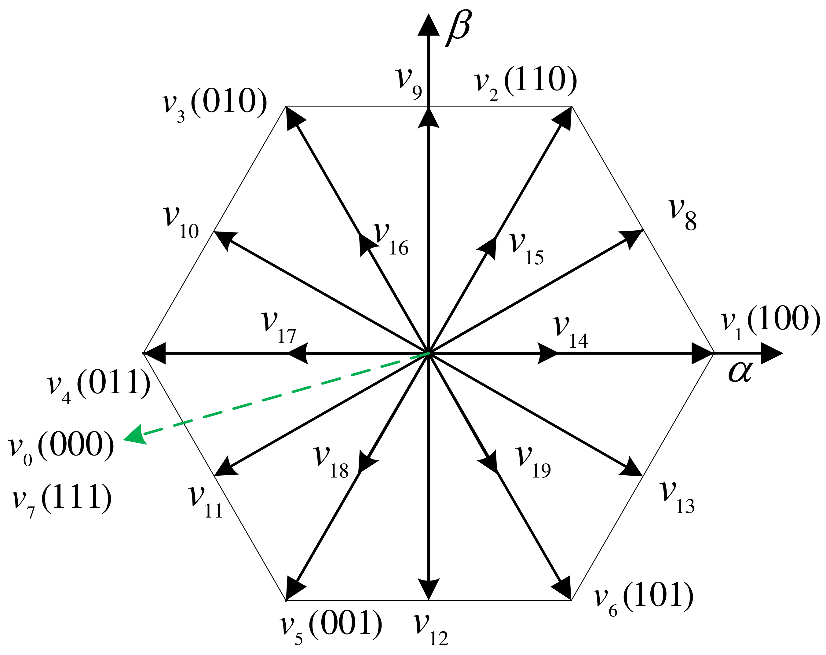
Figure 1. Topology of a two-level PWM rectifier.
Symmetry 14 01224 g001
Figure 2. Simulation results of (a) conventional MFPPC and (b) the proposed basic MFPPC.
Symmetry 14 01224 g002aSymmetry 14 01224 g002b
Figure 3. Basic schematic diagram of the proposed basic MFPPC method.
Symmetry 14 01224 g003
Figure 4. Extended finite control set of voltage vectors.
Symmetry 14 01224 g004
Figure 5. Control diagram of the proposed improved MFPPC method.
Symmetry 14 01224 g005
Figure 6. Experimental platform for the PWM rectifier system.
Symmetry 14 01224 g006
Figure 7. Experimental results of different control methods as the inductance changes. (a) Conventional MPPC. (b) Proposed basic MFPPC. (c) Proposed improved MFPPC.
Symmetry 14 01224 g007aSymmetry 14 01224 g007b
Figure 8. Experimental results of transient responses when P r e f increases from 0.6 kW to 1 kW. (a) Conventional MPPC, (b) proposed basic MFPPC, and (c) proposed improved MFPPC.
Symmetry 14 01224 g008aSymmetry 14 01224 g008b
Figure 9. Experimental dynamic response to a sudden load change. (a) Conventional MPPC. (b) Proposed basic MFPPC. (c) Proposed improved MFPPC.
Symmetry 14 01224 g009aSymmetry 14 01224 g009b
Figure 10. Steady-state experimental results of different control methods under unsymmetrical power grid conditions. (a) Conventional MPPC. (b) Proposed basic MFPPC. (c) Proposed improved MFPPC.
Symmetry 14 01224 g010aSymmetry 14 01224 g010b
Table 1. The 20 extended voltage vectors in the proposed MFPPC.
Vector No.Complex Vectors
v 1 2 3 U D C
v 2 2 3 U D C e j π 3
v 3 2 3 U D C e j 2 π 3
v 4 2 3 U D C
v 5 2 3 U D C e j 4 π 3
v 6 2 3 U D C e j 5 π 3
v 0 , 7 0
v 8 1 3 U D C e j π 6
v 9 j 3 U D C
v 10 1 3 U D C e j 5 π 6
v 11 1 3 U D C e j 7 π 6
v 12 j 3 U D C
v 13 1 3 U D C e j 11 π 6
v 14 1 3 U D C
v 15 1 3 U D C e j π 3
v 16 1 3 U D C e j 2 π 3
v 17 1 3 U D C
v 18 1 3 U D C e j 4 π 3
v 19 1 3 U D C e j 5 π 3
Table 2. Power compensation value under three control targets.
Control TargetPower Compensation Value
Target I S c o m p = e e + S r e f
Target II S c o m p = j 2 · Im e e + S r e f
Target III S c o m p = 2 · Re e e + S r e f
Table 3. System and Control Parameters.
System ParameterSymbolValue
Line resistance R f 0.3 Ω
Line inductance L f 10 mH
DC-side capacitanceC840 μ F
Load resistance R L 100 Ω
Line–line voltage U N 150 V
Line voltage frequencyf50 Hz
DC-side voltage U D C 300 V
Sampling frequency f s 20 kHz
Table 4. Current THD of three methods with inductance mismatches.
L ^ MethodTHD of i
0.5 LConventional MPPC6.51%
Proposed basic MFPPC6.82%
Proposed improved MFPPC3.89%
0.75 LConventional MPPC5.09%
Proposed basic MFPPC6.85%
Proposed improved MFPPC3.95%
1.25 LConventional MPPC5.34%
Proposed basic MFPPC6.91%
Proposed improved MFPPC4.02%
Table 5. Current THD of the three methods with different active power.
P ref MethodTHD of i
Conventional MPPC5.38%
600 WProposed basic MFPPC10.27%
Proposed improved MFPPC5.13%
Conventional MPPC4.17%
1000 WProposed basic MFPPC6.77%
Proposed improved MFPPC4.07%
Table 6. Current THD comparison of the three methods with unsymmetrical grid voltage conditions.
MethodTHD of i
k = 0 k = 0 . 5 k = 1
Conventional MPPC4.29%4.08%4.31%
Proposed basic
MFPPC
6.76%6.23%6.65%
Proposed improved
MFPPC
4.22%3.66%4.67%
Publisher’s Note: MDPI stays neutral with regard to jurisdictional claims in published maps and institutional affiliations.

