Article

Asymmetric Orientation Combination for Reversible and Authenticable Data Hiding of Dual Stego-images

1
School of Computer and Information Engineering, Xiamen University of Technology, Xiamen 361024, China
2
Department of Information Engineering and Computer Science, Feng Chia University, Taichung 40724, Taiwan
3
Department of Electronic Engineering, National Quemoy University, Kinmen 89250, Taiwan
4
AI Research Center, Hon Hai (Foxconn) Research Institute, Taipei City 114699, Taiwan
*
Authors to whom correspondence should be addressed.
Symmetry 2022, 14(4), 819; https://doi.org/10.3390/sym14040819
Submission received: 22 March 2022 / Revised: 7 April 2022 / Accepted: 12 April 2022 / Published: 14 April 2022
(This article belongs to the Special Issue Symmetric and Asymmetric Encryption in Blockchain)

Abstract

:
A dual-image-based reversible data hiding (RDH) scheme can conceal secret data into a cover image by creating two steganographic images. These two stego-images can cooperate to extract secret data and restore the cover image. This paper describes a generalization of the orientation combination technology for dual-image-based RDH. We first propose a full search algorithm to find the optimal set of the reversible orientation combinations. Based on the algorithm, the modification range of pixel values can be dynamically enlarged, and thus the embedding capacity becomes adjustable. In addition, an authentication algorithm is provided to detect tampered shadows based on a faithful one. Experimental results confirm that the proposed scheme can produce dual stego-images with a good visual quality. Furthermore, our method provides an adjustable payload. A lot more secret data can be embedded than with state-of-the-art methods, with a satisfactory image quality. Two steganalysis tools are applied to demonstrate the security level of the proposed scheme.

1. Introduction

Data-hiding technology plays an important role in the protection of copyright and privacy in image storage and transmission. However, conventional data hiding techniques [1,2,3,4,5] suffer from image distortion after data embedding, which is unacceptable in some critical scenarios such as military, medical, and legal copyright. Reversible data hiding (RDH), which can recover the original image accurately after the embedded secret data are extracted, is more applicable for these scenarios.
According to the embedding technique, RDH schemes can be roughly categorized into two types: the difference expansion (DE) [6,7] and the histogram shifting (HS) [8,9,10,11]. The DE-based RDH method was first introduced by Tian [6]. In his method, the secret data were embedded into the difference of each pixel pair. Although a maximum embedding capacity (EC) of 0.5 bits per pixel (bpp) can be achieved, it requires auxiliary data to restore the cover image. In 2006, Ni et al. [8] proposed an HS-based algorithm for RDH. They first calculated the relative frequency of each pixel value and drew the histogram. Then, the secret data were embedded into the peak bin of the histogram. Since the pixel value in the cover image was shifted by one at most, the visual quality of the stego-images is very good. However, the embedding capacity is low since the peak bin of the histogram contains just a small portion of the image pixels.
More topics on data-hiding techniques have been studied in recent years. Instead of hiding binary secret data, Alfa et al. [12] proposed a method to hide large audio files in smaller image carriers. Hiding audio file in digital media is a different challenge in image steganography. In 2021, Geetha et al. [13] proposed a Fourier domain technique to disrupt the stego content in carrier images. Without losing the visual quality of the carrier image, a major portion of the embedded data can be removed.
Unlike the traditional RDH methods, which generate a single stego-image after data embedding, the secret sharing scheme proposed by Naor and Shamir [14] hides the secret data into multiple stego-images. Their method creates n stego-images after embedding the secret data and distributes these stego-images to n participants. The secret data can be recovered when k or more stego-images are gathered. However, there are two main problems with their method. First, the generated stego-images are meaningless, which may catch the attention of malicious persons. Secondly, their method suffers from scale expansion of stego-images. To overcome these drawbacks, various secret sharing schemes have been proposed [15,16,17,18]. Fang [16] proposed a method that can recover the embedded secret image directly by stacking two shadows, thereby avoiding the scale-expansion problem. In 2020, Harn et al. [18] proposed a scheme that can generate meaningful shadows. Any k of n shadows can cooperate to retrieve the embedded secret binary image without additional arithmetic computation.
Dual-image-based RDH schemes [19,20,21] can be regarded as a special case of ( k , n ) -threshold secret sharing with k = n = 2 . The concept of a dual-image-based RDH scheme was first introduced by Chang et al. [19] in 2007. In their method, two five-base digits were embedded into a pixel pair of the cover image along the main-diagonal and the anti-diagonal directions of the exploiting modification direction (EMD) matrix, and the EC of this scheme is 1 bpp. To improve the visual quality of the stego-image, Chang et al. [20] used the horizontal and the vertical directions of EMD matrix instead of the main-diagonal and anti-diagonal directions to embed the two five-base digits. Thus, the peak signal-to-noise ratio (PSNR) rose to 48 dB. In 2021, Chen et al. [21] introduced a novel dual-image-based RDH scheme with the assistance of EMD reference matrix. Each cover pixel was duplicated into a pixel pair and embedded with 1 + log 2 5 secret bits along its horizontal or vertical directions, using a generated random binary stream. Although the PSNR of the generated shadows is less than 42 dB, its EC is raised to 1.56 bpp.
Dual-image-based RDH schemes that use the orientation combination technique have been extensively explored [22,23]. In 2013, Lee and Huang [22] developed a novel RDH scheme based on dual stego-images. In their method, the secret bits were first converted into a sequence of five-base digits to enhance EC. Then, each cover pixel pair was used to conceal two five-base digits. The reversibility of their method is fulfilled by the orientation combination of the two stego pixel pairs. Since the original pixel value is only modified by at most plus or minus one, the PSNR value of the stego-images is about 49 dB. In 2020, Chen and Guo [23] introduced an RDH scheme based on fully exploiting the orientation combinations of dual stego-images. They bounded the values of the two generated stego pixel pairs within a 3 × 3 block centered at the position located by the cover pixel pair. Then, the whole orientation combinations were labeled from 0 to 24, so that each orientation combination could be exploited to embed a 25-base secret digit. The EC of their scheme rose to 1.14 bpp with a good PSNR value of 49.92 dB. However, the generalizability of this method in terms of block size expansion has yet to improve.
The authentication capability of a tampered shadow to be detected by a faithful shadow is another concern of the secret sharing approaches [24,25,26,27,28]. In 2007, Yang et al. [24] proposed a secret sharing scheme with authentication. However, the authentication ability and the visual quality of stego-images are not satisfactory. Later, a novel (2, 2)-threshold secret sharing scheme based on the turtle shell (TS) matrix was proposed by Liu et al. [25] in 2018. In their method, a good visual quality can be guaranteed since the modification of the cover pixel value is no more than two. In addition, an authentication mechanism with a cheating detection rate of 95% is given. In 2019, Lin et al. [26] proposed a novel (2, 2)-threshold secret sharing scheme using the EMD matrix. In the comparison of the methods proposed in [25,26], their EC and cheating detection rate are about the same. However, the performance of [26] is much better than that of [25] in terms of the visual quality of stego-images. In 2020, Gao et al. [27] proposed a (2, 3)-threshold secret sharing scheme with an authentication mechanism, which can detect 90% of tampered pixels. The next year, Lin et al. [28] proposed a crystal lattice matrix for the same secret sharing scheme. Based on the new matrix, the detection rate of tampered pixels is increased to 99%. In spite of the high authentication ability, the pixel-value distortion due to data embedding can be further reduced.
Inspired by the orientation combination techniques [23], we propose a full search algorithm to search for the optimal set of orientation combinations in a predefined modification block size. By setting different block sizes, this RDH scheme can be generalized to embed various numbers of secret data. In addition, we provide an authentication mechanism to detect the tampered shadows based on a faithful one. The novelty and main contributions of our method are listed below.
  • A full search algorithm is provided to find the optimal set of reversible orientation combinations for different block sizes;
  • Based on the orientation combinations of various block sizes, an RDH scheme for dual stego-images with adjustable amount of payloads is proposed;
  • An authentication method is designed to detect tampered stego-images using a faithful one.
The rest of this paper is organized as follows. Section 2 describes the method proposed by Chen and Guo [23]. Section 3 introduces the proposed full-search algorithm, the generalized RDH scheme, and the authentication mechanism. In Section 4, experiments are conducted to evaluate the performance of the proposed scheme. A comparison with related works is also presented. Conclusions are given in Section 5.

2. Review of Gao et al.’s Method

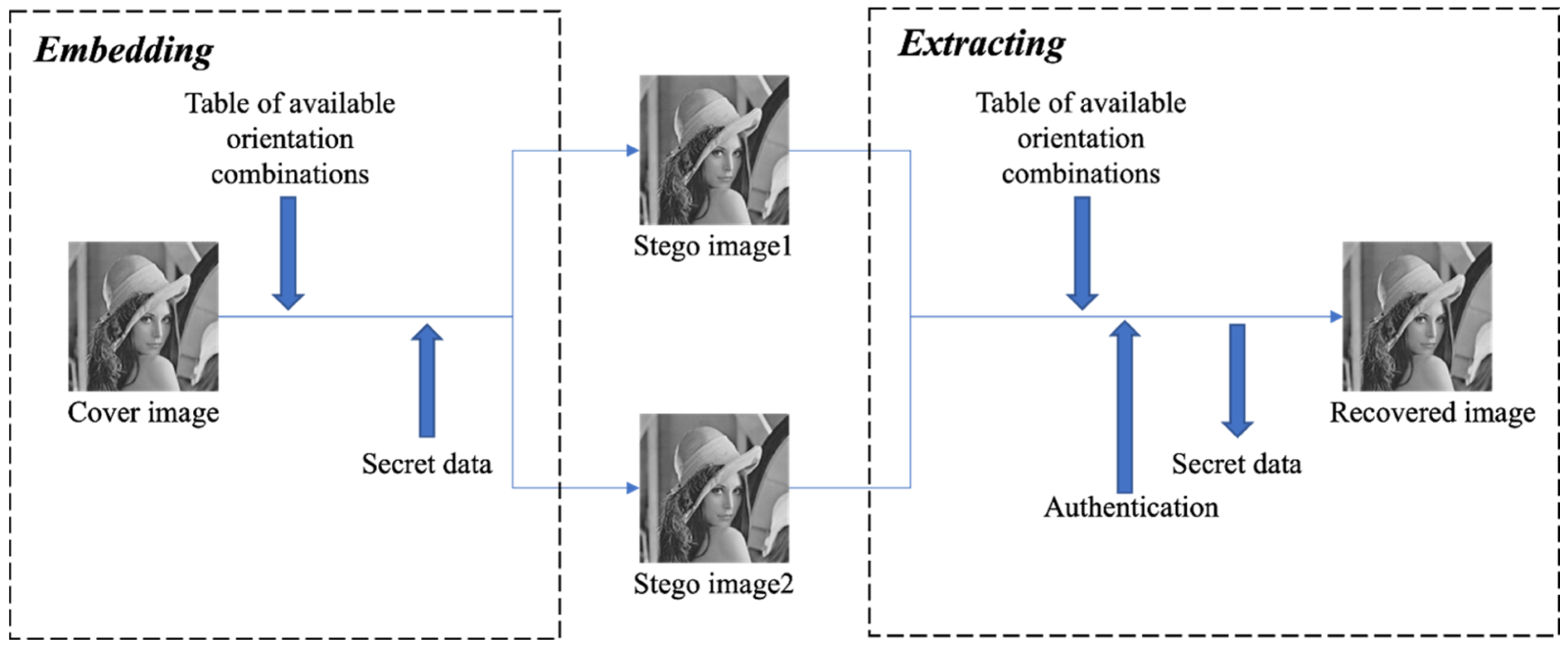
We give a brief introduction to the method proposed by Chen and Guo [23], which is the basis of our work. Their method consists of three phases: (1) generation of the rule table, (2) the data embedding, and (3) the data extraction and image recovery.

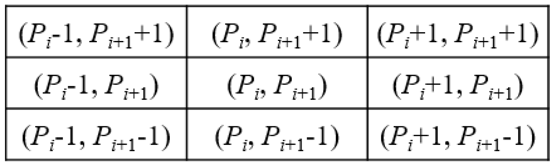
2.1. Rule Table Generation

In Chen and Guo’s method, two consecutive cover pixels (Pi, Pi+1) are treated as a unit and mapped into a two-dimensional space in which Pi was considered as the abscissa and Pi+1 as the ordinate. Two stego-pixel pairs are generated from (Pi, Pi+1) by embedding a secret digit, v, of which is one referred to as the major one and is denoted as (Mi, Mi+1) and the other is referred to as the auxiliary one and is denoted as (Ai, Ai+1). Note that these two stego-pixel pairs are restricted within a 3 × 3 block centered at (Pi, Pi+1), as shown in 
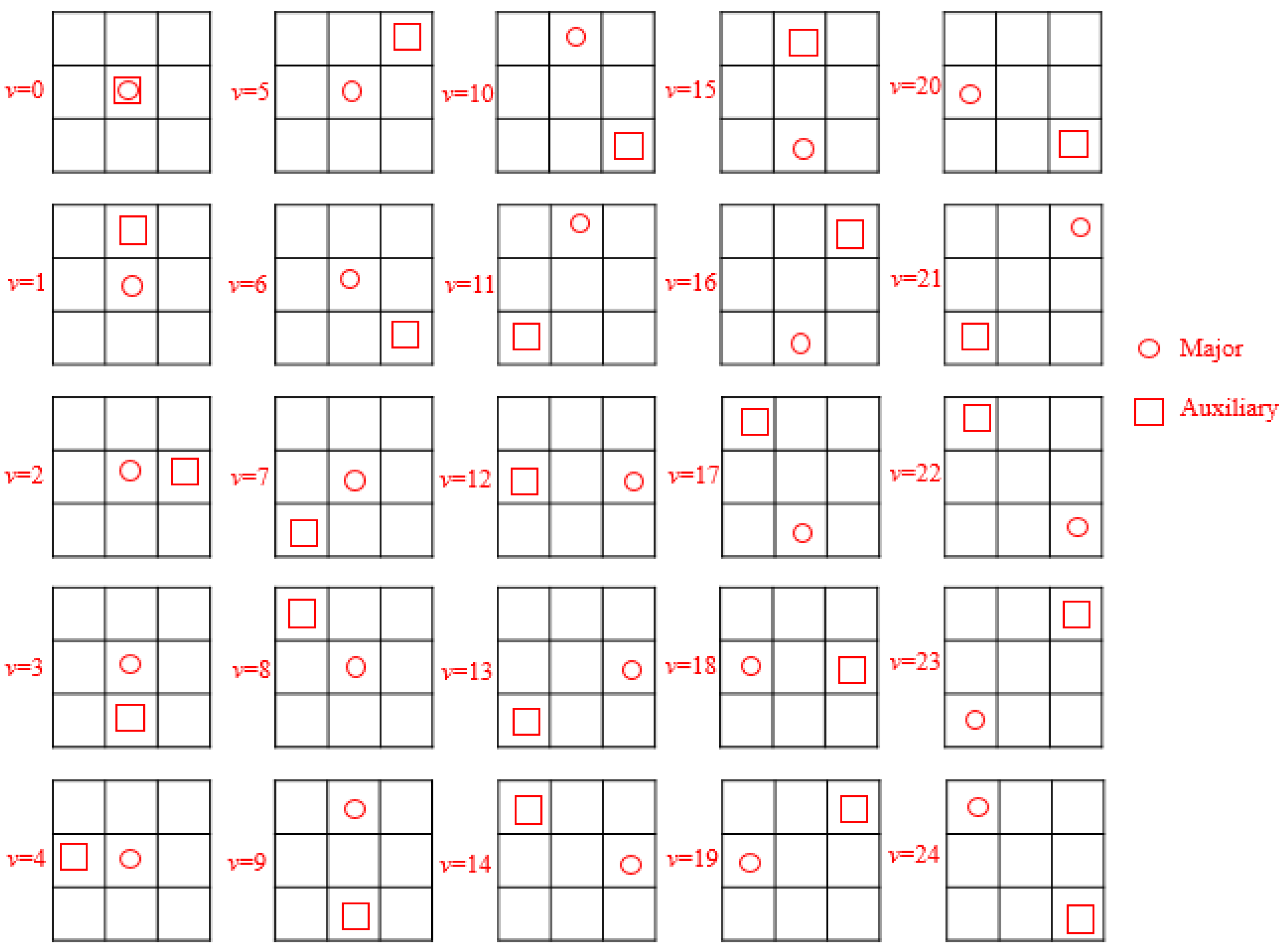
Figure 1. Each orientation combination of (Mi, Mi+1) and (Ai, Ai+1) in the 3 × 3 block can be represented as embedded secret digit, v, and can uniquely determine the cover unit (Pi, Pi+1). In their method, there are 25 orientation combinations of (Mi, Mi+1) and (Ai, Ai+1) in total, as shown in Figure 2. Furthermore, the embedding and extracting rules corresponding to these 25 orientation combinations are shown in Table 1. The column of (di, di+1) in Table 1 denotes the difference between two stego-pixel pairs calculated by
( d i , d i + 1 ) = ( M i A i , M i + 1 A i + 1 ) .

2.2. Data Embedding

Given a cover image I-sized W × H, Chen and Guo’s scheme [23] first rearranges it into a sequence of pixel pairs S = { ( P i , P i + 1 ) , i = 1 , 3 , , W × H 1 } in a raster scan order. Each cover pixel pair ( P i , P i + 1 ) is used to embed a 25-base secret digit v and generate ( M i , M i + 1 ) and ( A i , A i + 1 ) through the guidance of Table 1. The embedding rule is given in Equation (2), where the subscripts M v and A v indicate retrieving the major and auxiliary pixel pairs by substituting ( P i , P i + 1 ) into the corresponding entries at the row number v of Table 1. The dual pixel pairs are then be assigned to the dual stego-images S1 and S2, respectively. The dual stego-images can be produced after processing the whole sequence in the same way.
{ ( M i , M i + 1 ) = ( P i , P i + 1 ) M v ( A i , A i + 1 ) = ( P i , P i + 1 ) A v .
Now we use a simple example to demonstrate the embedding procedure. Suppose that two 25-base secret digits V = {24, 4}25 are to be embedded into two cover pixel pairs S = {(5, 6), (8, 8)}. The procedures are as follows.
(i) Select a cover pixel pair (5, 6) from S and a 25-base secret digit {24}25 from V. According to the rules in Table 1, two stego pixel pairs are calculated by ( M i , M i + 1 ) = ( 5 ,   6 ) M 24 = ( P i 1 , P i + 1 + 1 ) = ( 5 1 , 6 + 1 ) = ( 4 , 7 ) and ( A i , A i + 1 ) = ( 5 ,   6 ) A 24 = ( P i + 1 , P i + 1 1 ) = ( 5 + 1 , 6 1 ) = ( 6 ,   5 ) . Thus, the first shadow S1 comes out as {(4, 7)}, while the second shadow S2 comes out as {(6, 5)}.
(ii) Following the same procedure, two stego pixel pairs are calculated by ( M i , M i + 1 ) = ( 8 ,   8 ) M 4 = ( P i , P i + 1 ) = ( 8 , 8 ) and ( A i , A i + 1 ) = ( 8 ,   8 ) A 4 = ( P i 1 , P i + 1 ) = ( 8 1 , 8 ) = ( 7 , 8 ) when we embed {4}25 into the pixel pair (8, 8). Finally, the first shadow S1 turns out to be {(4, 7), (8, 8)}, while the second shadow S2 turns out to be {(6, 5), (7, 8)}.

2.3. Data Extraction and Image Recovery

Through the incorporation of the dual stego-images, the receiver can extract the embedded secret data and restore the cover image without loss. Sequentially select pixel pairs (Mi, Mi+1) from S1 and (Ai, Ai+1) from S2 in the corresponding location, the embedded secret digits and the original cover pixel pairs can be retrieved as follows.
Calculate (di, di+1) by Equation (1) and identify the row where (di, di+1) is located in Table 1 to extract the embedded 25-base secret digit v. Meanwhile, the cover pixel pair (Pi, Pi+1) can also be restored based on the value of v using Equation (3), where the subscript v indicates retrieving the cover pixel pair by substituting ( M i , M i + 1 ) into the last entry at the row number v of Table 1. After all pixel pairs of the dual stego-images have been processed, the complete secret data and the original cover image can be restored.
( P i , P i + 1 ) = ( M i , M i + 1 ) v .                  
An example of data extraction and pixel value recovery is illustrated by using the dual stego-images S1 = {(4, 7), (8, 8)} and S2 = {(6, 5), (7, 8)}. The detailed procedures are as follows.
(i)
Pick up two stego-pixel pairs (4, 7) and (6, 5) from S1 and S2, respectively. The difference of the two stego-pixel pairs can be calculated by Equation (1), i.e., (di, di+1) = (4 − 6, 7 − 5) = (−2, 2). Search (di, di+1) in Table 1, which we can find in the 24th row, which means the embedded digit is {24}25. Meanwhile, the cover pixel pair can be recovered by ( P i , P i + 1 ) = ( 4 ,   7 ) 24 = ( M i + 1 , M i + 1 1 ) = ( 4 + 1 , 7 1 ) = ( 5 , 6 ) . Thus, V comes out as {24}25 and S comes out as {(5, 6)}.
(ii)
Take the next stego-pixel pairs (8, 8) and (7, 8) into account. Calculate the (di, di+1) by Equation (1), i.e., (di, di+1) = (8 − 7, 8 − 8) = (1, 0). Then, the value of v can be determined as 4 according to Table 1. Thus, the embedded {4}25 is retrieved, and the cover pixel pair can be recovered by ( P i , P i + 1 ) = ( 8 ,   8 ) 4 = ( M i , M i + 1 ) = ( 8 , 8 ) . Finally, V comes out as {24, 4}25 and S comes out as {(5, 6), (8, 8)}.
For boundary-valued pixels, i.e., Pi   { 0 , 255 } or Pi+1   { 0 , 255 } , they are not used for data embedding but remain unchanged in two stego-pixel pairs. On the receiver side, if the corresponding pixels in two stego-pixel pairs are equal and belong to the boundary pixels, then it can tell that not secret data is embedded and both stego-pixel are exact cover pixels. Though the embedded secret digits and the cover image can be retrieved correctly, there are two drawbacks to Chen and Guo’s method.
(1)
It lacks an essential proof that there are at most 25 orient combinations of two stego-pixel pairs in a 3 × 3 block in their method.
(2)
It has some difficulties in extending the block size into 5 × 5, 7 × 7, or more.
In this paper, we solve the two drawbacks and propose a generalized orientation combination technique for a dual-image-based reversible and authenticable data-hiding scheme.

3. Generalized Orientation Combination and Proposed Scheme

The number of available orientation combinations in an r × r block is analyzed in Section 3.1. Section 3.2 describes the details of the proposed full search algorithm for available orientation combinations in an r × r block. Based on the generalized orientation combination, our dual-image-based RDH scheme with the authentication mechanism is elaborated in Section 3.3.

3.1. Available Asymmetric Patterns in r × r Block

Consider the orientation combinations of two stego-pixel pairs in a 3 × 3 block first. Theoretically, there are 81 orientation combinations in total, since there are nine candidate locations for each stego-pixel pair. Only 25 orientation combinations are available for data hiding, since there are ambiguities in the restoration process. For example, there are nine symmetric patterns, as shown in Figure 3, which are indistinguishable during restoration. To solve the ambiguities, only one pattern in the symmetric set of orientation combinations can be applied to embed secret data. In addition, we calculate the sum of square errors to find the best pattern, which causes minimum distortion after data embedding. The sum of square errors Q for the cover pixel pair (Pi, Pi+1) is defined by
Q ( M i , M i + 1 , A i , A i + 1 ) = ( M i P i ) 2 + ( M i + 1 P i + 1 ) 2 + ( A i P i ) 2 + ( A i + 1 P i + 1 ) 2 .
The number of available asymmetric patterns for two stego-pixel pairs in an r × r block ensures that reversibility can be defined.
Definition 1. 
The number of available orientation combinations for two stego-pixel pairs within an r × r block, where r is an odd integer, is given by
N = ( 2 × r 1 ) 2 .
Proof. 
(1) Given a cover pixel pair (Pi, Pi+1), we first calculate the deviation range [−t: t] of a cover pixel value by
t = ( r 1 ) / 2 .
The values of the dual stego-pixel pairs are within the range ( P i t : P i + t , P i + 1 t : P i + 1 + t ) .
(2) The difference vector between two stego-pixel pairs (di, di+1) is within the [−2t: 2t] range. Thus, the candidate value for di or di+1 equals to 4 × t + 1 = 2 × r − 1. Recall that only one of the translation-invariant combinations can be applied. That means only one pattern can be collected in the mapping table for each distinct difference vector. As a result, the number of available asymmetric patterns for the dual stego-pixel pairs is (2 × r − 1)2. Take the 3 × 3 block as an example; the number of orientation combinations for the dual stego-pixel pairs is (2 × 3 − 1)2 = 25, which is exactly the same as the table provided by Chen and Guo’s scheme [23]. □

3.2. Full Search Algorithm

We propose a full search algorithm to determine the optimal available orientation combinations for two stego-pixel pairs in an r × r block. In the algorithm, we first traverse the orientation combinations of two stego-pixel pairs in a predefined order and calculate (di, di+1) of each orientation combination. Then, all orientation combinations are grouped according to the value of (di, di+1). If there are multiple orientation combinations with the same (di, di+1), the orientation combination with the smallest Q is collected to the mapping table. More details are elaborated in Algorithm 1.
Algorithm 1: The full search algorithm for orientation combinations
Input: Block size r.
Output: Table list of the available orientation combinations Y.
1.
t = ( r 1 ) / 2
2.
List a table Y containing all possible values of the difference vector (di, di+1).
3.
Set initial values of (Mi, Mi+1), (Ai, Ai+1) in all rows to (Pi + t + 1, Pi+1 + t + 1).
4.
for M i = Pit to Pi + t {
5.
  for M i + 1 = Pi+1t to Pi+1 + t {
6.
    for A i = Pit to Pi + t {
7.
      for A i + 1 = Pi+1t to Pi+1 + t {
8.
        Calculate (di, di+1) according to Equation (1).
9.
        Retrieve (Mi, Mi+1) and (Ai, Ai+1) corresponding to (di, di+1) from Y.
10.
       Calculate Q ( M i , M i + 1 , A i , A i + 1 ) and Q ( M i , M i + 1 , A i , A i + 1 ) according to Equation (4).
11.
       If Q ( M i , M i + 1 , A i , A i + 1 ) < Q ( M i , M i + 1 , A i , A i + 1 ) {
12.
          Replace {(Mi, Mi+1), (Ai, Ai+1)} with { ( M i , M i + 1 ) , ( A i , A i + 1 ) } in Y.
13.
        }
14.
      }
15.
    }
16.
  }
17.
}
18.
Return Y.
Table 2 lists the result table of orientation combinations for a 3 × 3 sized block. There are 25 combinations, which matches the table provided by Chen and Guo’s scheme [23]. Although the generated major stego pixel pair (Mi, Mi+1) and the auxiliary one (Ai, Ai+1) for the same value of (di, di+1) in our result may be different from those in Table 1, their distortion values are identical. As a result, the image quality of the dual stego-images is theoretically identical to each other after applying Table 1 or Table 2 for data embedding.
Table 3 lists the resulting table of orientation combinations for a 5 × 5-sized block. There are 81 orientation combinations in total according to Equation (5). Since the first 25 values of v are identical to those in Table 2, Table 3 lists the remaining part of the table. The column of (Pi, Pi+1) is omitted in Table 3 since they can be easily derived from (Mi, Mi+1).
According to Equation (5), the numbers of useful orientation combinations for the 7 × 7 block and 9 × 9 blocks are 169 and 289, respectively. The list of available orientation combinations can also be obtained by Algorithm 1.

3.3. Proposed Scheme and Authentication Mechanism

In real applications, the block size r can be adjusted by adapting to the required payload. Once the block size r is determined, the number of useful orientation combinations, N, in an r × r block can be calculated according to Equation (5) and the list of available orientation combinations can be obtained by applying Algorithm 1. Based on the generalized orientation combination, we propose an RDH scheme with an authentication mechanism in dual stego-images. The flowchart of our proposed scheme is shown in Figure 4.
Similar to Chen and Guo’s scheme [23], we also rearrange the cover image I into a sequence of pixel pairs. Each pair is used to conceal an N-based secret digit, and two stego-pixel pairs are produced and assigned to the dual stego-images. The embedding and the extracting procedures are all identical to Chen and Guo’s scheme.
Recall that two generated stego-pixel pairs, (Mi, Mi+1) and (Ai, Ai+1), are within the r × r block centered with the cover pixel pair. According to Section 3.1, the differences of two stego-pixel pairs, i.e., di and di+1, are within the [−2t, 2t] range. Thus, we can authenticate a suspicious stego-image based on a faithful one by leveraging data integrity of the stego-images. Suppose we hold the faithful stego-image S1. Algorithm 2 can be applied to authenticate the suspicious stego-image S2. Notice that a tampered stego-image can only be detected based on a faithful one. In addition, the detection rate decreases while the block size r increases.
Algorithm 2: The authentication algorithm.
Input: Two stego-images S1 and S2, the block size r.
Output: Authentication result (“Passed” or “Failed”).
1.
t = ( r 1 ) / 2 .
2.
For each pixel Mi in S1{
3.
Select the pixel Ai from S2 at the identical location.
4.
    Calculate d i = M i A i
5.
    If d i [ 2 t , 2 t ] {
6.
       The pixel Ai is passed.
7.
    } else {
8.
       Return “Authentication Failed” and stop the program.
9.
    }
10.
}
11.
Return “Authentication passed”.

4. Experimental Results and Discussions

We conducted experiments to evaluate the performance of the proposed scheme. The simulations are all implemented with MATLAB R2017b software on a personal computer MacBook Pro (Retina, 15-inch, Late 2013) with macOS High Sierra operating system. The major hardware resources include 2.3 GHz Intel Core i7 CPU and 16 GB 1600 MHz DDR3 RAM. Figure 5 lists the eight standard grayscale test images sized 512 × 512 that were applied in our experiment.
The embedding capacity (EC), measured in bits per pixel (bpp), is defined as
E C = N s k × W × H ,     ( bpp )
where N s represents the total number of the embedded secret bits and k is the number of generated stego-images. For the data hiding scheme with dual images, k is set to 2. The parameters W and H refer to the width and height of the cover image, respectively.
Furthermore, the metric PSNR is used to evaluate the visual quality of the generated stego-images, which is defined by
PSNR = 10 × log 10 255 2 e M S E , ( dB )
where e M S E is the mean-square-error of pixel values between the cover image I and the stego-image S is defined by
e M S E = 1 W × H i = 1 W j = 1 H ( I i j S i j ) 2

4.1. Performance Evaluation

By ignoring the slight effect of the boundary-valued pixels, the embedding capacity can be determined based on the available orientation combinations, which are essentially controlled by the block size r. As the block size increases, the available orientation combination and thus embedding capacity increase. However, the increasing of the block size also leads to a larger distortion of pixel values. In our experiments, we apply the block sizes of r = 3, 5, and 7 to test images in Figure 5. The average PSNR and EC of the dual stego-images are listed in Table 4. The visual quality of the dual stego-images are about the same for all block sizes. However, as the block sizes increase, the EC value increases and the PSNR value decreases, as expected.
Note that our scheme can also be applied to color images by treating each color channel as a grayscale image. Since the distortion of the pixel value is slight, separate processing of channels is free from any change in color. Figure 6 shows the two test color images sized 128 × 128 and their stego versions under the maximum EC of r = 3. As can be seen in the figure, the differences in the stego-images are imperceptible.

4.2. Comparison with Related Works

The performance of our scheme is compared with four related works that are based on dual stego-images, including the schemes proposed by Lee and Huang [22], Liu and Chang [25], Lin et al. [26], and Chen and Guo [23]. Table 5 shows the average PSNR values of the dual stego-images generated by the related data-hiding schemes under different payloads. As shown in Table 5, the PSNR values of all schemes decrease with increasing payloads. The visual quality of our scheme is exactly the same as the scheme proposed by Chen and Guo [23], since the two schemes are the same under a low payload application. However, our scheme provides an adjustable EC, as shown in Table 6. This means that our generalized scheme can embed a lot more secret data than the existing ones.
Furthermore, two PSNR metrics based on Human Visual System (HVS) are applied to evaluate the performance, i.e., PSNR-HVS [29] and PSNR-HVS-M [30]. Table 7 shows the PSNR-HVS and PSNR-HVS-M of the dual stego-images generated using the test images for the proposed scheme and the method in [23] with the payload of 5000 bits, where H and M columns are the data for PSNR-HVS and PSNR-HVS-M, respectively. As shown in Table 7, the PSNR values of the stego-images for both metrics are comparable. However, our scheme provides a more balanced quality for the two shadows.

4.3. Authentication Ability

Based on Algorithm 2, the gray-level difference of a pair of pixels retrieved from the same location of the dual stego-images is within the [ 2 t , 2 t ] range. Based on this characteristic, a faithful stego-image S1 can be used to detect a tampered stego-image S2. Take the image “Baboon” as an example: Figure 7a shows the faithful stego-image S1, and a tampered stego-image S2 is shown in Figure 7b, where a patch at the left part of S2 is replaced by the image “Cameraman”. The tampering detection result is shown in Figure 7c, where the black pixels are the ones that do not pass the authentication.
The authentication ability can be measured by the detection rate (DR), defined as y
DR = N D / N
where N D and N denote the number of detected pixels and the number of total pixels in the tampered region, respectively.
Table 8 lists the average DR values for test images with r = 3, 5, and 7. The experimental results show that with the increase in r, the average DR value gradually decreases. A larger amount of deviation is allowed when the block size r increases. However, the average DR still exceeds ninety percent at r = 7.

4.4. Security Analysis

A commonly applied tool for evaluating the security level of a data-hiding scheme is pixel-value differencing histogram (PDH) analysis [31]. PDH analysis calculates the difference value of two consecutive pixels in an image and analyzes the frequency of difference values. Due to the high correlation between consecutive pixels, the PDH of a natural image is concentrated at the vicinity of the zero value. After randomly distributed secret data are embedded, PDH is usually flattened. Figure 8 plots the PDH curves of the four test cover images together with their dual stego-images produced by the proposed scheme with r = 3. As shown in the figures, the PDH curves of the dual stego-images are close to that of the original cover image. The stego-images can hardly be discriminated from the natural images.
Another common tool for security test is the regular singular (RS) steganalysis [32]. Four consecutive pixels in an image are considered as a unit in the RS steganalysis. Each unit is classified into regular, singular, or unchanged ones. Then, each unit is flipped with a predefined mask M , or M , which may alter its classification. After flipping, the percentages of the regular and the singular groups with the mask M , or M , are calculated as R M and S M , or R M and S M , respectively. The mask M is defined as [ 1 ,   0 ,   0 ,   1 ] in our experiments. The RS steganalysis results for stego-images of “Baboon” and “Boat” with different payloads are plotted in Figure 9, where the applied block size is three. As expected, the values of R M and S M , or R M and S M , follow the rule given in Equation (11), which means the stego-image is very close to a natural cover image. Therefore, our method is robust to the RS steganalysis.
R M R M   and   S M S M

5. Conclusions

A dual-image-based RDH scheme using orientation combinations is generalized into an adjustable embedding block size. First, a simple full search algorithm is designed to find the optimal set of reversible orientation combinations for the dual-image RDH scheme. By setting different block sizes, the optimal set of orientation combinations for various embedding capacities can be obtained. Thus, the embedding capacity can be adjusted according to the demand of the application. In addition, an authentication mechanism is presented to detect tampered stego-images. Our method has the following features: (1) it is simple and efficient; (2) no auxiliary information is required to restore the cover image; (3) it provides an adjustable embedding capacity; (4) an example set of combinations for 1.82 bpp is given; (5) an authentication mechanism with a high detection rate is available; and (6) it is robust to PDH and RS analyses. Experimental results show that the proposed scheme outperforms the existing RDH schemes of dual stego-images.
The dual-image-based RDH scheme can be applied to the modern Internet of Things (IoT) environment by separately transmitting dual images to two image-processing appliances that are equipped at different places and can be accessed by the receiver, who can restore the secret securely in the case the dual images are modified or damaged by an attacker. Although a tampered portion in the stego-image can be detected by the proposed authentication algorithm, the damaged part of data can no longer be restored. The robustness under geometric attacks is an important issue for our future research.

Author Contributions

Conceptualization, J.-H.H. and C.-C.C.; methodology, J.-Y.L. and J.-H.H.; software, J.-Y.L.; validation, J.-H.H. and C.-C.C.; formal analysis, all authors; writing—original draft preparation, J.-Y.L.; writing—review and editing, J.-H.H.; supervision, C.-C.C.; project administration, Y.-H.L.; funding acquisition, Y.-H.L. All authors have read and agreed to the published version of the manuscript.

Funding

This work is partially supported by Hon Hai (Foxconn) Research Institute and partially supported by the Education and Research Project for Young and Middle-aged Teachers in Fujian Province (Grant number: JAT200458).

Institutional Review Board Statement

Not applicable.

Informed Consent Statement

Not applicable.

Data Availability Statement

Not applicable.

Conflicts of Interest

The authors declare no conflict of interest.

References

  1. Chan, C.K.; Cheng, L.M. Hiding data in images by simple LSB substitution. Pattern Recognit. 2004, 37, 469–474. [Google Scholar] [CrossRef]
  2. Chen, J. A PVD-based data hiding scheme with histogram preserving using pixel pair matching. Signal Processing-Image Commun. 2014, 29, 375–384. [Google Scholar] [CrossRef]
  3. Mielikainen, J. LSB matching revisited. IEEE Signal Process. Lett. 2006, 13, 1129–1143. [Google Scholar] [CrossRef]
  4. Wu, D.C.; Tsai, W.H. A steganographic method for images by pixel-value differencing. Pattern Recognit. Lett. 2013, 24, 1613–1626. [Google Scholar] [CrossRef]
  5. Zhou, S.; Zhang, W.; Shen, C. Rate-distortion model for grayscale-invariance reversible data hiding. Signal Process. 2020, 172, 107562. [Google Scholar] [CrossRef]
  6. Tian, J. Reversible data embedding using a difference expansion. IEEE Trans. Circuits Syst. Video Technol. 2003, 13, 890–896. [Google Scholar] [CrossRef] [Green Version]
  7. Alattar, A.M. Reversible watermark using the difference expansion of a generalized integer transform. IEEE Trans. Image Process. 2004, 13, 1147–1156. [Google Scholar] [CrossRef]
  8. Ni, Z.; Shi, Y.Q.; Ansari, N.; Su, W. Reversible data hiding. IEEE Trans. Circuits Syst. Video Technol. 2006, 16, 354–362. [Google Scholar]
  9. Hong, W.; Chen, T.-S.; Shiu, C.-W. Reversible data hiding for high quality images using modification of prediction errors. J. Syst. Softw. 2009, 82, 1833–1842. [Google Scholar] [CrossRef]
  10. Tsai, P.; Hu, Y.-C.; Yeh, H.-L. Reversible image hiding scheme using predictive coding and histogram shifting. Signal Process. 2009, 89, 1129–1143. [Google Scholar] [CrossRef]
  11. Li, X.; Li, B.; Yang, B.; Zeng, T. General framework to histogram-shifting-based reversible data hiding. IEEE Trans. Image Process. 2013, 22, 2181–2191. [Google Scholar] [CrossRef] [PubMed]
  12. Alfa, A.A.; Ahmed, K.B.; Misra, S.; Adewumi, A.; Ahuja, R.; Ayeni, F.; Damasevicius, R. A comparative study of methods for hiding large size audio file in smaller image carriers. In Emerging Technologies in Computer Engineering: Microservices in Big Data Analytics; Springer: Singapore, 2019; pp. 179–191. [Google Scholar]
  13. Geetha, S.; Subburam, S.; Selvakumar, S.; Kadry, S.; Damasevicius, R. Steganogram removal using multidirectional diffusion in fourier domain while preserving perceptual image quality. Pattern Recognit. Lett. 2021, 147, 197–205. [Google Scholar] [CrossRef]
  14. Naor, M.; Shamir, A. Visual cryptography. In Workshop on the Theory and Application of Cryptographic Techniques; Springer: Berlin/Heidelberg, Germany, 1994. [Google Scholar]
  15. Tsai, D.S.; Chen, T.; Horng, G. On generating meaningful shares in visual secret sharing scheme. Imaging Sci. J. 2008, 56, 49–55. [Google Scholar] [CrossRef]
  16. Fang, W.P. Non-expansion visual secret sharing in reversible style. Int. J. Comput. Sci. Netw. Secur. 2009, 9, 204–208. [Google Scholar]
  17. Shyu, S.J.; Chen, M.C. Optimum pixel expansions for threshold visual secret sharing schemes. IEEE Trans. Inf. Forensics Secur. 2011, 6, 960–969. [Google Scholar] [CrossRef]
  18. Harn, L.; Xia, Z.; Hsu, C.; Liu, Y. Secret sharing with secure secret reconstruction. Inf. Sci. 2020, 519, 1–8. [Google Scholar] [CrossRef]
  19. Chang, C.C.; Kieu, T.D.; Chou, Y.C. Reversible data hiding scheme using two steganographic images. Proceedings of IEEE Region 10 International Conference (TENCON), Taipei, Taiwan, 30 October–2 November 2007; pp. 1–4. [Google Scholar]
  20. Chang, C.C.; Chou, Y.C.; Kieu, T.D. Information hiding in dual images with reversibility. Proceedings of Third International Conference on Multimedia and Ubiquitous Engineering, Qingdao, China, 4–6 June 2009; pp. 145–152. [Google Scholar]
  21. Chen, X.; Hong, C. An Efficient Dual-image Reversible Data Hiding Scheme Based on Exploiting Modification Direction. J. Inf. Secur. Appl. 2021, 58, 102702. [Google Scholar] [CrossRef]
  22. Lee, C.-F.; Huang, Y.-L. Reversible data hiding scheme based on dual stegano-images using orientation combinations. Telecommun. Syst. 2013, 52, 2237–2247. [Google Scholar] [CrossRef]
  23. Chen, X.; Guo, W. Reversible Data Hiding Scheme Based on Fully Exploiting The Orientation Combinations of Dual Stego-images. Int. J. Netw. Secur. 2020, 22, 126–135. [Google Scholar]
  24. Yang, C.N.; Chen, T.S.; Yu, K.H.; Wang, C.C. Improvements of image sharing with steganography and authentication. J. Syst. Softw. 2007, 80, 1070–1076. [Google Scholar] [CrossRef]
  25. Liu, Y.; Chang, C.-C. A turtle shell-based visual secret sharing scheme with reversibility and authentication. Multimed. Tools Appl. 2018, 77, 25295–25310. [Google Scholar] [CrossRef]
  26. Lin, J.Y.; Chen, Y.; Chang, C.C.; Hu, Y.-C. Dual-image-based reversible data hiding scheme with integrity verification using exploiting modification direction. Multimed. Tools Appl. 2019, 78, 25855–25872. [Google Scholar] [CrossRef]
  27. Gao, K.; Horng, J.H.; Chang, C.C. A Novel (2, 3) Reversible Secret Image Sharing Based on Fractal Matrix. IEEE Access 2020, 8, 174325–174341. [Google Scholar] [CrossRef]
  28. Lin, J.Y.; Horng, J.H.; Chang, C.C. A Novel (2, 3)-Threshold Reversible Secret Image Sharing Scheme Based on Optimized Crystal-Lattice Matrix. Symmetry 2021, 13, 2063. [Google Scholar] [CrossRef]
  29. Egiazarian, K.; Astola, J.; Ponomarenko, N.; Lukin, V.; Battisti, F.; Carli, M. New full-reference quality metrics based on HVS. In Proceedings of the Second International Workshop on Video Processing and Quality Metrics, Scottsdale, AZ, USA, 22–24 January 2006. [Google Scholar]
  30. Ponomarenko, N.; Silvestri, F.; Egiazarian, K.; Carli, M.; Astola, J.; Lukin, V. On between-coefficient contrast masking of DCT basis functions. In Proceedings of the Third International Workshop on Video Processing and Quality Metrics, Scottsdale, AZ, USA, 25–26 January 2007. [Google Scholar]
  31. Zhang, X.; Wang, S. Vulnerability of pixel-value differencing steganography to histogram analysis and modification for enhanced security. Pattern Recognit. Lett. 2004, 3, 331–339. [Google Scholar] [CrossRef]
  32. Fridrich, J.; Goljan, M. Practical steganalysis of digital images: State of the art. Secur. Watermarking Multimed. Contents IV. Int. Soc. Opt. Photonics 2002, 4675, 1–13. [Google Scholar]
Figure 1. The coordinates of each location in a 3 × 3 block.
Symmetry 14 00819 g001
Figure 2. The 25 orientation combinations of the two stego-pixel pairs in a 3 × 3 block.
Symmetry 14 00819 g002
Figure 3. The nine symmetric patterns of translation invariance in a 3 × 3 block.
Symmetry 14 00819 g003
Figure 4. The flowchart of our RDH scheme in dual stego-images.
Symmetry 14 00819 g004
Figure 5. The eight grayscale test images sized 512 × 512. (a) Baboon (b) Boat (c) Girl (d) Goldhill (e) Lena (f) Peppers (g) Tiffany (h) Zelda.
Symmetry 14 00819 g005
Figure 6. The two color test images sized 128 × 128 with their stego versions. (a) Flower_1 (b) Stego-image S1 (c) Stego-image S2 (d) Flower_2 (e) Stego-image S1 (f) Stego-image S2
Symmetry 14 00819 g006aSymmetry 14 00819 g006b
Figure 7. Authentication experiment for the image “Baboon”, (a) the faithful stego-image S1, (b) the tampered stego-image S2, and (c) the detection result.
Symmetry 14 00819 g007
Figure 8. The PDH analysis results of four cover images and their stego-images, including (a) Baboon (b) Goldhill (c) Peppers (d) Zelda, where “Cover”, “S1”, and “S2” denote the cover image and the stego-images S1 and S2, respectively.
Symmetry 14 00819 g008
Figure 9. RS steganalysis for the dual stego-images of “Baboon” and “Boat”, where R M , S M , R M , and S M represent the percentages of the regular R and the singular S groups with the mask M and M , respectively.
Symmetry 14 00819 g009
Table 1. The rule table of Chen and Guo’s method.
v(Mi, Mi+1)(Ai, Ai+1)(di, di+1)(Pi, Pi+1)
0(Pi, Pi+1)(Pi, Pi+1)(0, 0)(Mi, Mi+1)
1(Pi, Pi+1 + 1)(0, −1)
2(Pi + 1, Pi+1)(−1, 0)
3(Pi, Pi+1 − 1)(0, 1)
4(Pi − 1, Pi+1)(1, 0)
5(Pi + 1, Pi+1 + 1)(−1, −1)
6(Pi + 1, Pi+1 − 1)(−1, 1)
7(Pi − 1, Pi+1 − 1)(1, 1)
8(Pi − 1, Pi+1 + 1)(1, −1)
9(Pi, Pi+1 + 1)(Pi, Pi+1 − 1)(0, 2)(Mi, Mi+1 − 1)
10(Pi + 1, Pi+1 − 1)(−1, 2)
11(Pi − 1, Pi+1 − 1)(1, 2)
12(Pi + 1, Pi+1)(Pi − 1, Pi+1)(2, 0)(Mi − 1, Mi+1)
13(Pi − 1, Pi+1 − 1)(2, 1)
14(Pi − 1, Pi+1 + 1)(2, −1)
15(Pi, Pi+1 −1)(Pi − 1, Pi+1 + 1)(1, −2)(Mi, Mi+1 + 1)
16(Pi + 1, Pi+1 + 1)(−1, −2)
17(Pi, Pi+1 + 1)(0, −2)
18(Pi −1, Pi+1)(Pi + 1, Pi+1)(−2, 0)(Mi + 1, Mi+1)
19(Pi + 1, Pi+1 − 1)(−2, 1)
20(Pi + 1, Pi+1 + 1)(−2, −1)
21(Pi + 1, Pi+1 + 1)(Pi − 1, Pi+1 − 1)(2, 2)(Mi − 1, Mi+1 − 1)
22(Pi + 1, Pi+1 − 1)(Pi − 1, Pi+1 + 1)(2, −2)(Mi − 1, Mi+1 + 1)
23(Pi − 1, Pi+1 − 1)(Pi + 1, Pi+1 + 1)(−2, −2)(Mi + 1, Mi+1 + 1)
24(Pi − 1, Pi+1 + 1)(Pi + 1, Pi+1 1)(−2, 2)(Mi + 1, Mi+1 − 1)
Table 2. The results of Y in our method for the 3 × 3 block.
v(Mi, Mi+1)(Ai, Ai+1)(di, di+1)(Pi, Pi+1)
0(Pi, Pi+1)(Pi, Pi+1)(0, 0)(Mi, Mi+1)
1(Pi, Pi+1 − 1)(Pi, Pi+1)(0, −1)(Mi, Mi+1 + 1)
2(Pi − 1, Pi+1)(Pi, Pi+1)(−1, 0)(Mi + 1, Mi+1)
3(Pi, Pi+1)(Pi, Pi+1 − 1)(0, 1)(Mi, Mi+1)
4(Pi, Pi+1)(Pi − 1, Pi+1)(1, 0)(Mi, Mi+1)
5(Pi, Pi+1 − 1)(Pi, Pi+1 + 1)(0, −2)(Mi, Mi+1 + 1)
6(Pi − 1, Pi+1 − 1)(Pi, Pi+1)(−1, −1)(Mi + 1, Mi+1 + 1)
7(Pi − 1, Pi+1)(Pi +1, Pi+1)(−2, 0)(Mi + 1, Mi+1)
8(Pi − 1, Pi+1)(Pi, Pi+1 − 1)(−1, 1)(Mi + 1, Mi+1)
9(Pi, Pi+1 + 1)(Pi, Pi+1 − 1)(0, 2)(Mi, Mi+1 − 1)
10(Pi, Pi+1 − 1)(Pi − 1, Pi+1)(1, −1)(Mi, Mi+1 + 1)
11(Pi, Pi+1)(Pi − 1, Pi+1 − 1)(1, 1)(Mi, Mi+1)
12(Pi + 1, Pi+1)(Pi − 1, Pi+1)(2, 0)(Mi − 1, Mi+1)
13(Pi − 1, Pi+1 − 1)(Pi, Pi+1 + 1)(−1, −2)(Mi + 1, Mi+1 + 1)
14(Pi − 1, Pi+1 − 1)(Pi + 1, Pi+1)(−2, −1)(Mi + 1, Mi+1 + 1)
15(Pi − 1, Pi+1)(Pi + 1, Pi+1 − 1)(−2, 1)(Mi + 1, Mi+1)
16(Pi − 1, Pi+1 + 1)(Pi, Pi+1 − 1)(−1, 2)(Mi + 1, Mi+1 − 1)
17(Pi, Pi+1 − 1)(Pi − 1, Pi+1 + 1)(1, −2)(Mi, Mi+1 + 1)
18(Pi, Pi+1 + 1)(Pi − 1, Pi+1 − 1)(1, 2)(Mi, Mi+1 − 1)
19(Pi + 1, Pi+1 − 1)(Pi −1, Pi+1)(2, −1)(Mi − 1, Mi+1 + 1)
20(Pi + 1, Pi+1)(Pi − 1, Pi+1− 1)(2, 1)(Mi − 1, Mi+1)
21(Pi − 1, Pi+1 − 1)(Pi + 1, Pi+1+ 1)(−2, −2)(Mi + 1, Mi+1+ 1)
22(Pi − 1, Pi+1 + 1)(Pi + 1, Pi+1 − 1)(−2, 2)(Mi + 1, Mi+1 − 1)
23(Pi + 1, Pi+1 − 1)(Pi − 1, Pi+1 + 1)(2, −2)(Mi − 1, Mi+1 + 1)
24(Pi + 1, Pi+1 + 1)(Pi − 1, Pi+1 − 1)(2, 2)(Mi − 1, Mi+1 − 1)
Table 3. The results of Y in our method for the 5 × 5 block.
v(Mi, Mi+1)(Ai, Ai+1)(di, di+1)v(Mi, Mi+1)(Ai, Ai+1)(di, di+1)
25(Pi, Pi+1 − 2)(Pi, Pi+1 + 1)(0, −3)53(Pi, Pi+1 − 2)(Pi − 1, Pi+1 + 2)(1, −4)
26(Pi − 2, Pi+1)(Pi + 1, Pi+1)(−3, 0)54(Pi, Pi+1 + 2)(Pi − 1, Pi+1 − 2)(1, 4)
27(Pi, Pi+1 + 1)(Pi, Pi+1 − 2)(0, 3)55(Pi + 2, Pi+1 − 1)(Pi − 2, Pi+1)(4, −1)
28(Pi + 1, Pi+1)(Pi − 2, Pi+1)(3, 0)56(Pi + 2, Pi+1)(Pi − 2, Pi+1 − 1)(4, 1)
29(Pi − 1, Pi+1 − 2)(Pi, Pi+1 + 1)(−1, −3)57(Pi − 1, Pi+1 − 2)(Pi + 1, Pi+1 + 2)(−2, −4)
30(Pi − 2, Pi+1 − 1)(Pi + 1, Pi+1)(−3, −1)58(Pi − 2, Pi+1 − 2)(Pi + 1, Pi+1 + 1)(−3, −3)
31(Pi − 2, Pi+1)(Pi + 1, Pi+1 − 1)(−3, 1)59(Pi − 2, Pi+1 − 1)(Pi + 2, Pi+1 + 1)(−4, −2)
32(Pi − 1, Pi+1 + 1)(Pi, Pi+1 − 2)(−1, 3)60(Pi − 2, Pi+1 + 1)(Pi + 2, Pi+1 − 1)(−4, 2)
33(Pi, Pi+1 − 2)(Pi − 1, Pi+1 + 1)(1, −3)61(Pi − 2, Pi+1 + 1)(Pi + 1, Pi+1 − 2)(−3, 3)
34(Pi, Pi+1 + 1)(Pi− 1, Pi+1 − 2)(1, 3)62(Pi − 1, Pi+1 + 2)(Pi + 1, Pi+1 − 2)(−2, 4)
35(Pi + 1, Pi+1 − 1)(Pi − 2, Pi+1)(3, −1)63(Pi + 1, Pi+1 − 2)(Pi − 1, Pi+1 + 2)(2, −4)
36(Pi+ 1, Pi+1)(Pi − 2, Pi+1 − 1)(3, 1)64(Pi + 1, Pi+1 + 2)(Pi − 1, Pi+1 − 2)(2, 4)
37(Pi− 1, Pi+1− 2)(Pi+ 1, Pi+1 + 1)(−2, −3)65(Pi + 1, Pi+1 − 2)(Pi − 2, Pi+1 + 1)(3, −3)
38(Pi− 2, Pi+1− 1)(Pi+ 1, Pi+1 + 1)(−3, −2)66(Pi + 1, Pi+1 + 1)(Pi − 2, Pi+1 − 2)(3, 3)
39(Pi− 2, Pi+1+ 1)(Pi+ 1, Pi+1 − 1)(−3, 2)67(Pi + 2, Pi+1 − 1)(Pi − 2, Pi+1 + 1)(4, −2)
40(Pi− 1, Pi+1+ 1)(Pi+ 1, Pi+1 − 2)(−2, 3)68(Pi + 2, Pi+1 + 1)(Pi − 2, Pi+1 − 1)(4, 2)
41(Pi+ 1, Pi+1− 2)(Pi − 1, Pi+1 + 1)(2, −3)69(Pi − 2, Pi+1 − 2)(Pi + 1, Pi+1 + 2)(−3, −4)
42(Pi+ 1, Pi+1+ 1)(Pi− 1, Pi+1 − 2)(2, 3)70(Pi − 2, Pi+1 − 2)(Pi + 2, Pi+1 + 1)(−4, −3)
43(Pi+ 1, Pi+1− 1)(Pi − 2, Pi+1+1)(3, −2)71(Pi − 2, Pi+1 + 1)(Pi + 2, Pi+1 − 2)(−4, 3)
44(Pi+ 1, Pi+1+ 1)(Pi − 2, Pi+1 − 1)(3, 2)72(Pi + 1, Pi+1 − 1)(Pi − 1, Pi+1)(−3, 4)
45(Pi, Pi+1− 2)(Pi, Pi+1 + 2)(0, −4)73(Pi + 1, Pi+1 − 2)(Pi − 2, Pi+1 + 2)(3, −4)
46(Pi− 2, Pi+1)(Pi + 2, Pi+1)(−4, 0)74(Pi + 1, Pi+1 + 2)(Pi − 2, Pi+1 − 2)(3, 4)
47(Pi, Pi+1+ 2)(Pi, Pi+1 − 2)(0, 4)75(Pi + 2, Pi+1 − 2)(Pi − 2, Pi+1 + 1)(4, −3)
48(Pi+ 2, Pi+1)(Pi − 2, Pi+1)(4, 0)76(Pi + 2, Pi+1 + 1)(Pi − 2, Pi+1 − 2)(4, 3)
49(Pi− 1, Pi+1− 2)(Pi, Pi+1 + 2)(−1, −4)77(Pi − 2, Pi+1 − 2)(Pi + 2, Pi+1 + 2)(−4, −4)
50(Pi− 2, Pi+1− 1)(Pi + 2, Pi+1)(−4, −1)78(Pi − 2, Pi+1 + 2)(Pi + 2, Pi+1 − 2)(−4, 4)
51(Pi− 2, Pi+1)(Pi + 2, Pi+1 − 1)(−4, 1)79(Pi + 2, Pi+1 − 2)(Pi − 2, Pi+1 + 2)(4, −4)
52(Pi− 1, Pi+1+ 2)(Pi, Pi+1 − 2)(−1, 4)80(Pi + 2, Pi+1 + 2)(Pi − 2, Pi+1 − 2)(4, 4)
Table 4. The average PSNR (dB) and EC (bpp) for the dual-images.
PSNRr = 3r = 5r = 7
EC = 1.14EC = 1.58EC = 1.82
S149.4045.0141.68
S249.8745.2841.89
Table 5. Comparison of average PSNR values with related works under different payloads.
Methods5000 bits10,000 bits20,000 bits
S1S2MeanS1S2MeanS1S2Mean
[22]65.6365.6065.6262.5562.5462.5559.5659.5559.56
[25]71.9065.9668.9368.9362.9165.9265.9359.8762.90
[26]70.5666.8968.7367.5163.7865.6564.5460.7562.65
[23]70.3170.4670.3967.2467.4667.3564.1964.5664.38
Proposed70.3170.4670.3967.2467.4667.3564.1964.5664.38
Table 6. Comparison of EC with related works.
Images[22][25][26][23]Proposed Scheme
r = 3r = 5r = 7
Baboon1.0711.251.141.141.581.82
Boat1.0711.251.141.141.581.82
Girl1.0711.251.141.141.581.82
Goldhill1.0711.251.141.141.581.82
Lena1.070.991.251.141.141.581.82
Peppers1.0711.251.141.141.581.82
Tiffany1.0711.251.141.141.581.82
Zelda1.0711.251.141.141.581.82
Average1.0711.251.141.141.581.82
Table 7. Comparison of HVS-based PSNR values with [25] under the payload of 5000 bits.
Images[25]Proposed Scheme
S1S2S1S2
HMHMHMHM
Baboon86.3771.8279.5566.0682.1770.7478.0469.66
Boat79.9472.6271.1466.4576.7270.7474.0969.66
Girl85.5671.5779.5366.4681.7970.7477.7069.66
Goldhill85.2372.0280.2066.2382.1770.7478.0469.66
Lena77.3270.7071.4365.9278.3870.7475.3269.66
Peppers84.9072.0779.0266.1481.5970.7477.6969.66
Tiffany80.3171.9772.0166.2477.9570.7474.6769.66
Zelda83.1271.9174.0266.0480.1170.7476.5869.66
Average82.3471.8375.3366.2179.8170.7476.3069.66
Table 8. The DR values for the test images under different block sizes.
Cover ImageDR
r = 3r = 5r = 7
Baboon0.980.970.95
Boat0.950.910.87
Girl0.960.930.90
Goldhill0.970.950.94
Lena0.970.950.93
Peppers0.950.920.90
Tiffany0.950.920.89
Zelda0.970.940.92
Average0.960.930.91
Publisher’s Note: MDPI stays neutral with regard to jurisdictional claims in published maps and institutional affiliations.

