1. Introduction
With the increasingly serious energy crisis and environmental problems, the traditional distributed energy system is gradually being replaced by the integrated energy system, which will become the first choice for the future energy system [
1]. The combined cooling, heating, and power (CCHP) system is a typical integrated energy system, and the use of this operating structure can improve the energy utilization efficiency of the system to more than 85% [
2]. Heat storage devices can improve the utilization rate of waste heat [
3]. Adding renewable energy generation methods, such as photovoltaic power generation and wind power generation, to the traditional CCHP system can improve the environmental protection of the CCHP system and reduce the dependence of the system on non-renewable energy. Increasing the use of clean energy helps reduce carbon emissions [
4]. Rising wind power penetration can threaten the stability of the power system [
5]. Compared to wind power, photovoltaic power is highly predictable and stable [
6,
7]. The introduction of photovoltaic/thermal systems can reduce pollutant gas emissions of the combined heat and power system and improve economic efficiency [
8]. However, due to the influence of weather factors by temperature, solar irradiance, wind speed, etc., CCHP systems with renewable energy generation methods have uncertainty in electricity production, which will increase the dependence on the grid [
9]. The addition of energy storage batteries can alleviate the pressure on the grid [
10]. The way that the user installs energy storage batteries in the CCHP system alone will increase the economic cost of the system, and it will also have little effect on reducing the system’s dependence on the grid. Therefore, the research on the construction method and capacity configuration of energy storage devices is of great value [
11]. There are many variables and constraints involved in the CCHP system, and the uncertainty of the load will also affect the optimal configuration and operation of the system. Consequently, it is relatively difficult to determine the optimal operation of the CCHP system [
12,
13]. The reasonable construction method of energy storage devices and the optimal configuration of the CCHP system can help the further promotion and application of integrated energy systems.
The various devices in the CCHP system determine how the energy is converted. Currently, CCHP systems are mainly divided into two categories: CCHP systems without energy storage equipment and CCHP systems of self-built energy storage equipment by users themselves [
14,
15]. Both types of CCHP systems can meet the needs of users, but they also have their own problems. During the peak periods of electricity consumption, CCHP systems without energy storage equipment can only be supplemented by the power grid, which increases the power supply pressure of the power grid [
16]. Although the CCHP system of self-built energy storage equipment can reduce the dependence of the system on the power grid, the economic cost of the system itself will increase, and the optimization of the entire system will become more complex [
17]. By combining the characteristics of the two systems, this study proposes a multi-microgrid operation method based on energy storage station (ESS) services. Operators establish ESS and take advantage of the scale effects of ESS to serve CCHP systems with different load requirements. While reducing the investment cost of the CCHP system, ESS can make profits by charging electricity service fees, so as to achieve a win-win effect between ESS and CCHP systems. Dealing with the coordinated operation between ESS and CCHP systems is a typical system optimization configuration problem.
Methods for optimal system configuration typically include mathematical programming and intelligent optimization algorithms [
18]. Intelligent optimization algorithms can solve objective functions quickly and accurately without changing the system model [
19]. Intelligent optimization algorithms have greater advantages in dealing with multi-variable, multi-constraint, and nonlinear problems such as system optimization configuration. In previous studies, classical and emerging algorithms, such as particle swarm optimization (PSO), genetic algorithm (GA), and salp swarm algorithm (SSA), have been applied to the optimal configuration of CCHP systems and achieved considerable results [
20,
21,
22]. The aquila optimizer (AO) algorithm is a heuristic intelligent optimization algorithm proposed in 2021. Its performance is superior to the traditional PSO algorithm, GA, and novel algorithms such as SSA [
23]. Similar to other intelligent optimization algorithms, the AO algorithm also has the problem of slow convergence and tendency to fall into local extremes when dealing with complex problems, so the AO algorithm needs to be improved [
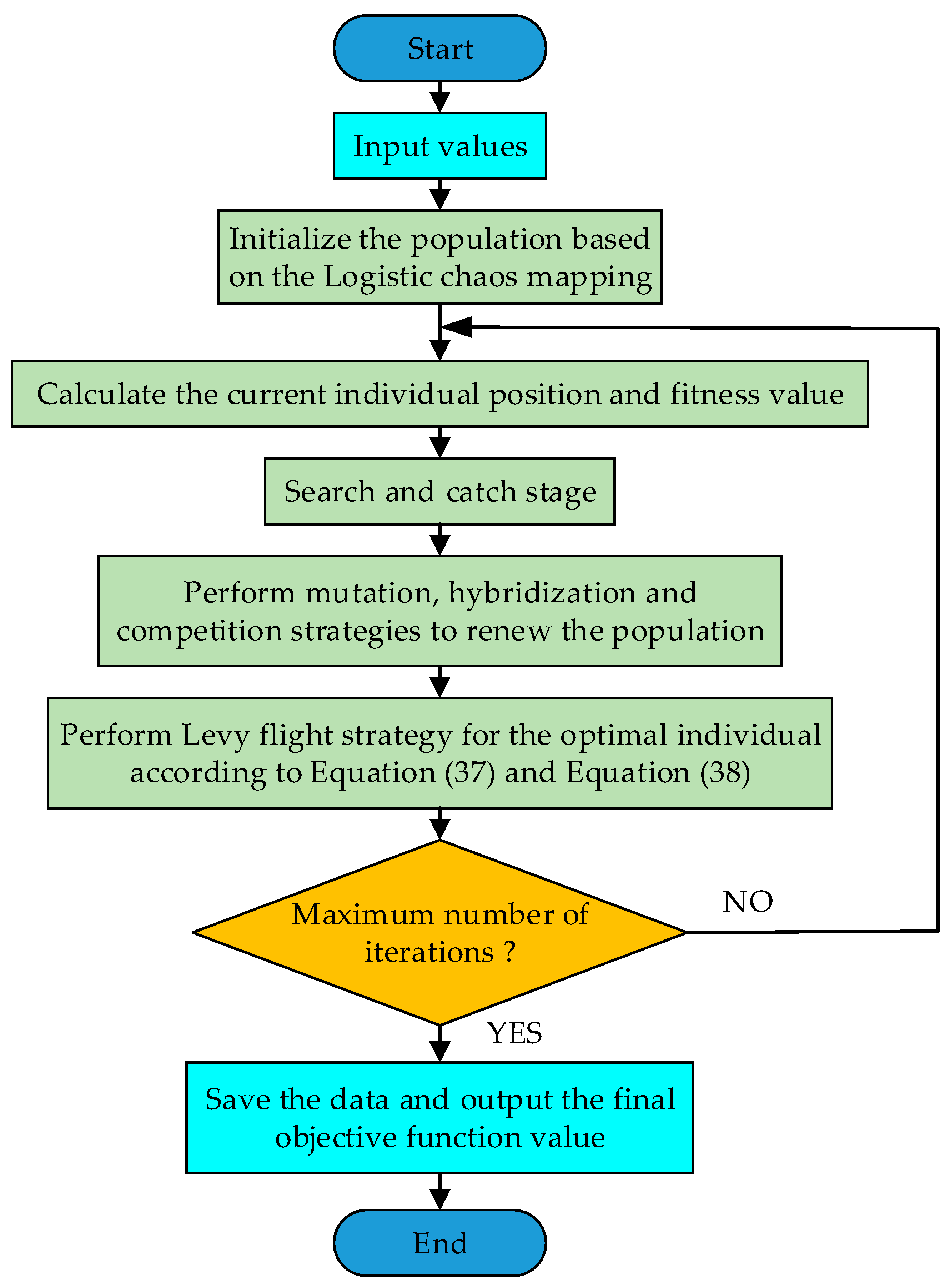
24]. The chaos strategy increases the randomness of individuals during the initialization stage, the mutation strategy increases the diversity of the population during the iteration, and the levy flight strategy can prevent individuals from falling into local extremes [
25,
26]. Therefore, by introducing the above strategies, the improved aquila optimizer (IAO) algorithm is proposed. In this study, the IAO algorithm is applied as the optimization algorithm, and the comparison results are better than those of the compared algorithms.
In this study, we analyze the form of energy storage battery configuration of traditional CCHP system and innovatively propose a storage battery configuration scheme. By introducing the improved strategies into the original AO algorithm, the IAO algorithm is proposed and used for the optimal configuration of the CCHP microgrid model. The addition of photovoltaic power generation equipment improves the sustainability and environmental friendliness of the CCHP microgrid. The proposed method reduces the power supply pressure of the grid, improves the profits of operators, and is conducive to promoting the development of clean energy, alleviating the energy crisis.
The research hypothesis of this study is to reduce the economic cost and exhaust emissions of the CCHP system through optimizing the configuration of the CCHP multi-microgrid system based on ESS service. Through the establishment of ESS by operators, the dependence of the CCHP system on the grid decreases, and the operator makes a profit by providing electrical energy services to the CCHP system. The main work and contributions of this study can be summarized as follows: (1) establishing an optimal configuration model symmetrically considering the economic and environmental benefits of ESS and the CCHP system; (2) proposing the IAO algorithm for optimal system configuration based on the AO algorithm; (3) the proposed algorithm has better optimization performance compared to the original AO algorithm; (4) reducing the dependence of the CCHP system on the grid by establishing ESS; (5) a new energy storage configuration scheme is proposed, which is beneficial to the economic and environmental protection and stable operation of the CCHP system.
The rest of this study is organized as follows:
Section 2 briefly analyzes the literature related to the design and optimal configuration of CCHP systems.
Section 3 describes the system model proposed in this study.
Section 4 describes the original algorithm and the improvement process.
Section 5 conducts an actual case study.
Section 6 discusses the implications of this study. Finally, conclusions are provided.
2. Literature Review
Conventional power plants are used at about 30% efficiency for fuel energy, with most of the remaining energy lost in the form of waste heat [
27]. After more than a century of development, the CCHP system has been proven to be an efficient and energy-efficient device operation mode [
28]. The advancement of technology has gradually changed the fuel source and energy circulation mode of CCHP systems. Nami et al. [
29] established a model of the solar-assisted biomass energy CCHP system, and analyzed the key factors of system performance optimization. The results show that the energy provided by the system can meet the energy demand of household users. However, the system’s technological maturity is low, and the complexity is too high. Moreover, the literature does not evaluate the economics of the system. Wei et al. [
30] proposed a CCHP system based on proton exchange membrane fuel cells, optimized the system from the aspects of economy and environmental protection by using the improved mayfly optimizer, and obtained the system configuration that is more economical and environmentally friendly than the original algorithm. However, the system lacks clean energy and the optimization process does not consider the problem of environmental friendliness. Tonekaboni et al. [
31] applied nanofluid and porous media to a solar collector and used the collector in a CCHP system to improve the energy absorption efficiency of the system. However, the literature lacks a discussion of the economics and environmental protection of the system. Li et al. [
32] used the heat pump as the heat source of the CCHP system. Through the analysis of the primary energy saving rate, the carbon dioxide emission reduction rate, and the annual cost saving rate, the system was optimized and analyzed in practical application. However, this system lacks energy storage equipment, which will cause waste of energy. Nazari et al. [
33] investigated the effect of electric boiler, hydro storage, and heat storage tank on the scheduling problem of conventional trigeneration system. The results indicated that the use of the model could improve the profits of the system. However, this system does not contain renewable energy, and the environmental protection of the system needs to be improved. Additionally, this system does not contain energy storage devices, and the lack of energy storage devices can cause energy waste. Previous studies have optimized the design of traditional CCHP systems from the perspective of system energy source, equipment material selection, and energy circulation mode. However, due to the difficulty of promoting and applying new materials, the high economic cost of installation, and the instability of new energy sources, the above-mentioned CCHP systems are still in the theoretical research stage.
The energy crisis and environmental issues have promoted the development of clean and renewable energy, and CCHP systems with clean and renewable energy have become a new trend in recent research [
34]. Leonzio et al. [
35] used software to design and simulate a trigeneration system powered by biogas. The results showed that the system has significant improvements in power generation and carbon dioxide emissions relative to conventional CCHP systems. However, the application scenarios of biogas power generation methods are limited to rural areas and other areas, and large-scale popularization applications cannot be carried out. Dong et al. [
36] designed a CCHP system including wind power generation and photovoltaic power generation equipment as the coupling hub of the electric-gas system. Although this system is more economical than separated systems, the cost of wind turbines installation is still too high for the ordinary user, and the wind turbines are often far away from the user side, which is contrary to the installation concept of CCHP systems integrated on the user side. Zhang et al. [
37] used a multi-objective particle swarm algorithm to optimize the CCHP system containing photovoltaic power generation, so that different buildings can achieve a balance between economy and environmental protection. Compared with wind power plants, photovoltaic power generation units can be better used in most scenarios, especially in areas where large equipment and power supply from the grid cannot be installed due to geographical constraints [
38]. As a relatively mature clean power generation method, photovoltaic power generation is applied to the CCHP system model built in this study. Photovoltaic power generation equipment often needs to be used in conjunction with energy storage devices to alleviate the intermittent characteristics of power generation [
39]. However, in previous studies, energy storage devices were generally configured by the user side of the CCHP system [
40]. Considering factors such as installation costs and supporting management, the capacity configuration of the energy storage device is smaller, and it plays a less influential role in buffering and relieving the pressure on the grid. This study proposes that using the ESS operating mode, the operator can establish a large capacity of energy storage devices to serve the CCHP system. The CCHP system needs to pay only the service fee in exchange for the power usage and storage rights of the ESS.
The establishment of ESS increases the difficulty of optimizing the configuration of the CCHP system. Mathematical programming and intelligent optimization algorithms are two commonly used methods for optimizing the configuration. Compared to mathematical programming methods, the use of intelligent optimization algorithms does not require extensive mathematical proofs or changing nonlinear terms in the original model [
41]. In the previous studies, GA and PSO have often been used in the optimal configuration and scheduling of the system [
42,
43]. However, the original algorithm has unstable performance and is easy to fall into local extremums, which has spawned scholars to improve the algorithm and produce new algorithms. Wang et al. [
44] introduced the chaos and elite strategies into the original PSO algorithm, which improved the search range and search ability of the original algorithm. Cao et al. [
2] replaced the random parameter β in the original owl search algorithm with a circular mapping based on the chaotic mechanism to improve the premature convergence problem of the original algorithm. Abualigah et al. [
23] proposed the AO algorithm by simulating the process of finding, tracking, and capturing prey by the aquila. The AO algorithm has been applied to optimize scheduling, parameter tuning, and feature extraction, and has shown superior performance to other algorithms [
45,
46]. However, when the AO algorithm deals with the multi-variable and multidimensional optimal configuration model proposed in this study, there are still problems of slow convergence speed and low convergence accuracy similar to other algorithms. Therefore, this study proposes the IAO algorithm by improving the different stages of the original AO algorithm.
3. System Description
The structure of the CCHP multi-microgrid system combined with ESS is shown in
Figure 1. In this study, the number of the CCHP microgrid is three. Considering the relevant policy restrictions and technical demands, the CCHP system is stipulated not to sell electricity to the grid. The system can be divided into power supply equipment, heating equipment, and cooling equipment. Among them, the power supply equipment includes photovoltaic generator unit (PV), micro turbine (MT), and energy storage station (ESS). Heating equipment includes gas boiler (GB), heat recovery (HR), heat exchanger (HE), and thermal storage tank (TST). Cooling equipment includes electric chiller (EC) and absorption chiller (AC). The mathematical model of the main equipment of the system is described below.
3.1. Equipment Description
3.1.1. Power Supply Equipment
(1) Photovoltaic power generation model.
Photovoltaic power generation is introduced into the CCHP system as a clean power generation method. It converts solar energy into electrical energy through the photovoltaic effect. The PV output electrical energy is expressed as follows:
where,
Ppv denotes the power output of PV,
Npv denotes the installed capacity of PV,
Gpv and
Tpv denote the solar irradiation intensity received by photovoltaic panels and the surface temperature of photovoltaic panels,
GSTC and
TSTC denote the solar irradiation intensity received by photovoltaic panels and the surface temperature of photovoltaic panels under standard test conditions, taking values of 1000 W/m
2 and 25 °C, and
k denotes the correlation coefficient.
(2) Micro turbine model.
MT is not only responsible for supplying electricity to the load, but the waste heat generated will also be further utilized through HR. The expression of MT output electricity is as follows:
where
Pmt denotes the electrical power output of MT,
Fmt denotes the consumption volume of natural gas,
α is the calorific value of natural gas with a value of 9.7 kWh/m
3, and
denotes the power generation efficiency of MT.
(3) Energy storage station model.
The energy storage station is one of the crucial devices in the system. The regulating effect of ESS further improves the performance of the system. Meanwhile, ESS operators can make a profit.
where
and
denote the power of ESS at time
t and
t − 1,
denotes the self-discharge rate of ESS,
and
denote the power purchased and sold by ESS from the CCHP system at time
t, and
and
denote the charging efficiency and discharging efficiency of the energy storage battery.
3.1.2. Heating Equipment
(1) Gas boiler model.
GB plays a crucial role as the final guarantee of heating energy. GB will produce heat when the rest of the equipment cannot meet the heat demand of the user. The expression for its heat generation is as follows:
where
Hgb denotes the heat generated by GB,
Fgb denotes the consumption volume of natural gas, and
denotes the heat production efficiency of GB.
(2) Heat recovery model.
HR makes full use of the fuel consumption of MT. It recovers the waste heat generated by MT in the process of producing electricity. The mathematical expression of HR is as follows:
where
Hhr denotes the heat recovered by HR from MT and
COPmt denotes the correlation coefficient of heat production by MT.
(3) Heat exchanger model.
HE connects the heat production of the system with the heat load. The mathematical expression for HE is as follows:
where
Hhe denotes the heat required by HE,
Hload denotes the heat load demand of the user, and
denotes the efficiency of HE.
(4) Thermal storage tank model.
TST is a buffering device for heat. TST is preferentially used to store and release excess heat and lack of heat of the system. The state expression of TST is as follows:
where
and
denote the heat of TST at time
t and
t − 1,
denotes the self-release rate of TST,
and
denote the heat stored or released at time
t, and
and
denote the efficiency of TST in storing and releasing heat, respectively.
3.1.3. Cooling Equipment
AC and EC produce cooling to meet the demand of the user. Their mathematical expressions are shown as follows:
where
Cac and
Cec denote the cold generated by AC and EC,
Hac denotes the heat consumption of AC,
denotes the cooling efficiency of AC,
Pec denotes the power consumption of EC, and
COPec denotes the cooling coefficient of EC.
3.2. Problem Description
This study aims to optimize the configuration of the CCHP multi-microgrid system combined with ESS. In the solution process, both the economic and environmental protection of the CCHP system and the profitability of the ESS should be satisfied. The decision variables, objective function, constraints, and operating scheme are described as follows.
3.2.1. Decision Variables
The decision variables are as follows:
where
Npv,
Nmt,
Ngb, and
Ntst denote the installed capacity of PV, MT, GB, and TST,
Ngrid denotes the upper limit of power purchased from the grid,
Nbat denotes the capacity of storage batteries to be allocated, and
r denotes the ratio of EC cooling production to the cooling load.
3.2.2. Objective Function
The objective function considers the net investment cost of the CCHP system, the cost of consumed natural gas, the ESS service charge, the cost of electricity purchased from the grid, and the cost of waste gas treatment.
where
F denotes the value of the objective function,
CI denotes the daily investment cost of the equipment,
CF denotes the cost of consuming natural gas,
CS denotes the service cost of ESS,
CG denotes the cost of purchasing electricity from the grid, and
CE denotes the cost of treating the waste gas. The specific cost expressions are as follows:
where
β denotes the investment recovery coefficient,
Ni denotes the installed capacity of the
i-th equipment,
Ci denotes the unit investment cost,
L denotes the life of the equipment, and
a denotes the discount rate, taking the value of 0.08.
where
Cf denotes the price of natural gas,
denotes the electricity purchases from the grid at time
t, and
is the price of electricity at time
t.
where
and
represent the electricity sold and bought by ESS to the CCHP system at time
t,
and
represent the prices of electricity sold and purchased by ESS at time
t, and
represents the service charge of ESS taking the value of 0.0079
$/kWh.
where
and
are the electricity and heat waste at time
t,
λ is the penalty factor,
,
, and
are the electricity generated by MT, the heat produced by GB, and the electricity purchased from the grid at time
t,
,
, and
are the emissions of the
g-th pollutant gas emitted by MT, GB, and the grid, and
denotes the cost required to treat the
g-th pollutant gas.
3.2.3. Constraints
The constraints include the balance of electricity, heating and cooling, and the capacity limits of the equipment.
(1) Equality constraints.
The electricity balance is as follows:
where
indicates the required electricity of the system at time
t, and
and
are the shortage and waste of electricity at time
t.
The heating balance is as follows:
where
and
represent the shortage and waste of heat at time
t, respectively.
The cooling balance is as follows:
where
denotes the cooling load required by the user at time
t.
(2) Inequality constraints.
The inequality constraints are mainly the capacity limits of the equipment. The inequality constraints involved in this study are listed in
Table 1.
3.3. Operation Schemes
The addition of storage batteries improves the utilization of electricity. However, the configuration of storage batteries alone will increase the investment cost. Additionally, the smaller configuration size has less effect on electricity regulation. Therefore, this study proposes a CCHP system based on ESS service. The earnings of ESS come from two sources. First, the electricity used and stored in ESS is calculated for each CCHP system: charging in the form of electricity sales and purchases. Second, ESS charges a service fee for the electricity used and stored by the CCHP system. In this study, two other operation schemes are chosen for comparison. The three operation schemes are described as follows.
Each CCHP system operates independently without configuring energy storage batteries, and the ESS services the CCHP system. Excess power is sold to ESS when PV and MT generation is sufficient. Conversely, electricity is first purchased from ESS when there is insufficient electricity. If the ESS does not have enough electricity, the customer purchases the shortage from the grid.
Each CCHP system operates independently and is equipped with energy storage batteries. The operation process is similar to scheme 1. However, under this scheme, the cost of energy storage batteries needs to be included in the net investment cost.
Each CCHP system operates independently without the configuration of energy storage batteries. When PV and MT generation is sufficient, surplus electricity is wasted. Conversely, electricity is purchased from the grid if there is insufficient generation.
The heating and cooling load demands are met in the same way for the three operating schemes. First, it is determined whether the waste heat recovered by HR meets the system heat demand. If the waste heat is larger than the demand, the excess heat is saved in the TST. If the waste heat is insufficient, TST is given priority for heat release. When TST still cannot meet the demand, GB starts heat production.
5. Case Study
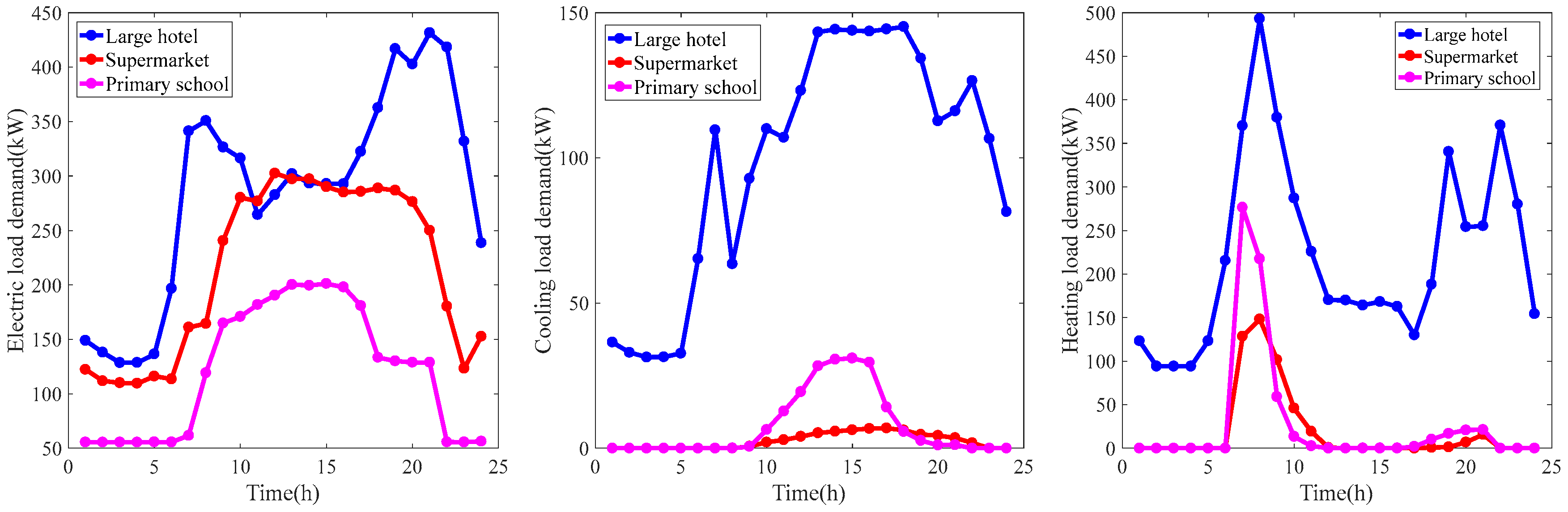
To evaluate the effectiveness of the operation scheme and optimization algorithm proposed in this study, the load data of a large hotel, a supermarket, and a primary school in 16 typical buildings provided by the US Department of Energy Building Technologies program are selected as cases for analysis [
47,
48].
Figure 3 shows the load curves of the three buildings.
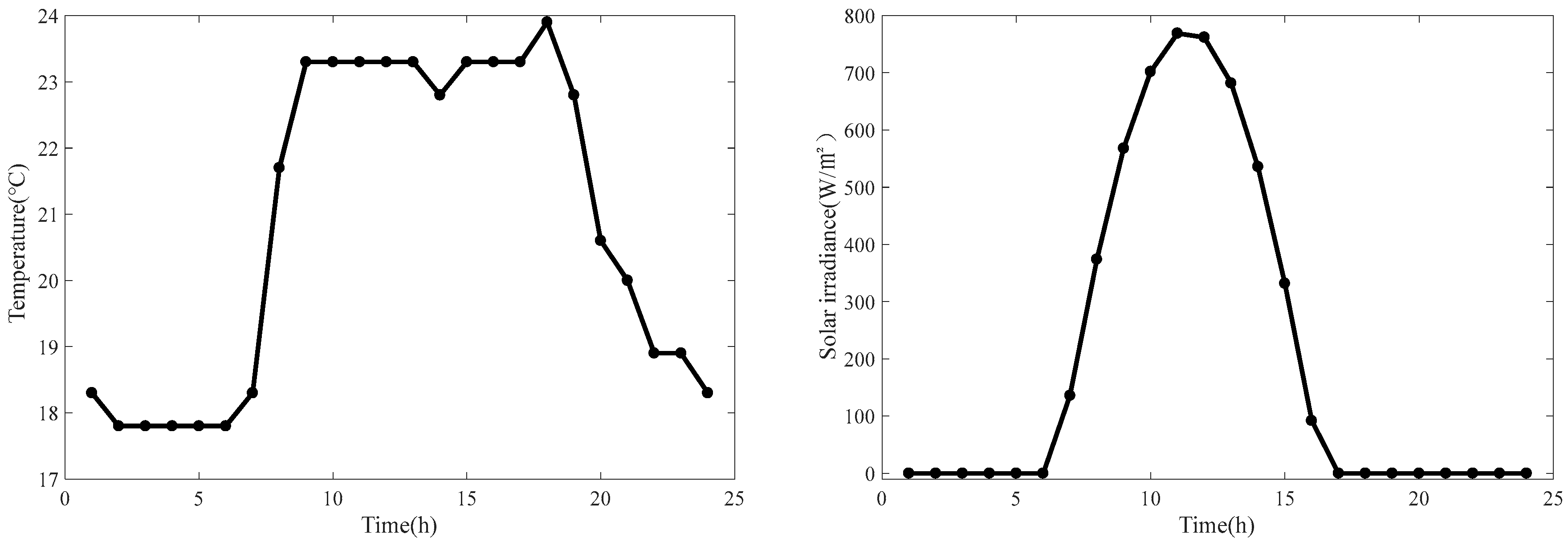
Figure 4 shows the temperature and solar irradiance curves.
Table 2 lists the relevant parameters of the equipment in the system.
Table 3 shows the installation cost and life of the equipment.
Table 4 shows the price of electricity and natural gas.
Table 5 shows the pollutant gas emission factors and treatment costs.
In this study, the population size of the algorithm is 30, and the number of iterations is 500. The experiments were performed on MATLAB R2016b software. The computer is configured with Intel® CoreTM i5-6200U, 2.4 GHz, 12 GB RAM, and is made in China.
5.1. Optimization Results
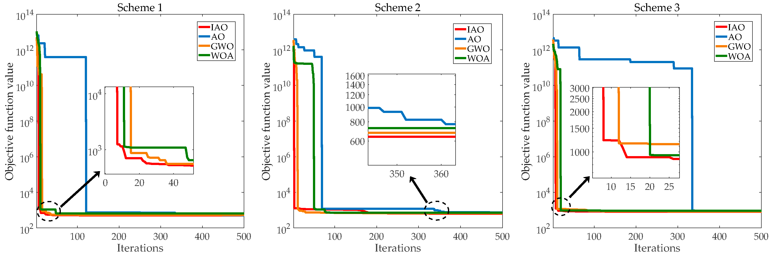
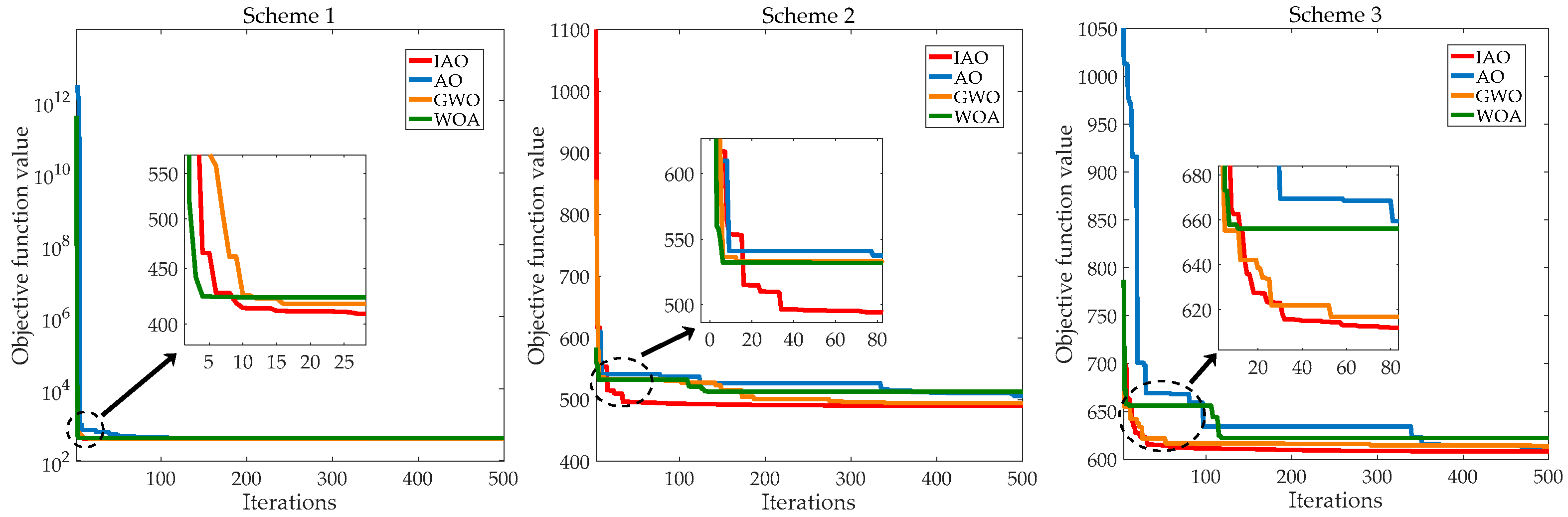
This study aims to improve the economy and environmental protection of the system by combining ESS. By arranging the energy flow of the CCHP system properly, it can reduce the pressure on the grid and the pollutant gas emissions. Meanwhile, ESS makes a profit by serving the CCHP system. The improvements to the original AO algorithm have improved its performance. The gray wolf optimizer (GWO), the whale optimization algorithm (WOA), and the original AO algorithm are selected as comparison algorithms to verify the performance of the IAO algorithm. Based on the different schemes, four algorithms are used to optimize the system, respectively.
Section 3.3 provides a specific description of the schemes. The results are the average values of 50 runs based on the program. The convergence curves of the four algorithms are shown in
Figure 5,
Figure 6 and
Figure 7.
The analysis of the convergence curves reveals the following conclusions.
(1) The convergence speed of the IAO algorithm is significantly improved compared to the original AO algorithm. At the iteration number of 100, the IAO algorithm can already converge to a smaller value. Moreover, the convergence speed of the IAO algorithm is faster compared with GWO and WOA.
(2) The convergence accuracy of the IAO algorithm is higher. When reaching the maximum number of iterations, the convergence value of the IAO algorithm is smaller than the convergence values of the other three compared algorithms.
(3) For the same place and optimization algorithm, the convergence values of the iterative curves based on different schemes have significant differences. Specifically, the convergence value of the iteration curve is smaller when the system is operating with scheme 1.
The above results show that the improvement to the AO algorithm is effective. The convergence speed and convergence accuracy of the IAO algorithm are better than the comparison algorithms. Meanwhile, the operation scheme proposed in this study has better economy and environmental protection.
Table 6 shows the objective function values and pollutant gas emissions for different operation schemes.
The data in
Table 6 more intuitively show the effectiveness of the optimal configuration using the IAO algorithm. For different places and different schemes, the proposed algorithm can obtain the minimum objective function value. Therefore, the IAO algorithm has better search capability and stability than other algorithms. Meanwhile, the calculation shows that the daily economic cost obtained by the IAO algorithm is lower when the systems of the three places are operating with scheme 1. Compared with the cost of scheme 2, the values decreased by 20.54%, 17.95%, and 25.46%, respectively. Compared with the cost when the systems of three places are operating with scheme 3, the values decreased by 37.88%, 33.88%, and 43.38%, respectively. The values for pollutant gas emissions decreased by 16.8%, 28.57%, 32.93% and 32.45%, 43.37%, 49.39%, respectively. The results indicate that the construction of ESS is beneficial to the operation of the CCHP system. Therefore, scheme 1 achieves both economic and environmental improvements for the user side of the CCHP system.
This study aims to take advantage of the scale of ESS to improve the performance of the CCHP system. At the same time, the ESS operator can be profitable.
Table 7 shows the capacity configurations and daily investment costs of the energy storage batteries and the revenue of the operator.
From the data in
Table 7, it can be found that compared to the CCHP system in scheme 2, which is configured with energy storage equipment alone, in scheme 1, ESS can be configured with larger capacity energy storage batteries. Compared with scheme 2, although the form of building ESS will increase the investment cost in energy storage equipment, the merchant still has room for profit. Therefore, the configuration of energy storage equipment proposed in this study is feasible. We consider the profitability of the merchant, and also take into account the economy and environmental protection of the CCHP system. A win-win situation can be achieved by operating ESS with multiple CCHP systems.
5.2. Scheduling Results
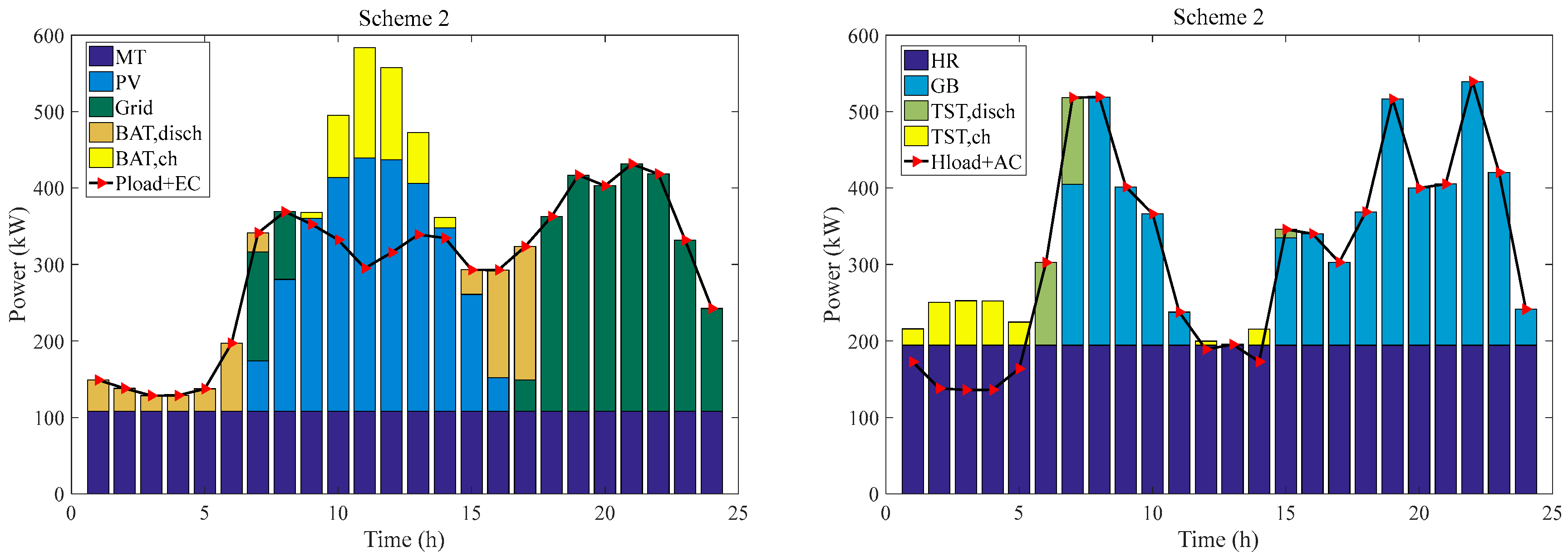
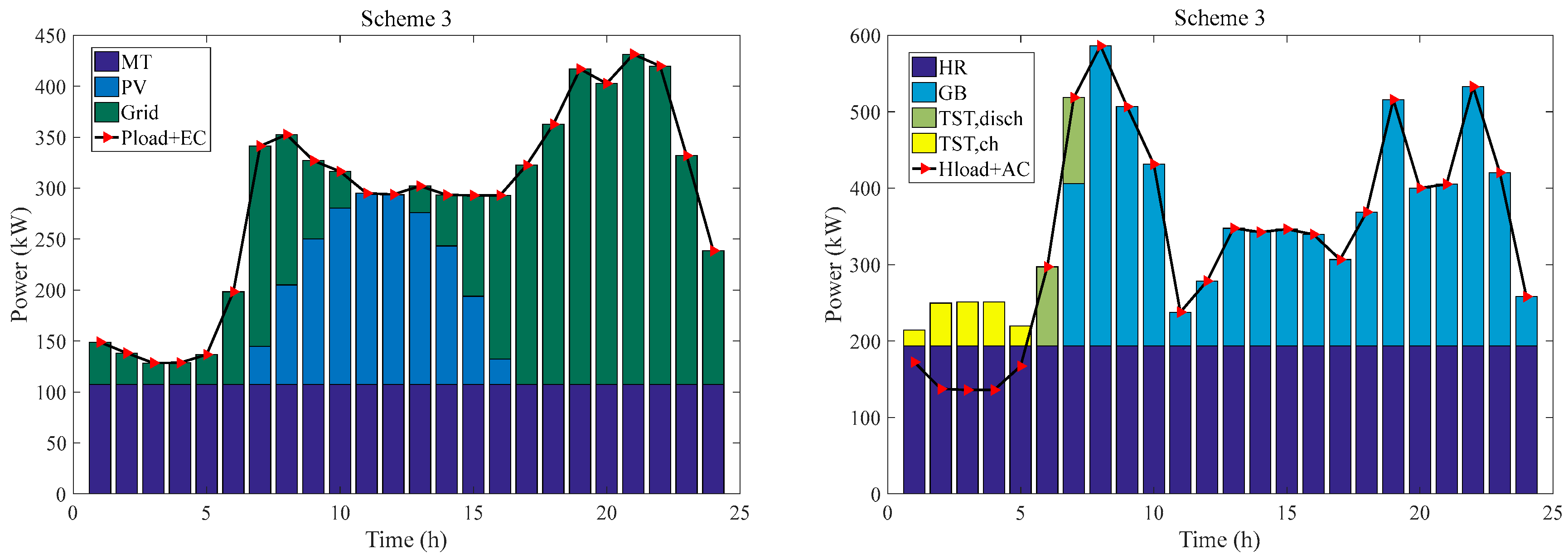
Taking Place 1 as an example,
Figure 8,
Figure 9 and
Figure 10 show the electricity balance and heating balance of the CCHP system obtained by the IAO algorithm under different schemes.
The electricity balance shows that all three operating schemes can meet the electricity demand of Place 1 during the day. For scheme 1, from 01:00 to 19:00, the ESS regulates the electrical energy balance of the CCHP system by selling and purchasing electricity. ESS and MT work together to meet the electricity demand of the system when weather conditions do not allow for PV generation. When the PV can generate electricity, ESS, MT, and PV together meet the electricity balance of the system. From 20:00 to 24:00, ESS, MT, and the grid work together to meet the electricity demand of the system. For scheme 2, the scale of self-configured energy storage equipment in CCHP systems is smaller. Therefore, its adjustable range for electricity reduces accordingly. As a result, the electricity required from the grid increases. For scheme 3, the lack of energy storage equipment prevents the system from configuring large-capacity photovoltaic power generation equipment. The system still requires a significant amount of electricity from the grid to meet demand. In summary, ESS can guarantee the electricity balance of the CCHP system by taking advantage of its scale. I In addition, it makes a profit by selling electricity and charging service fees. Meanwhile, the CCHP system reduces economic costs by eliminating energy storage equipment and selling surplus electricity.
The heating balance shows that all three operating schemes can meet the heating demand of Place 1 during the day. The heat production from 1:00 to 11:00 and 15:00 to 24:00 is essentially the same for the different equipment under the three schemes. From 12:00 to 14:00, PV produces sufficient electricity. Due to the electricity regulation by energy storage equipment, the system can be configured with higher capacity photovoltaic generation equipment when operating through scheme 1 and scheme 2. As a result, the percentage of the cooling load allocated to EC will increase. Consequently, less heat will be required to meet the cooling load, indirectly reducing the heat production of GB, thus reducing the emission of polluting gases. On the contrary, when the system is operating with scheme 3, the capacity of the configured photovoltaic power generation equipment is less due to the lack of energy storage equipment. Hence, EC receives less electricity and reduces its cooling production, and more heat is needed to meet the demand for AC. More heat needs to be provided by GB, thus increasing the emission of polluting gases.
Table 8 shows the electricity generated by different equipment under the three operating schemes. With Scheme 1 operation, the PV and the grid provide 34.38% and 15.08% of the total electricity. When run with scheme 2, the corresponding values are 29.19% and 28.27%. When run with scheme 3, the corresponding values are 17.92% and 44.76%, respectively. The percentage of electricity provided by energy storage equipment under the three schemes is 17.95%, 8.04%, and 0%, respectively. Therefore, for the same load demand, increasing the proportion of PV can reduce the pressure on the grid to supply electricity. Compared with scheme 2 and scheme 3, the electricity provided by the grid is decreased by 43.29% and 61.09% when operating with scheme 1. The intermittency of PV needs to be balanced by energy storage equipment. ESS purchases excess electricity during the peak generation period of PV, and sells electricity preferentially when the system lacks electricity. The combined model of ESS and PV produces almost zero pollution in the production and utilization of electricity. The scheme also makes more sense for environmental protection.
In summary, the CCHP system based on ESS service proposed in this study has more competitive advantages. The system is more economical and emits fewer pollutant gases. Moreover, ESS has room for profitability. The energy storage space provided by ESS can better alleviate the intermittency of PV, regulate the electricity balance of the system, and reduce the pressure on the grid.
6. Discussion
Compared with the original AO algorithm, the improved algorithm improves the convergence speed and convergence accuracy and can obtain better objective function values in fewer iterations. Based on the better objective function value, it can be concluded that the economic cost of the system is reduced and the exhaust emissions are reduced. This study contributes to the optimal configuration of the CCHP system. The optimal configuration model based on the IAO algorithm has played an essential role in influencing and promoting the related fields.
In terms of reducing economic costs, this study proposes a new energy storage equipment configuration scheme. Through the coordination of energy storage equipment and photovoltaic power generation equipment, the demand of the system for grid power supply is reduced. Therefore, the exhaust gas emissions from grid power generation are reduced, thus symmetrically reducing the economic investment required for exhaust gas treatment. Meanwhile, the reduced power supply can reduce the pressure on the grid and improve the flexibility of the CCHP system. The CCHP system can still maintain a relatively stable operation when an accident occurs on the grid. In addition, through the construction of ESS, the intermittency of photovoltaic power generation can be further alleviated, and the ESS operator can still get the revenue to keep operating normally.
In terms of exhaust emissions, the system emits the least quantity of exhaust gases when operating with the scheme proposed in this study. The quantity of the exhaust emissions is linked to the cost required to treat the exhaust gas. In addition, the reduction of exhaust emissions can also decrease the damage to the atmosphere. With lower emissions, the cost of treating the exhaust gas is reduced, thus saving the economic investment of the system. As an important part of the ecological environment, reducing exhaust gas pollution and maintaining a clean atmosphere can promote the green cycle of the entire ecosystem. This study provides a sustainable and effective new idea for the green development of the microgrid.
This study makes full use of clean energy to reduce the consumption of non-renewable energy sources. Under the premise of meeting the load requirements from users, this study is committed to finding an effective system configuration solution. In the context of energy crisis and environmental problems, energy conservation and emission reduction are important issues that both companies and individuals cannot ignore. The CCHP system has raised the utilization rate of energy to a new level. The emergence of CCHP systems provides an effective implementation way for energy cascade utilization. Based on the traditional CCHP system, the introduction of photovoltaic power generation equipment can improve the environmental protection benefits of the system and save fossil fuels. Considering the current rising prices of non-renewable energy, reducing the consumption of natural gas raw materials and making full use of clean power generation methods can reduce dependence on imported energy. This study provides an effective way to reduce energy consumption and reduce carbon emissions, which can promote sustainable development.
7. Concluding Remarks
This study designed a CCHP system including photovoltaic power generation equipment and energy storage equipment. According to the characteristics of the two typical configuration schemes of energy storage equipment, the operation scheme based on ESS service was proposed, and a mathematical model considering economy and environmental protection was established. Additionally, the IAO algorithm was proposed by introducing improved strategies. The optimal configurations of the system under different operating schemes were obtained by the IAO algorithm and other compared algorithms. The conclusions are as follows.
(1) The IAO algorithm has better seeking ability than the original algorithm and other compared algorithms. The IAO algorithm has a faster convergence speed and higher convergence accuracy. When other conditions are consistent, using the IAO algorithm to optimize the system can get better results.
(2) The operating scheme proposed in this study is more feasible. For the system in the same place when operating with three different schemes, scheme 1 shows a greater advantage in terms of economy and environmental protection. Compared with scheme 2 and scheme 3, the daily economic cost of the three places decreased by 20.54%, 17.95%, 25.46% and 37.88%, 33.88%, 43.38%, respectively, and the pollutant gas emissions decreased by 16.8%, 28.57%, 32.93% and 32.45%, 43.37%, 49.39% respectively.
(3) Whether to configure energy storage equipment and how to configure energy storage equipment directly affect the configured capacity of PV in CCHP microgrid, thus affecting the pressure of power grid supporting system. Although the three operation schemes can meet the load demand of the system, their economy is different. Scheme 1 can configure a larger scale of PV to reduce the power supply pressure of power grid by matching the PV with the ESS. Taking Place 1 as an example, the electricity provided by the grid is decreased by 43.29% and 61.09%, respectively, when operating with scheme 1 compared to scheme 2 and scheme 3, which improves the system’s economic performance.
We put forward a new scheme for the energy storage configuration of CCHP system, and propose the IAO algorithm to optimize the system. The proposed method reduces the power supply pressure of the grid, improves the profits of operators, and is conducive to promoting the development of clean energy, alleviating the energy crisis. However, this study has some limitations. There is only one renewable energy in the system, namely photovoltaic energy, and more kinds of renewable energy can be taken into account in future research.


