1. Introduction
Direct current (DC) motors are used in complex industrial settings such as rolling mills, elevators, robotic manipulators, and steel mills [
1,
2,
3]. They are commonly controlled through field current or armature voltage variations; however, external disturbances, uncertainties, and some non-linear characteristics affect the performance [
3]. Hence, power converters have become helpful devices that control energy and variables and allow an efficient response to these undesired events.
Common control strategies applied to power converters in industrial environments are proportional-integral (PI) and proportional-integral-derivative (PID) for their simplicity and efficiency. However, they are not very robust when dealing with uncertainties, parameter variations, and rapid load changes. The optimal parameter tuning of the PI and PID controllers applied to uncertain system models has become a difficult task to carry out, affecting the response time and accuracy of the control system.
Advanced control strategies have been proposed to improve the performance of control systems applied to DC motors, avoid unwanted noise, and enhance controller efficiency. Currently, new researchers are searching for an efficient and self-adaptive control combining PID control with other control strategies [
4] (artificial intelligence) and proposing robust, adaptive, predictive, or sliding mode controls.
For instance, in the literature, some strategies have been proposed to improve the performance of DC motor control systems powered by power converters. In [
5], a non-linear PI control is proposed to regulate the motor speed, which improves the dynamic performance of the system when disturbances and load variations are presented. A fractional-order PID (FO-PID) control with particle swarm optimization (PSO) is applied in [
6] to control the speed of a motor fed by a buck converter, which improves the efficiency of the control with less effort.
The SMC control is effective in addressing the effect of external disturbances and model uncertainties while achieving a convergence of the following error towards small values [
4,
7,
8]. However, sliding-mode controllers often exhibit chattering or high-frequency oscillations. Then, a sliding mode control approach based on perturbation observers (DOB-SMC) is proposed in [
9]. The simulation tests evidenced the effectiveness of the control system in estimating and responding to disturbances in real-time. However, when the robustness in the control action was increased, then chattering was presented.
Furthermore, the works reported in [
4,
8,
10] have focused on solving the chattering problem and improving the performance of conventional SMC. In [
4], a power function replaces the exponential approximation method for the control of permanent magnet synchronous linear motors (PMSLM). The use of an improved exponential reaching law applied in PMSM drives is discussed in [
8]. Moreover, a second-order PMSM is controlled through a global nonsingular fixed-time terminal sliding mode control (GNFTSMC) in [
10]; the results show that the system responds more smoothly and quickly, while avoiding the singularity problem.
The optimal adjustment of the parameters of the PID controllers, SMC, and its variants, constitutes one of the most relevant study topics during the last decade. The working conditions of control systems generally imply dynamic and random characteristics, to which the control system must adapt to produce adequate quality indices for stability. This issue has been addressed through metaheuristics by creating divergent strategies and evolutionary algorithms to find the best possible solution in real-time. Under this approach, speed control for a DC motor based on an SMC and an ant colony optimization algorithm was proposed in [
3]. Compared to the manual adjustment of the SMC parameters, the tuning with the optimization algorithm allows obtaining a good accurate response against large parametric variations and external disturbances.
The integration of advanced control techniques in the industry has been limited due, among others, to the complexity of the control rules and the computational cost necessary to achieve robustness against complex load torque disturbances in a DC motor. In this sense, it is required to search for a configuration that provides the benefits of linear control (easy implementation and good performance) and non-linear control (good response to uncertainties and parameter variation and dynamic adaptability of the control configuration). The balance between simplicity of implementation and robustness is one of the study objectives. Hence, the application of new control strategies in the industry is facilitated.
In this sense, the SMC with a washout filter (SMC-w) is a simple control strategy that provides good performance in the systems. The SMC-w allows the response to disturbances and offers levels of robustness against load variations [
11,
12,
13,
14]. For instance, in [
12], a power converter is controlled through an SMC-w under different types of loads such as constant impedance loads (CIL), non-linear constant power loads (CPLs), and a combination of both. In addition, bifurcation diagrams were made, representing the steady-state value of the regulated voltage and the tracking error as a function of the control parameter
, associated with the PWM controller. The results showed that the proposed strategy stabilizes the DC bus voltage faster and with a low steady-state error than conventional PID control and SMC under variable loads. In [
13], a bidirectional DC-DC buck-boost converter in a DC-charged solar battery system is controlled through an SMC-w, achieving stable operation of the DC bus and sustained power balance of the system. In addition, the transient performance of the SMC-w was compared with the conventional PID for the cases of variable solar irradiation and load changes. The SMC-w achieved a lower voltage overshoot and faster convergence of the output error to its steady state.
Bifurcation analysis allows determining a safe operating region for the controller. This analysis is treated for a controller with SMC-w in [
12,
14], by studying the robustness of a disturbance response scheme. The washout filter removes steady-state inputs and allows transient inputs to pass, ensuring that all balance points of the original system are preserved.
Although there is research evidence involving SMC-w for voltage control in microgrids. There is no evidence in the literature of its application for speed control of DC motors through inverters. In practice, the control of a DC motor is carried out in the presence of various types of loads and parameter uncertainties. The relatively high order of system dynamics also makes control design difficult. Frequently, conventional PID controllers do not offer the robustness required for these conditions [
15]. Then, several advanced control techniques for DC motor control are considered, effectively responding to uncertainties. However, these have not been widely adopted in practice either because of their complexity, high computational cost, or a significant number of adjustment parameters. Because of this, DC motor control has become a very active research area in power electronics and control theory.
Achieving a certain degree of balance between robustness and practicality is constituted as one of the most significant demands in the search for new control strategies. Research on motor control corresponds to a dynamic area of study and is of great importance given its applications in multiple fields. However, the search for increasingly efficient and optimal configurations has affected its value for practical application in the industry. Furthermore, achieving a balance between efficiency and simplicity of design constitutes a very appreciable line of study, especially for its potential application and acceptance by the industrial sector. Combining DC-DC converters with DC motors to achieve a smooth drive starting has advantages in real applications. For example, it allows a proper voltage application according to the required speed demand. However, the scope for high-performance control of these systems is limited by the influence of disturbances and uncertainties from various sources.
This research is carried out to analyze whether the properties and characteristics of the SMC-w control, such as efficient performance, robust control, and simplicity of design [
11,
12,
16,
17] are applicable to the control of permanent magnet DC motors, specifically to speed control under the effect of uncertainties and parametric variations. The achievement of control objectives with efficient performance indexes in terms of stability, settling time, and maximum overshoot can contribute to opening new perspectives and strategies to search for the complex balance between cost and robustness. Hence, the contributions of this work are the following:
- (1)
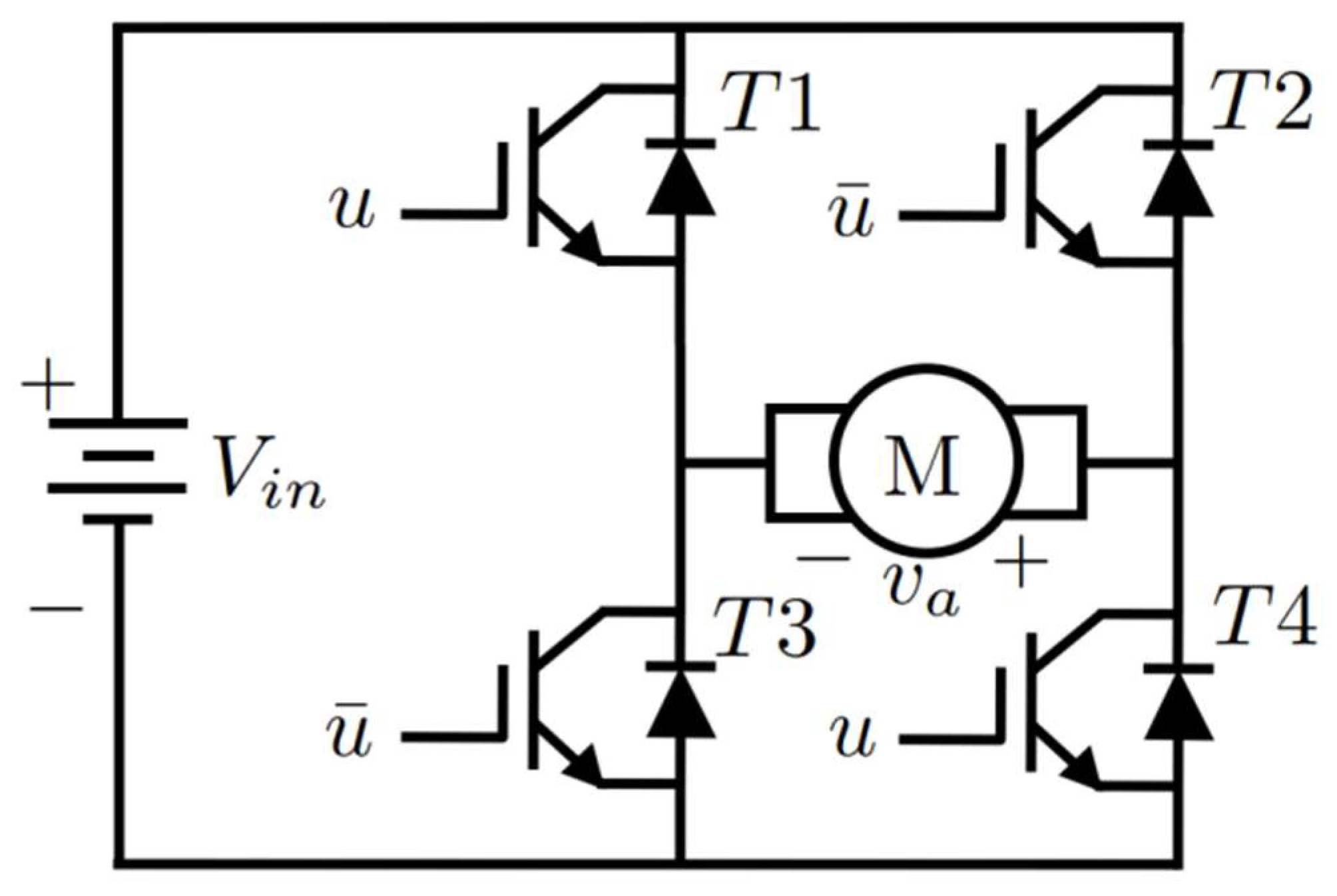
the SMC-w technique is applied to regulate the speed of a permanent magnet DC motor through a full-bridge inverter;
- (2)
the dynamic behavior of the SMC-w control is evaluated under variations of the reference signal and the load torque; and
- (3)
the efficiency of the SMC-w is analyzed in comparison with the PID controller under the same scenarios.
The paper is structured as follows.
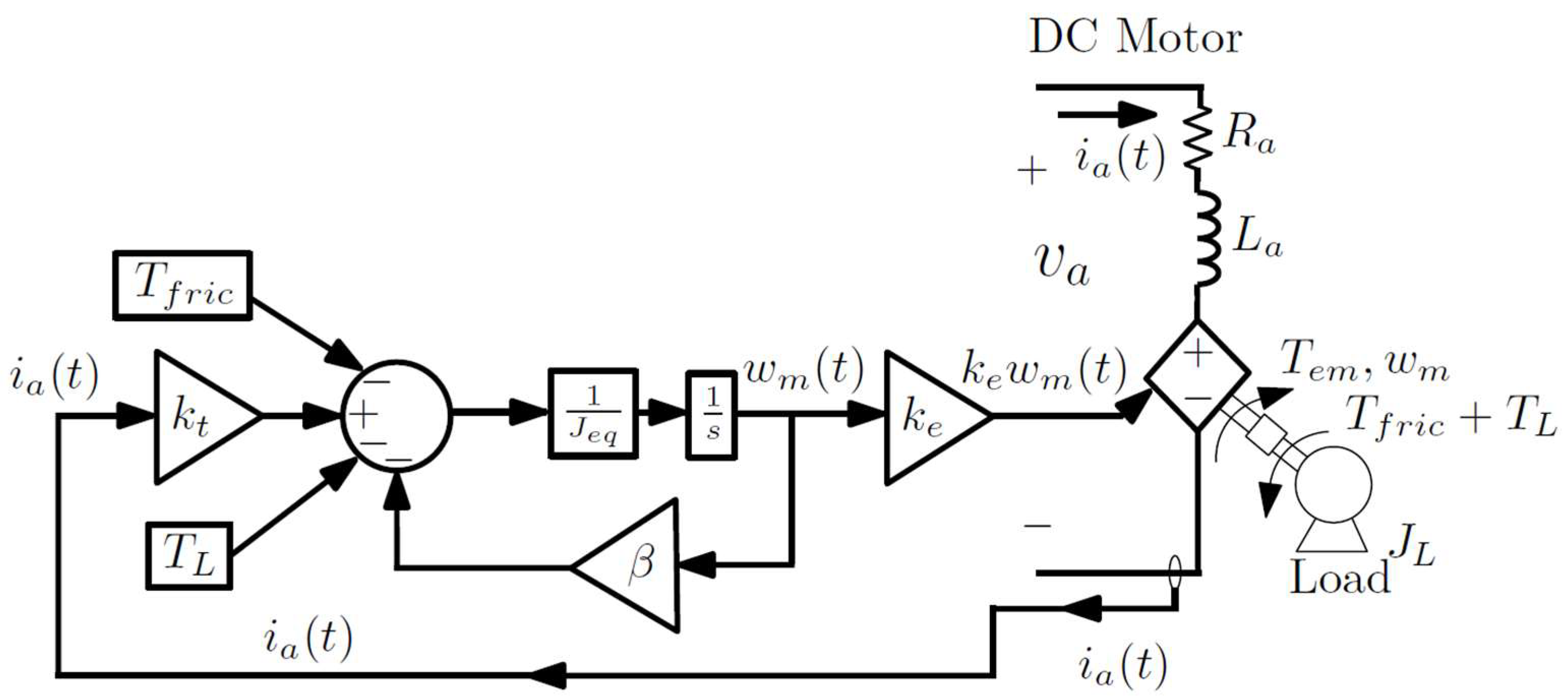
Section 2 describes the mathematical foundations of the washout filter and the SMC control. In addition, both the equivalent model of the selected DC motor and the full-bridge inverter are implemented, and the design and implementation of the SMC-w control method are carried out. In
Section 3, the results are analyzed and discussed. Finally, the conclusions and general recommendations are presented.
3. Results
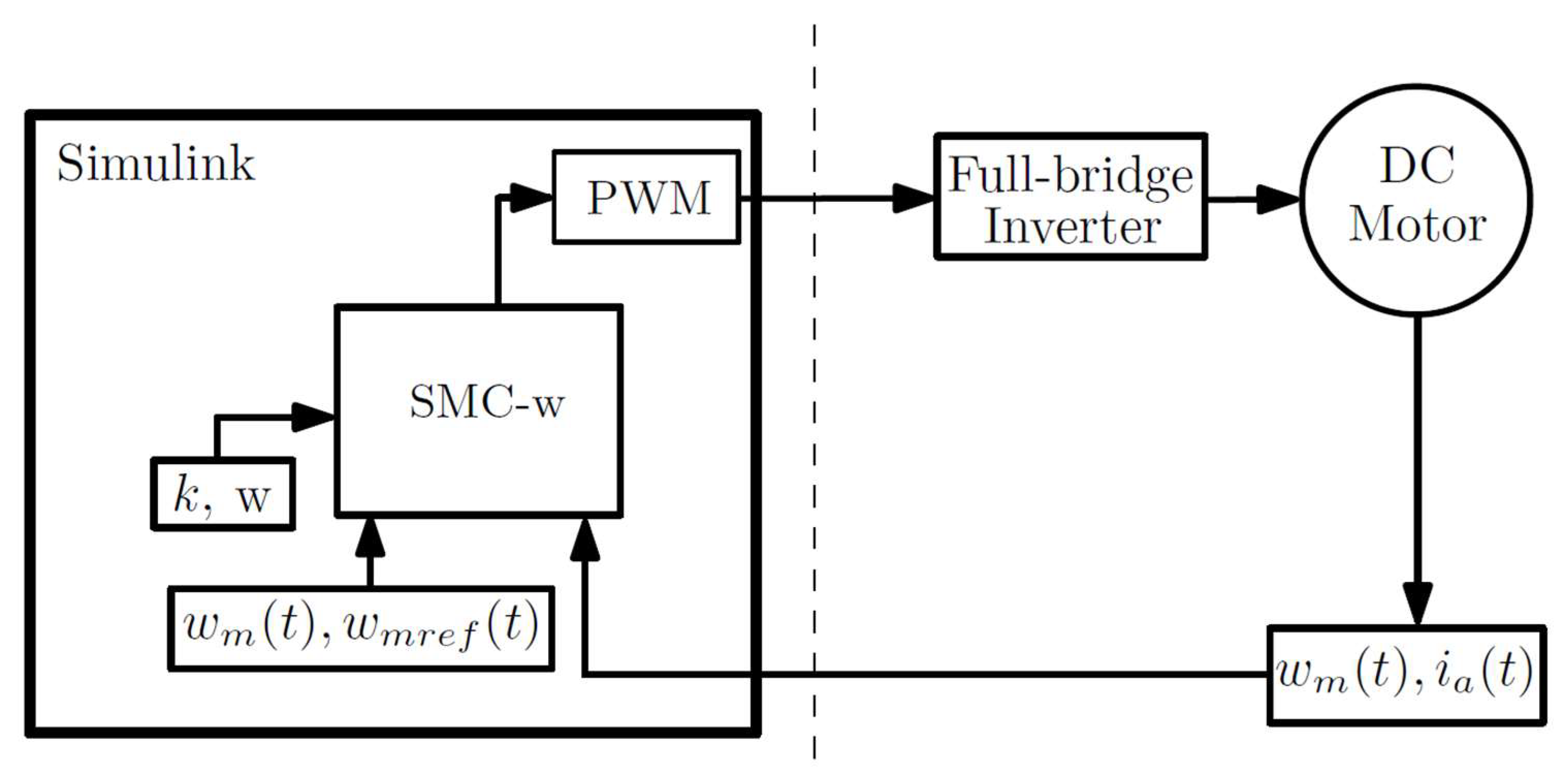
In this section, the performance of the inverter-DC motor system is analyzed using the SMC-w and compared to the results obtained with the PID control.
Table 2 describes the general parameters employed for the tests used in previous research [
19]. The parameters
and
were calculated considering the method applied in [
12]. Then, trial and error tests were performed to obtain an adjustment, looking for better performance. The values for SMC-w in the simulation are
[
11] and
.
3.1. Effect of Change in the Reference Speed Signal
The first case study evaluates the system behavior when the reference
changes. The test considered speed changes and the time of each event, as reported in
Table 3.
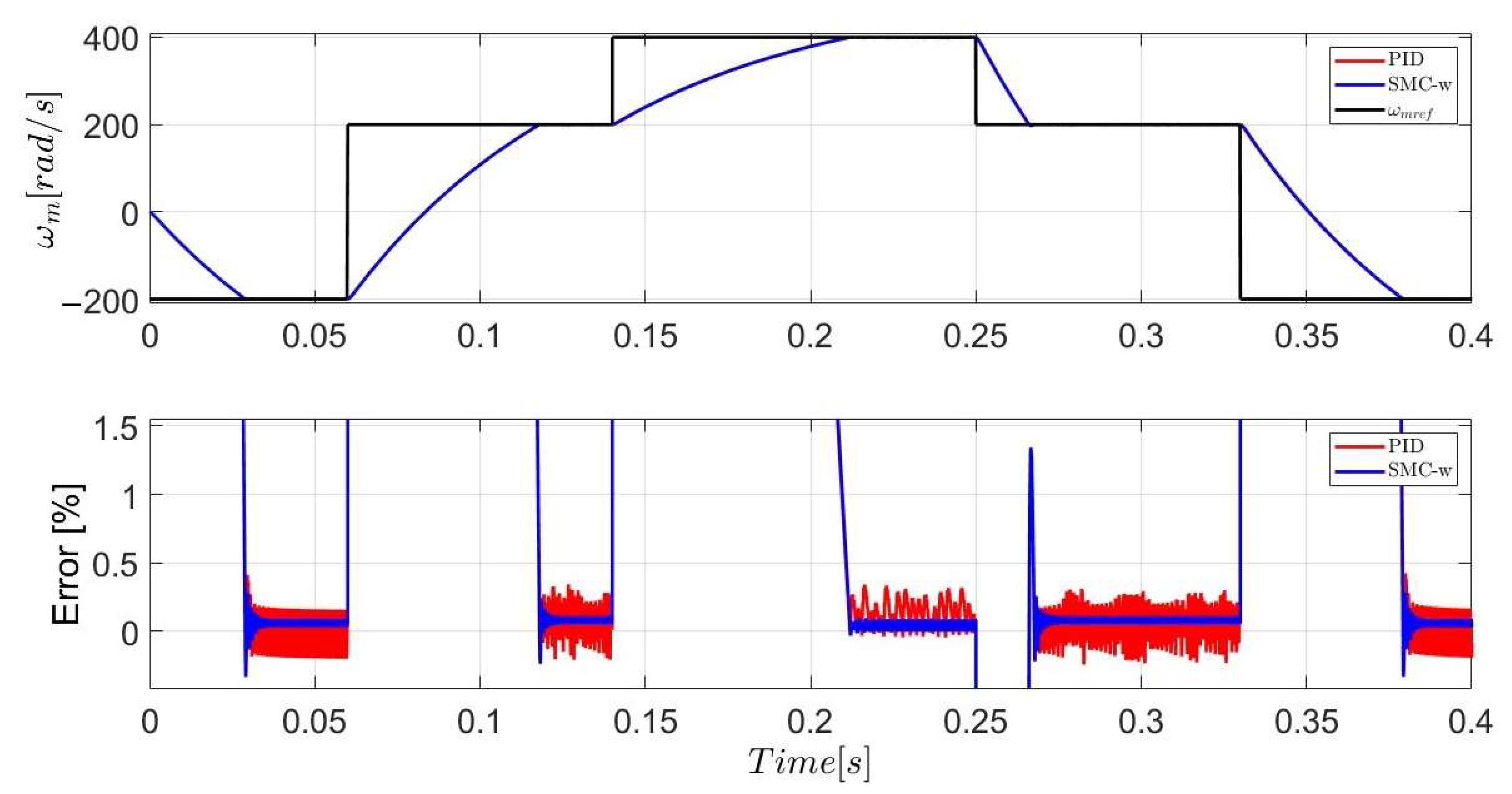
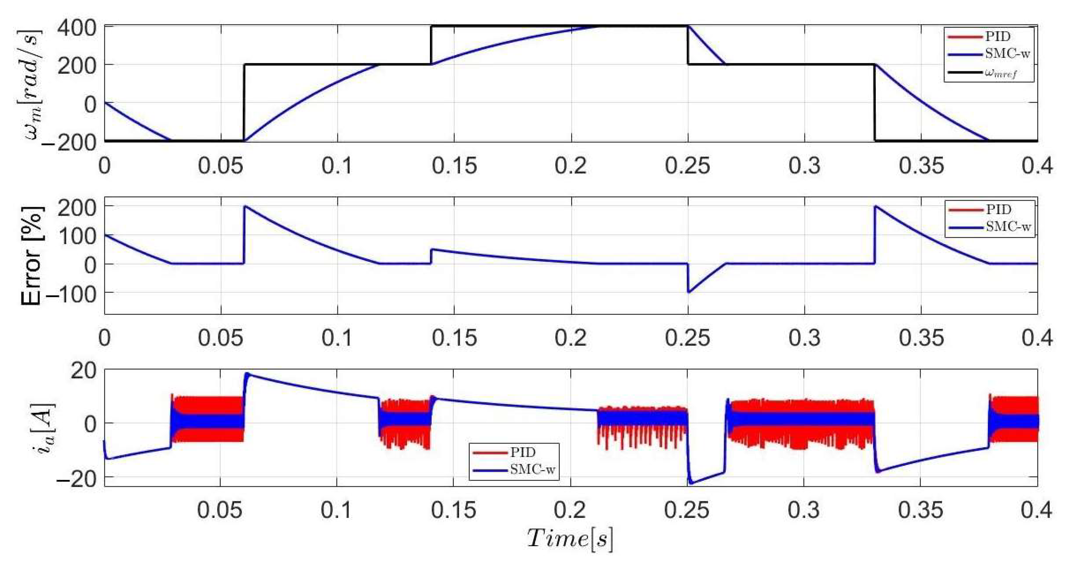
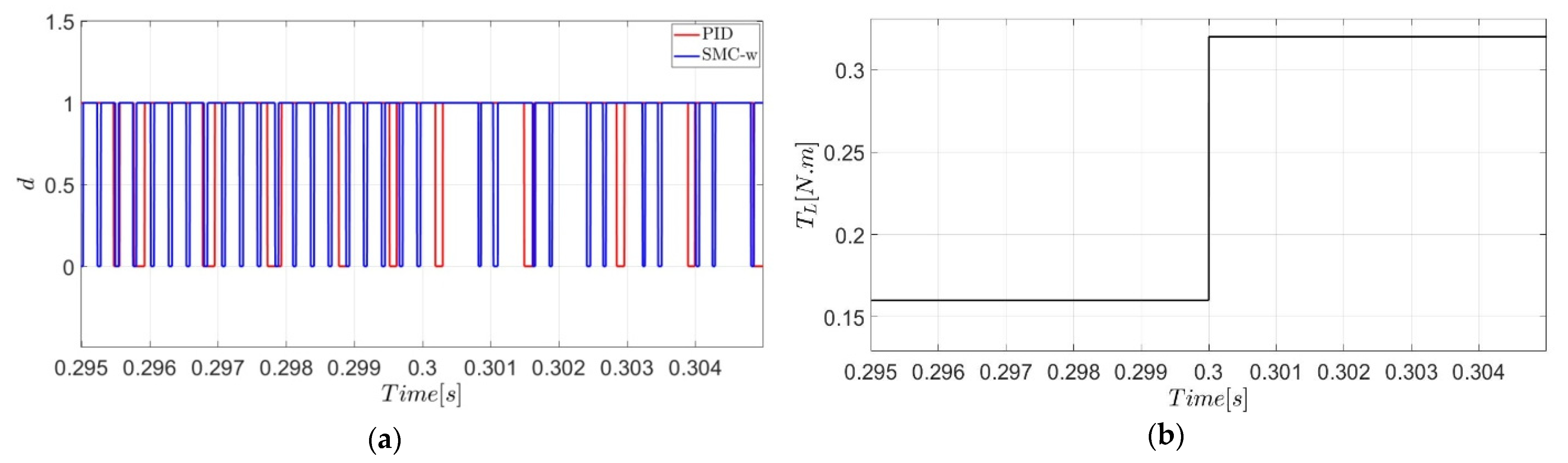
Figure 8 details the response of the system working with the SMC-w (in blue) and PID control (in red) under variations of the reference signal
(in black). Both the SMC-w and PID curves overlap due to the scale used to represent the different events. Likewise, it is possible to establish that the control variable
efficiently follows the reference signal and with a low steady-state error (<0.5%) for both control configurations (lower part of the graph). In addition, the percentage error plotted shows that the response of the SMC-w in the steady-state operation is more stable than the response obtained by the PID control.
At t = 0 s, the reference speed changes from 0 to −200 rad/s. For this reference, a settling time of 0.034 s is presented with SMC-w and 0.052 s for the PID control. The maximum overshoot is 0.33% for the SMC-w and 0.3% for the PID control (see
Figure 9). The maximum error percentage is 0.33% for the control with SMC-w (which coincides with the maximum overshoot) and 0.41% for the PID control. The steady-state error (absolute value) is less than 0.1% for the SMC-w and less than 0.2% for the PID control.
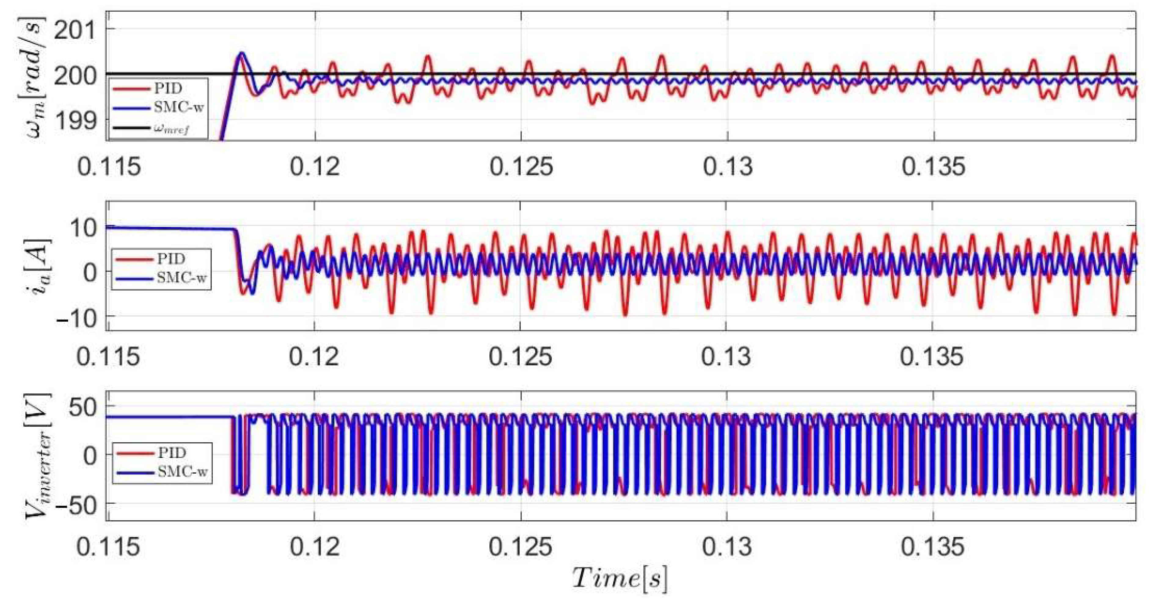
At t = 0.06 s, the reference speed changes from −200 to 200 rad/s (there is a change in the rotation of the motor). For this reference, a settling time of 0.062 s is presented for the control with SMC-w and 0.069 s for the PID control. The maximum overshoot is 0.23% for the SMC-w and 0.2% for the PID control (see
Figure 10). The maximum error percentage is −0.23% for the control with SMC-w (which coincides with the maximum overshoot) and 0.34% for the PID control. The steady-state error (absolute value) is less than 0.12% for the SMC -w and less than 0.3% for the PID control. Additionally, this figure shows that the average errors of the SMC-w and PID control converge and tend to the reference.
At t = 0.14 s, the reference speed changes from 200 to 400 rad/s. A settling time of 0.0759 s is presented for the SMC-w and 0.0904 s for the PID control. The maximum overshoot for the SMC-w is 0.03% and 0.025% for the PID (see
Figure 11). The maximum error percentage for the reference change from 200 to 400 rad/s is 0.1% for the SMC-w and 0.34% for the PID control. The steady-state error (absolute value) is less than 0.1% for the control with SMC-w and less than 0.34% for the PID control.
At t = 0.25 s, the reference speed changes from 400 to 200 rad/s. A settling time of 0.0257 s is presented for the SMC-w and 0.018 s for the PID control. The maximum overshoot for the SMC-w is 1.34% and 1.29% for the PID (see
Figure 12). The steady-state error (absolute value) is less than 0.12% for the SMC -w and less than 0.32% for the PID control.
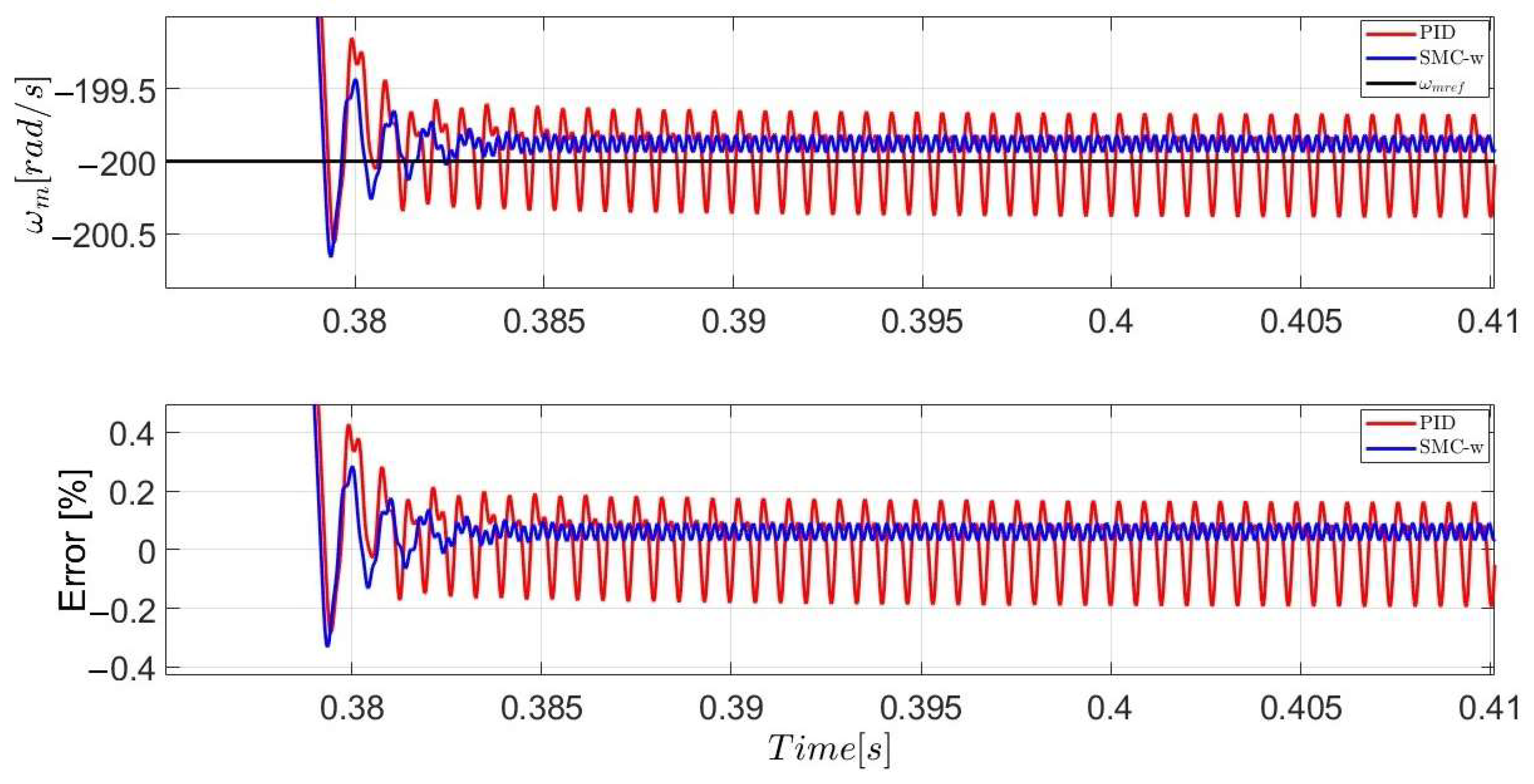
At t = 0.33 s, the reference speed changes from 200 to −200 rad/s (again, there is a change in the rotation of the motor). For this reference, a settling time of 0.056 s is presented for SMC-w and 0.078 s for the PID control. The maximum overshoot is 0.33% for the SMC-w and 0.285% for the PID control (see
Figure 13). The maximum error percentage is −0.33% for the SMC-w (which coincides with the maximum overshoot) and 0.42% for the PID control. The steady-state error (absolute value) is less than 0.1% for the SMC -w and less than 0.2% for the PID control.
Table 4 shows the performance of the two controls tested in this research. These results show that the longest settling time for the SMC-w is 0.0759 s and 0.0904 s for the PID, both when
changes from 200 to 400 rad/s. The steady-state error is less than 0.12% for the SMC-w and less than 0.34% for the PID control. This indicates that the SMC-w is more efficient than the PID control during the steady-state operation.
Figure 14a presents the output of the SMC-w and PID control for a speed reference of 200 rad/s and
Figure 14b for a 400 rad/s. For different speed references, the switching frequency is higher for the SMC-w than the PID and leads to a lower steady-state error. The switching frequency for both controllers is variable due to the saturation of the duty cycle.
The duty cycle saturates for both SMC-w and PID controllers. The duty cycle indicates the time percentage that the switch is ON over a certain period, so that it is constrained to the range 0–100% according to the power electronics definition. This time percentage is limited to 100% when its original value is higher, and it is limited to zero when it is lower. However, there are no values in the range (0–100%) in the PID controlled system because the values of the unsaturated controller output are overlarge, at around .
The design of both controllers assumes that the duty cycles are in the range [0, 1] with a fixed switching frequency most of the time. However, the switching frequency of the PID is not fixed in some moments due to the operation conditions, the PID parameters, and the duty cycle saturation.
Experimental and simulation applications of the PID controller to power converter are presented in [
21,
22].
Figure 15 shows the
,
, and
outputs for a speed reference of 200 rad/s. The result shows that the voltage in the inverter is higher than 40.086 V due to the interaction of the MOSFETs with the
filter. Furthermore, the switching frequency of the
is higher for the SMC-w, leading to less ripple in
and
, and a lower steady-state error. This phenomenon is expected because of the LC filter.
A high voltage in the motor input is presented because the coil magnetizes, and the capacitor charges and discharges during the transient state operation, leading to very short-time transient voltages higher than the power supply (40.086 Volts). Nevertheless, these high voltage values do not damage the motor as they are very short-time events. With the PID control, the transient voltage values are higher than those presented with the SMC-w, and this controller has a higher regulation error.
3.2. Duty Cycle Analysis
Figure 16 shows the evolution of the duty cycle as a function of the changes in the reference
, and also the evolution of the error. In the upper part of the figure, the SMC-w (in blue) and the PID control (in red) overlap due to the scale used to represent all the events. Duty cycles are held at a single value (0 or 1) when the steady-state operation has not been reached. Each duty cycle repeatedly changes between 0 and 1, and
is the inverse of
.
The error shows that the SMC-w (in blue) and PID (in red) overlap because of the scale that helps represent all the events tested. These results show the relationship between duty cycle and error: (i) during transient behavior of , is one when the speed error () is negative because the controller generates positive voltage, thus increasing the speed; (ii) in steady-state operation, the controller generates changing in order to obtain zero tracking error.
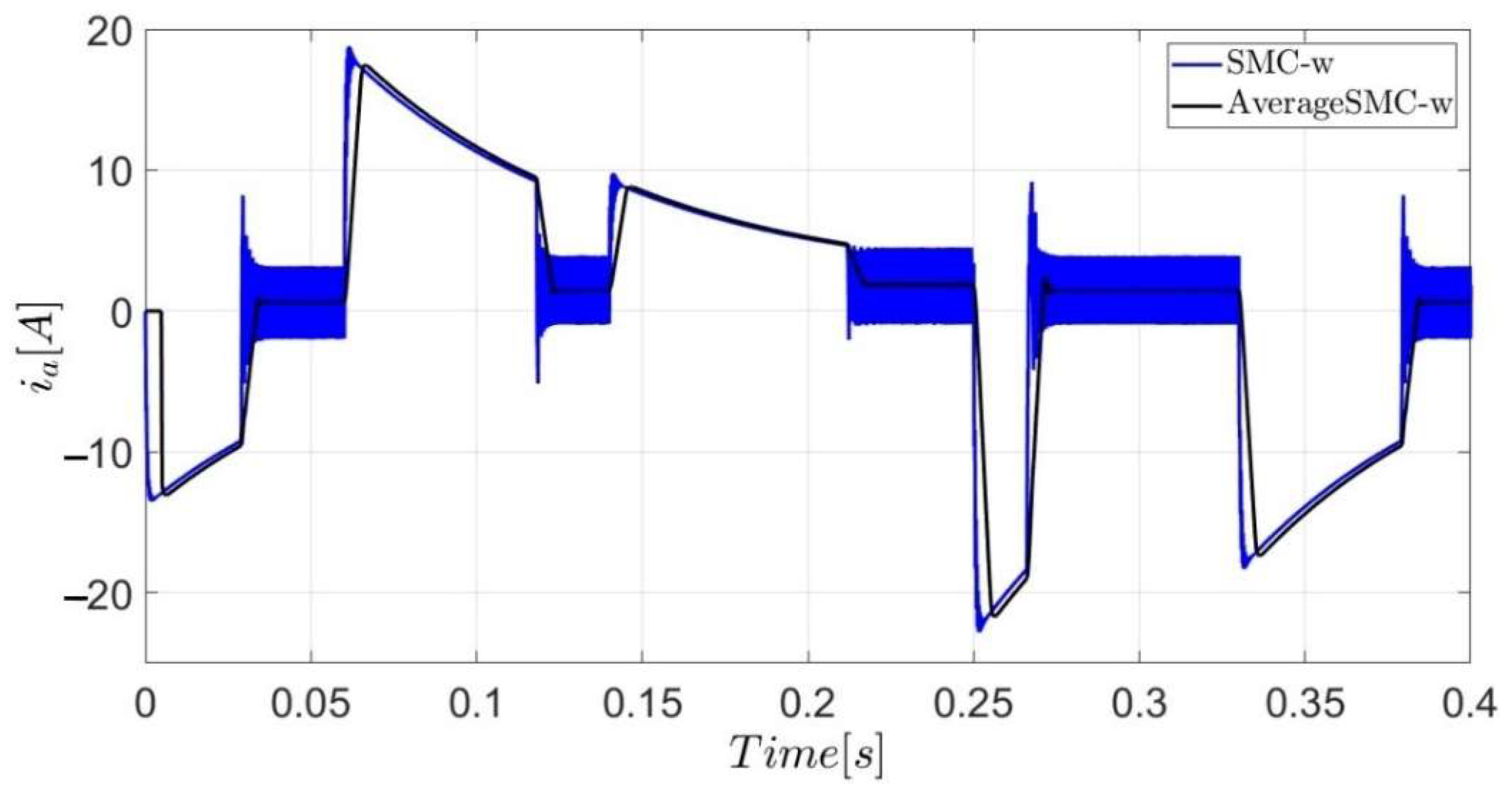
The behaviors of the speed, the error, and the current
are shown in
Figure 17. Figures related to the speed
and the percentage error show that the responses of the SMC-w (in blue) and PID (in red) overlap due to the scale at which they are being represented. When the reference
is modified, the following was observed: (i) during transient behavior, when
is negative, the motor exhibits negative current; (ii) in the steady-state operation of
, the current
oscillates around zero with a positive average value for all values of
, and the average value is higher for high
values, as shown in
Figure 18; (iii) the current
is more related to
than to
.
In this case, the current can reach higher values than the nominal to represent the complete dynamic behavior of the system; then, no overcurrent protection and current control were considered to avoid limiting the event. Therefore, the control effort is observed when seeking to reach the reference signal quickly. However, in the experimental test this is not presented due to the power source limitations and motor protection.
3.3. Effect of Load Torque Changes
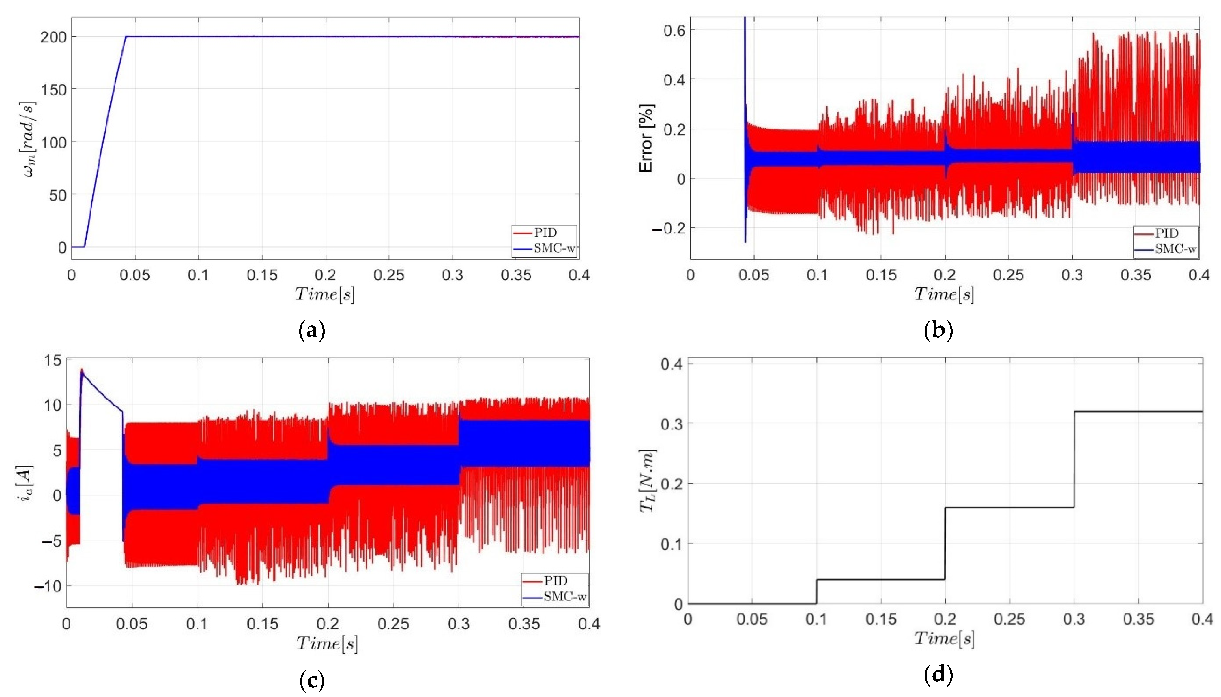
Figure 19 shows the behavior of the controlled system under load torque variations
, including the speed (
Figure 19a), the error (
Figure 19b), the current
(
Figure 19c), the torque (
Figure 19d), duty cycle (
Figure 19e), and voltage (
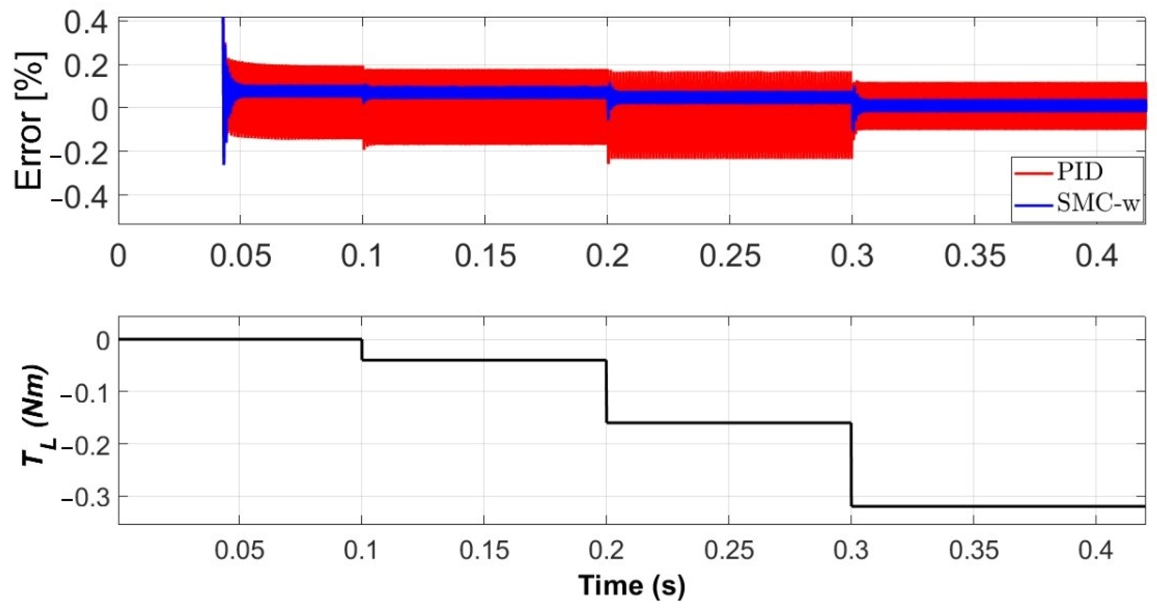
Figure 19f). The load torque remains at 0 N·m from 0 to 0.1 s; changes to 0.04 N·m from 0.1 to 0.2 s; then it moves to 0.16 N·m from 0.2 to 0.3 s; and finally changes to 0.32 N·m from 0.3 to 0.39 s, as shown in
Figure 19d.
The controlled variable
is shown in
Figure 19a and
Figure 20a, it is evident that the effect of the changes in the load torque was small in the controlled variable
, which shows that the control effectively maintains the output speed at its reference value. In addition, with the SMC-w, a maximum overshoot of 0.27% occurs when
changes from 0.16 N·m to 0.32 N·m. On the other side, with the PID control is difficult to identify the overshoot due to the repeated presence of oscillations.
The maximum steady-state tracking error (in percent) under load torque variations was less than 0.15% for the SMC-w and less than 0.6% for the PID control (
Figure 19b and
Figure 20b). This indicates that both control systems are effective in maintaining the output at its reference value (there are no large variations in the output speed) despite changes in
. However, the SMC-w has better regulation performance than the PID control, presenting a lower steady-state error. Furthermore, it is observed that: (i) there is an increase in the steady-state error for the applied torque change at t = 0.3 s, increased more than double the value in the previous time; (ii) the steady-state error does not present significant changes in response to the previous torque changes (0.04 N·m from 0.1 s to 0.2 s; 0.16 N·m from 0.2 to 0.3 s).
From
Table 5, the highest overshoot for the SMC-w and the highest steady-state errors for both the SMC-W and PID control occur when
changes from 0.16 Nm to 0.32 Nm. This value corresponds to the highest
considered for the study cases. In terms of the steady-state operation, the response of the SMC-w presents a lower percentage error than the PID control in all the study cases in which load torque variations were made.
The maximum overshoot values for the PID control when the load torque changes (0.04, 0.16, and 0.32 Nm) are not clear due to oscillations. Regarding the current
, it increases when the load torque requirements increase (
Figure 19c). In addition,
presents lower variations compared to those shown with the PID control.
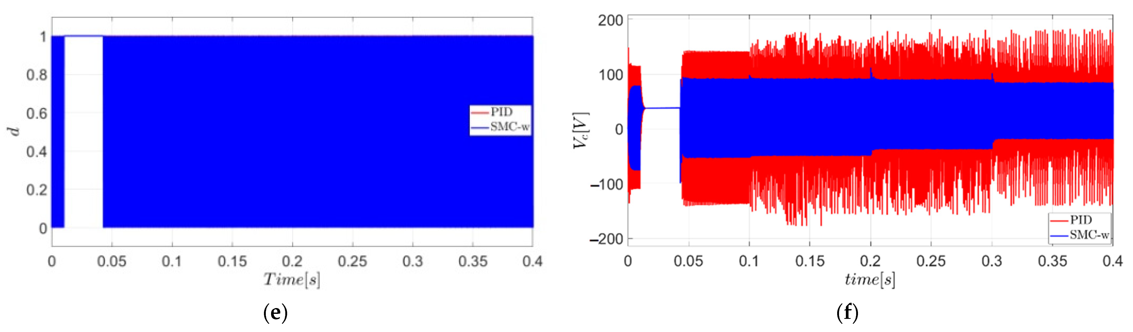
Figure 21a details the behavior of the duty cycle. When there is a variation in the load torque from 0.16 to 0.32 Nm at t = 0.3 s (
Figure 21b), the selection of this change corresponds to the time interval where the greater load torque is applied. It is evident that by increasing the value of the load torque, the control system compensates for variation by increasing the starting time of the duty cycle
, while
is the inverse of
. In addition, no other type of behavior is observed in the simulation.
Figure 19f shows the variation of the input voltage of the DC motor. It is observed that
is more stable and of lower value with a lower overshoot for the SMC-w than that generated with the PID, which is much larger and can affect the proper operation of the DC motor.
3.4. Contrast of Results Reported in the Literature
The performance of the SMC-w control system with a full-bridge inverter is compared with the carried out in [
19]. This work uses a buck converter with ZAD for speed control in a permanent magnet DC motor. The second case study discussed in the article was reproduced to establish a reference point for the analysis as accurately as possible. The behavior of the control system is studied under variations in the load torque (
Figure 22d).
The SMC-w system follows the reference (
= 200 rad/s) despite changes in
(
Figure 22a) and with a lower overshoot than that reported in the reference. In [
19], the tracking error percentage between
and the reference
is less than 2%, while the obtained in this paper is less than 0.3% (
Figure 22b). These values allow establishing that the SMC-w control technique is efficient in terms of the behavior of the control variable. However, the configuration of the full-bridge inverters with SMC-w presents significant variations in the voltage that feeds the DC motor (
Figure 22c). In addition, the internal resistances of the components were not considered, which could affect the results. This situation constitutes one of the approaches to be treated for further research that applies the SMC-w control with full-bridge inverters for the speed control of permanent magnet DC motors in real environments.
Figure 23 shows the speed and error when a variable speed reference is performed. The results show that for a negative reference, the regulation error is greater in the PID control than those values obtained when considering positive references. The error with the SMC-w remains approximately the same for both positive and negative references, and the steady-state error is lower than those obtained with the PID. In all cases, the percentage error in steady-state operation is always less than 8%, and for the zero reference, the value is very large due to division by zero.
The qualitative shape of the transient response of
and
with respect to
changes are symmetric for the SMC-w controller (see
Figure 8 and
Figure 23 for
, and
Figure 17 for
). However, the overshoot is lower, and the convergence time and the steady-state error are higher when
changes from −200 to 200 rad/s, than those values obtained when
changes from 200 to −200 rad/s (
Table 4 and
Figure 10 and
Figure 13). In contrast, for the PID controller, the steady-state error is significantly lower for
rad/s compared to −10 rad/s, see
Figure 23.
The PID steady-state error is higher when the
signal experiences a step change towards a lower value compared to the case of step changes towards a higher value (see
Figure 24). It is worth noticing that the difference between speed values of contrary signs is the clockwise and anticlockwise rotation direction.
The different duty cycles between the SMC-w and PID control systems lead to different voltage behavior at the motor input. For instance, for a
value of −200 rad/s, the controlled systems exhibit a similar behavior before the second oscillation, but the amplitude and frequency of oscillation are different afterward due to the difference in the control laws. Also, there are several overshoots in the transient voltage and an amplitude of 300% of the input value
for the PID control case, associated with the fact that the duty cycle remains at one for too long (see
Figure 25).
Figure 26 shows the motor speed and
Figure 27 shows the speed error for a positive speed reference and a load torque (
) less than and equal to zero; i.e., the load tries to accelerate the motor. The results show that the two controllers maintain the speed at the desired value with low steady-state errors (
Figure 26). Furthermore,
Figure 27 shows that for all values of
, the error is always lower for the SMC-w than the presented with the PID. Moreover, when the negative torque is greater, the error of the SMC-w is lower (
Figure 27).
4. Conclusions
In this work, the SMC-w technique was applied to a full-bridge inverter in order to regulate the speed of a permanent magnet DC motor. The simulation results showed that the controller achieves effective performance in speed tracking under variations in the reference signal and after disturbances in the load torque. The SMC-w exhibits a better performance during the steady-state operation as it reduces the error between 50 to 60% compared to the PID control. The full-bridge inverter with SMC-w presents a settling time and a maximum overshoot lower than the reported in the literature. However, the DC motor input voltage varies significantly during steady-state operation. When the reference signal changes, the control with the full-bridge inverters presents a faster settling time than other configurations in which a classic buck converter is used. This feature is because the system has reverse power, quickly reaching the lower values. Some robust control strategies are proposed in the literature for responding to disturbances and uncertainties, parametric variations, and non-linearities, adding complex control rules and considerable computational efforts. The SMC-w control technique has potential for industrial application as it allows achieving control objectives effectively, with low computational cost and a simple design, which benefits its implementation in practical environments.
Although strategies and recommendations are proposed for choosing the control parameters with SMC-w, its tuning can be optimized through evolutionary algorithms. Furthermore, a system stability analysis through bifurcations can also contribute to the choice of controller parameters. The combination of heuristic strategies with bifurcation analysis for the optimal tuning of the SMC-w controller parameters can provide regions of convergence towards optimal solutions with a reasonable computational cost for practical applications.
The qualitative shape of the transient response of the speed and current with respect to changes in the reference speed is symmetric for the SMC-w controller. However, the overshoot is lower, the convergence time is higher, and the steady-state error is higher for reference changes from −200 to 200 rad/s compared to 200 to −200 rad/s change. In contrast, for the PID control, the steady-state error of the speed is significantly lower for reference of 10 rad/s compared to −10 rad/s.


