Article

Adaptive Sliding Mode Attitude Control of Quadrotor UAVs Based on the Delta Operator Framework

CICAEET, School of Automation, Nanjing University of Information Science and Technology, Nanjing 210044, China
*
Author to whom correspondence should be addressed.
Symmetry 2022, 14(3), 498; https://doi.org/10.3390/sym14030498
Submission received: 27 January 2022 / Revised: 23 February 2022 / Accepted: 25 February 2022 / Published: 28 February 2022
(This article belongs to the Topic Dynamical Systems: Theory and Applications)

Abstract

:
In this paper, a novel adaptive sliding-mode control algorithm is proposed for the attitude control of quadrotor unmanned aerial vehicles (UAVs) under the delta operator framework. First, the delta operator technique is used to discretize the attitude control systems of a quadrotor UAV. Then, based on the linear matrix inequality technique, a linear sliding surface is designed to ensure the asymptotical stability of the quadrotor UAV attitude control system during the sliding motion process. Second, by the estimated external disturbance using a radical basis function (RBF) neural network, an adaptive sliding-mode attitude controller is designed such that the states of the quadrotor UAV attitude systems can be driven towards the desired sliding surface, and thus the attitude control objective of the qudarotor UAV is achieved. Compared with the traditional adaptive sliding-mode control algorithm, the proposed adaptive sliding-mode control algorithm can effectively realize the attitude control of a quadrotor UAV subject to strong disturbances and couplings. Finally, comparisons of the simulation results verify the effectiveness and superiority of the control algorithm proposed in this paper.

1. Introduction

Quadrotor unmanned aerial vehicles (UAVs) are multi-rotor aircraft that can take off, land and hover freely. Due to the high flexibility, low cost and strong concealment, they are widely used in various fields, such as rescue and disaster relief, aerial photography mapping, agricultural plant protection, inspection etc. A quadrotor UAV is a typical multi-input multi-output, under-actuated and strongly coupled nonlinear system. In the process of flight, attitude transformation and flight stability are the top priorities; therefore, it is particularly important to study the flight attitude control [1]. The research on the flight control of quadrotor UAVs has become a hotspot in recent years.
Currently, all kinds of control methods, including proportional-integral-differential (PID) control [2], active disturbance rejection control [3,4], sliding mode control [5,6,7,8] and neural network control [9], have been utilized in the attitude control of quadrotor UAVs. The article [2] shows the property of stability and robustness for a nonlinear implicit PID control algorithm of finite-time stabilization of quadrotor UAVs subject to constraints bounded external disturbance. Active disturbance rejection control comes from the improvement of PID control [3].
This is mainly composed of a tracking differentiator, state observer and nonlinear state error feedback control law. In [4], by the combination of adaptive control technique, a linear active disturbance rejection control strategy was developed to address the attitude control problem for the quadrotor UAV systems. Sliding mode control, as a well-known robust control method [5,6], has also been used in quadrotor flight control.
For instance, in [7], a discrete-time sliding-mode control algorithm was proposed for solving the position and attitude tracking control of a small quadrotor UAV. In [8], a sliding-mode attitude tracking control of the quadrotor UAVs with time-varying mass was designed. As an advanced intelligent control algorithm, an RBF neural network has a powerful learning ability, can learn complex uncertain models online and can deal with highly nonlinear control problems. The authors of [9] proposed a fault-tolerant control algorithm for quadrotors, which effectively enhanced the robustness of the system by combining the advantages of non-singular terminal sliding mode control and neural network.
To make full use of the advantages of sliding mode control and adaptive control methods, adaptive sliding mode control design of the quadrotor have also been investigated to improve robustness and adaptability in the literature. In [10], on the basis of Udwadia–Kalaba theory, the adaptive robust tracking control problem is considered for quadrotor UAVs with mismatched uncertainties.
In [11,12], adaptive fuzzy global sliding mode control methods are presented for quandrotor UAVs subject to parameter uncertainties and control chattering problems. A finite-time adaptive integral backstepping sliding mode control design method is introduced in [13], where adaptive control is used to compensate the unknown disturbance upper bound, and semi-global practical stability of the fight attitude control of the quadrotor is achieved.
It is worth noting that most of the results on adaptive sliding mode control of the quadrotor are based on the continuous-time controller, and the controller structure is relative complex. In fact, it was said in [14] that a discrete-time control scheme is much more suitable in practicable situations since the utilization of computer and network in the quadrotor, which is a challenging task has not been well solved so far.
On the other hand, signal discrete sampling in modern control theory is essential due to the wide application of digital controllers. Middleton and Goodwin introduced the delta operator discretization method to the modern control fields [15,16]. Compared with the discretization technique based on traditional shift operator method, the delta operator method is more suitable for high-speed sampling [17,18]. The authors in [19] studied the robust fault-tolerant stabilization of uncertain switched systems under delta operator framework.
In [20,21], the insensitive robust output tracking controller design and H filter design for discrete-time systems were studied in a unified delta operator approach framework. The results showed that the delta-domain model was better than the standard shift-domain model in avoiding the inherent numerical ill-conditions at high sampling rates. Recently, using the delta operator approach, the consensus problem of muli-agent systems are well investigated in [22,23]. It is worth noticing that few results have been published associated with the control design of quadrotor UAVs under a delta operator framework, which is a high-speed discrete sampling system.
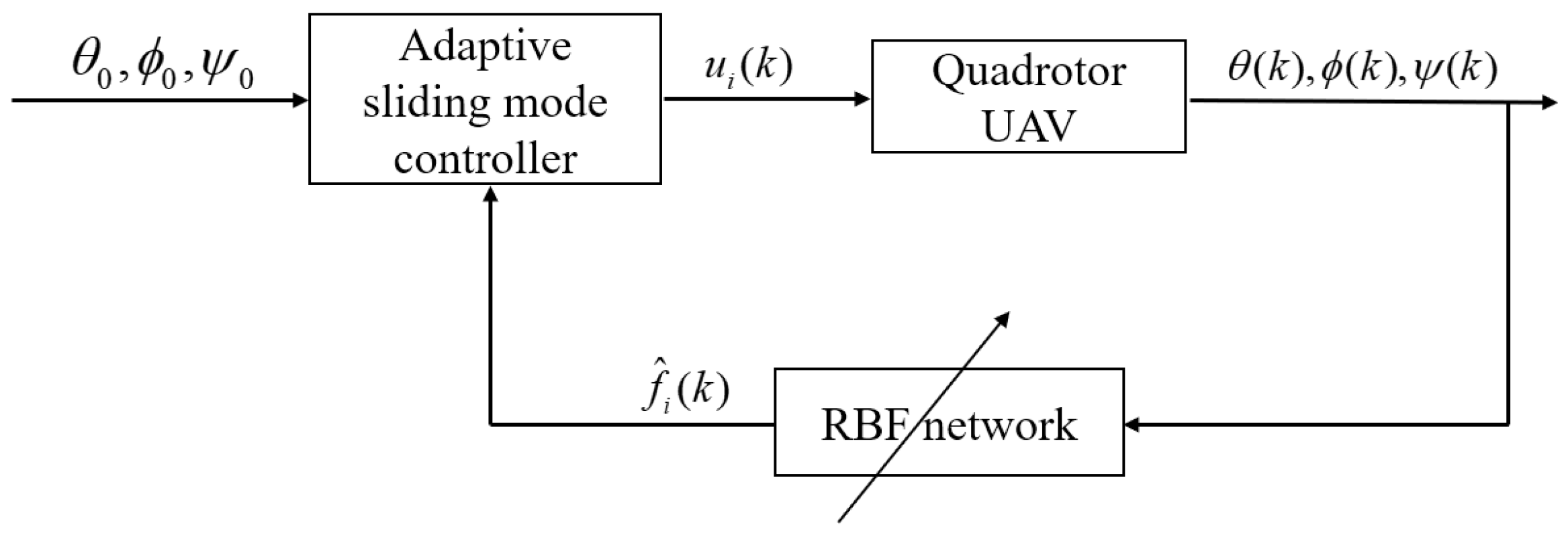
Inspired by the above research works, this paper is concerned with adaptive sliding-mode attitude control design problem for quadrotor UAVs based on delta operator framework. The main contribution of this paper is summarized as follows. First, the delta operator technique is used to discretize the attitude system of the quadrotor UAV. Then, the designs of linear sliding surface and an adaptive sliding mode reaching control law are shown in the delta domain. The design of the linear sliding surface is on the basis of linear matrix inequality technique, and it ensures the asymptotic stability of the quadrotor UAVs on sliding motion.
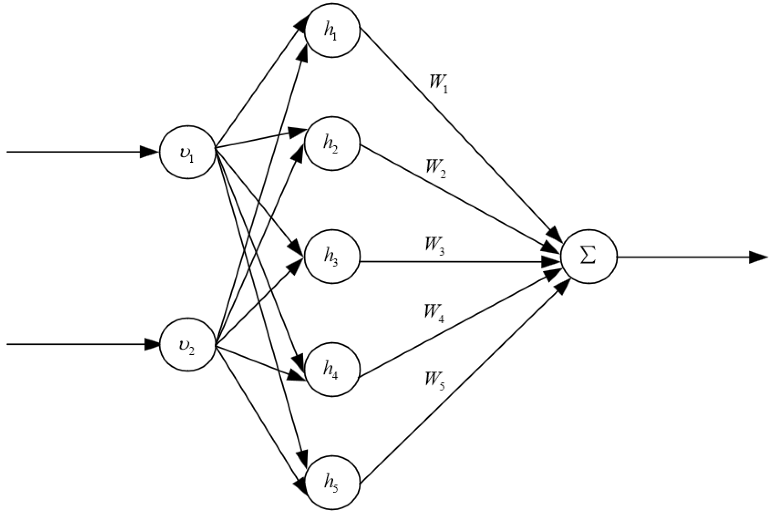
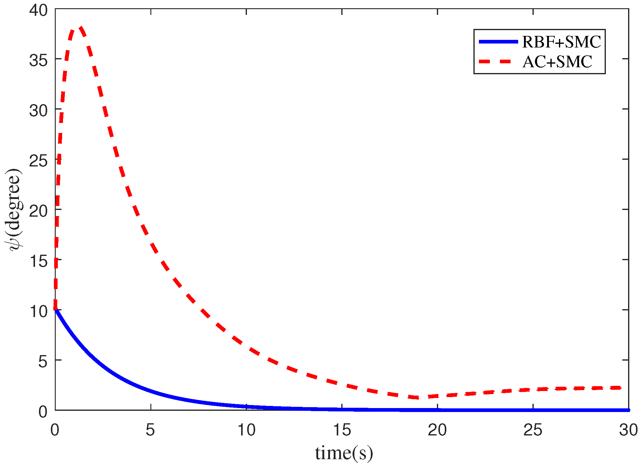
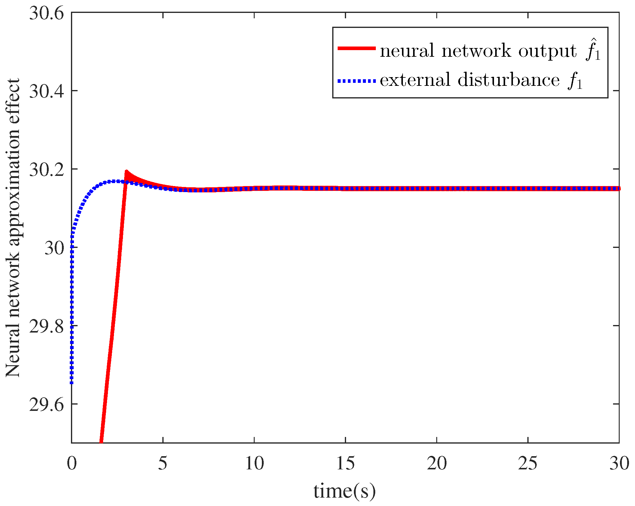
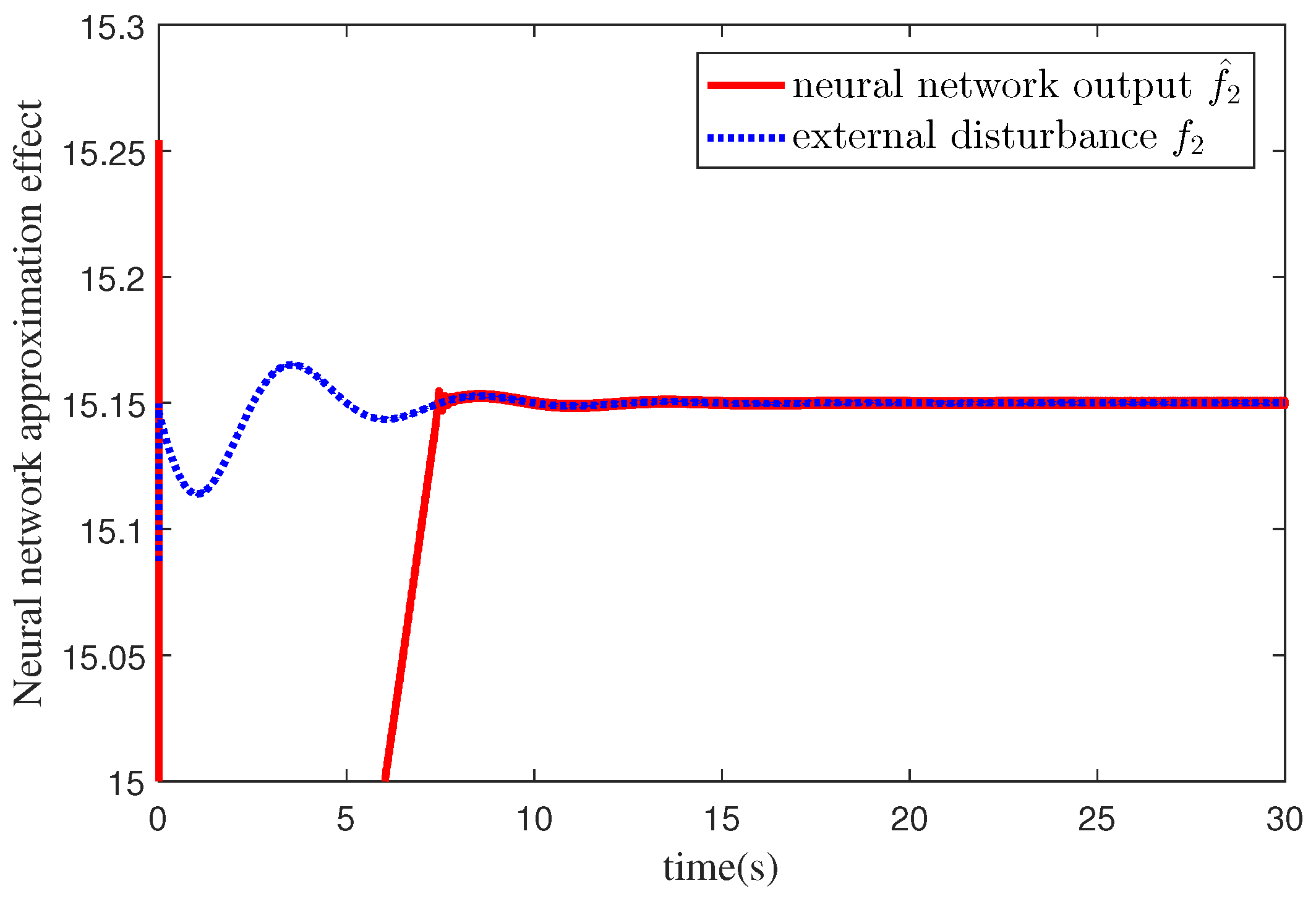
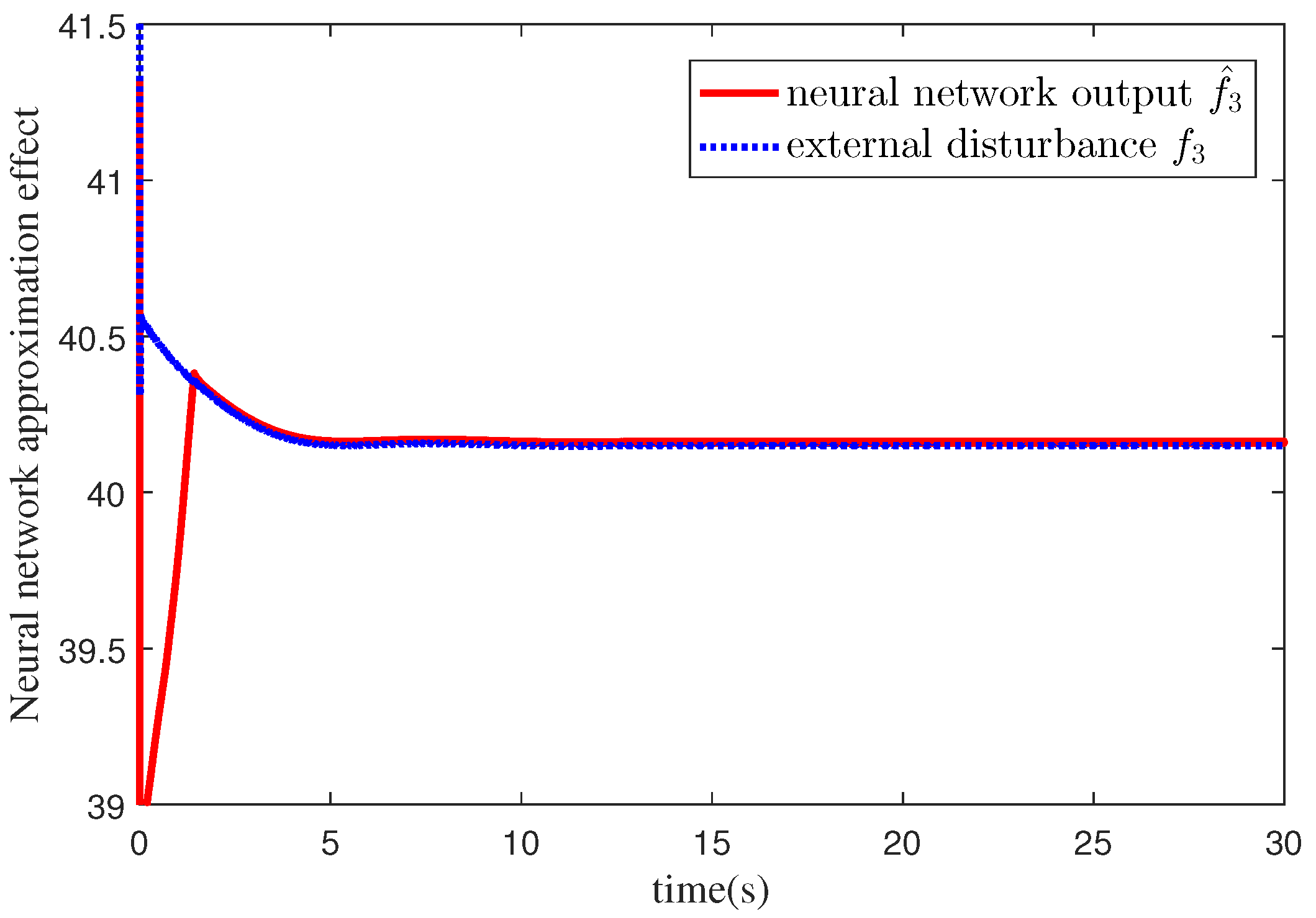
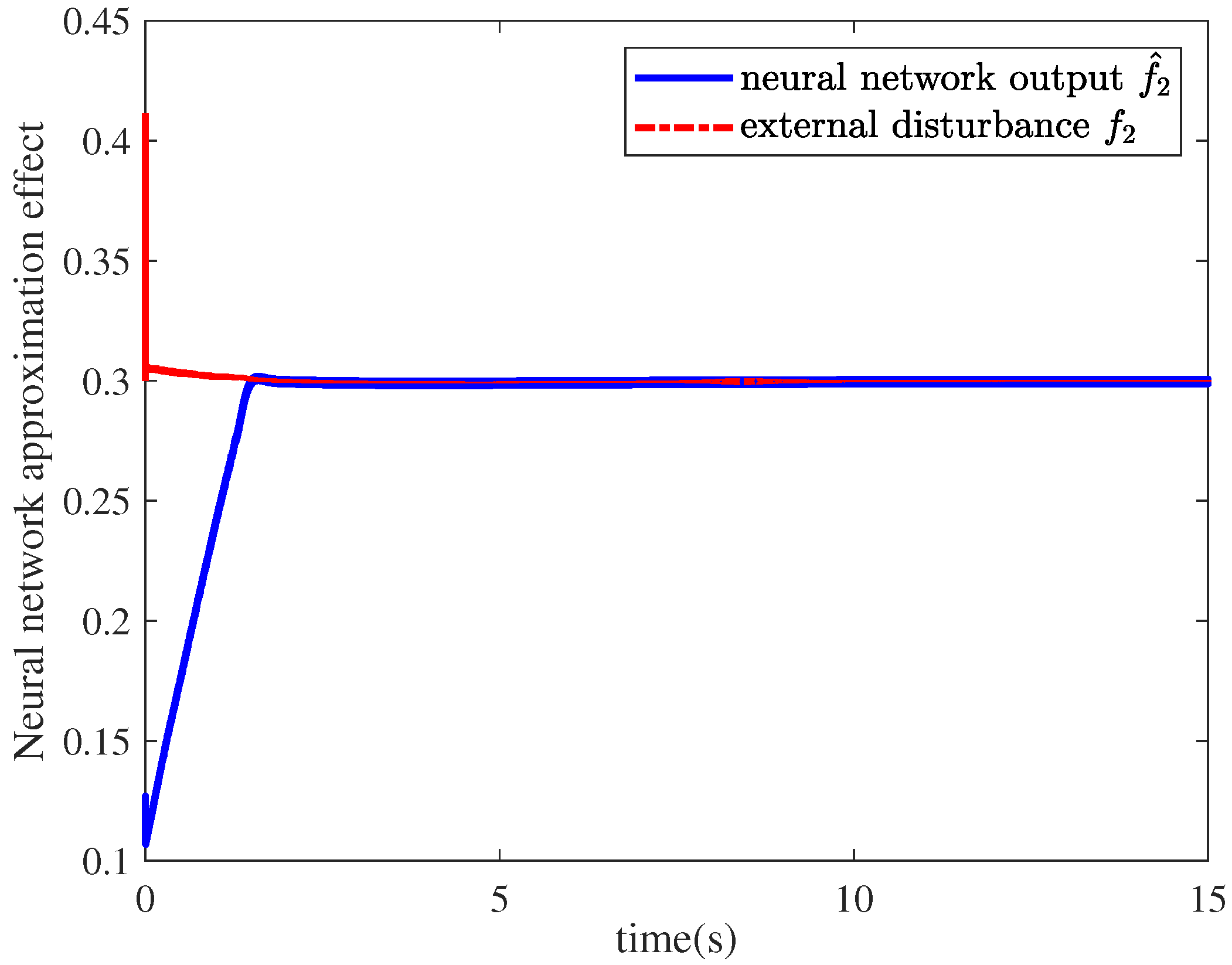
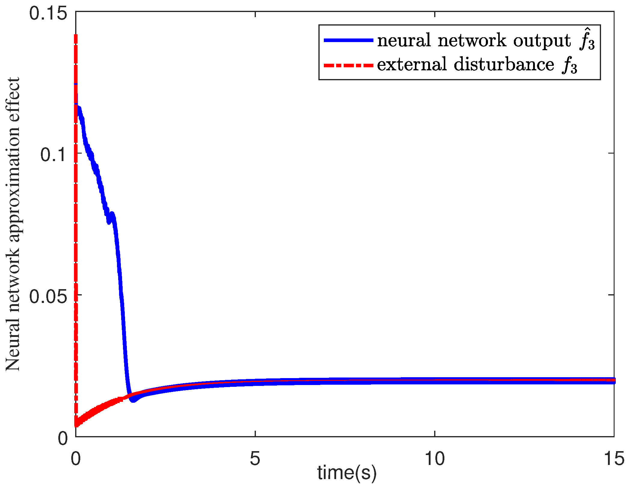
By the estimated external disturbance using radial basis function (RBF) neural network, the adaptive sliding mode controller is designed for ensuring all attitudes of the quadrotor UAVs can be driven to the proposed sliding surface and thus the attitude control is achieved. Finally, simulation result comparisons demonstrate the effectiveness and superiority of the proposed attitude control algorithm.
The remainder of this paper is organized as follows. In Section 2, a system model of quadrotor UAVs is presented. In Section 3, a sliding-mode attitude control design algorithm is presented, which includes the design of a sliding surface and the design of an adaptive sliding mode controller. In Section 4, an illustrative simulation example is provided to demonstrate the effectiveness and superiority of the proposed method. Our conclusions are given in Section 5.

2. System Model Description of Quadrotor UAV

The quadrotor UAV has a simple appearance and can take off and land vertically with high control flexibility. It consists of four electrical motors with propellers, which are attached to a rigid cross frame. Supposing the quadrotor UAV has a symmetrical structure, the drag and the thrust forces are proportional to the square of the rotors speed, and ignoring blade flapping and gyro effect, the linearized quadrotor UAV model is obtained from [24,25,26]:
J 1 ϕ ¨ ( t ) = K 1 l ϕ ˙ ( t ) + l u 1 ( t ) + f 1 ( t ) , J 2 θ ¨ ( t ) = K 2 l θ ˙ ( t ) + l u 2 ( t ) + f 2 ( t ) , J 3 ψ ¨ ( t ) = K 3 ψ ˙ ( t ) + c u 3 ( t ) + f 3 ( t ) ,
where ϕ ( t ) , θ ( t ) and ψ ( t ) are the roll angle, pitch angle and yaw angle of the quadrotor UAV, respectively. J 1 , J 2 and J 3 represent the moments of inertia of each axis of the UAV, K 1 , K 2 and K 3 are the drag coefficients and are positive constants, l represents the distance from the center of each rotor to the center of the body, c is the proportional coefficient of force and torqu, u i ( t ) represent the control input to the quadrotor UAVs with u 1 ( t ) = F 1 ( t ) F 2 ( t ) F 3 ( t ) + F 4 ( t ) , u 2 ( t ) = F 1 ( t ) + F 2 ( t ) F 3 ( t ) F 4 ( t ) and u 3 ( t ) = F 1 ( t ) F 2 ( t ) + F 3 ( t ) F 4 ( t ) , F i ( t ) represents the lift of propeller. In addition, f 1 ( t ) , f 2 ( t ) and f 3 ( t ) represent unknown external disturbances and coupling terms.
Remark 1.
If the unknown external disturbances and couplings are ignored, the attitude control model of the quadrotor UAVs can be described as follows.
J 1 ϕ ¨ ( t ) = K 1 l ϕ ˙ ( t ) + l u 1 ( t ) , J 2 θ ¨ ( t ) = K 2 l θ ˙ ( t ) + l u 2 ( t ) , J 3 ψ ¨ ( t ) = K 3 ψ ˙ ( t ) + c u 3 ( t ) ,
Research works based on model (2) can be seen in [27,28,29,30,31]. Clearly, the dynamic model (1) in this paper is more suitable in practical situations than (2).
Let x 1 ( t ) = ϕ ( t ) ϕ ˙ ( t ) , x 2 ( t ) = θ ( t ) θ ˙ ( t ) , x 3 ( t ) = ψ ( t ) ψ ˙ ( t ) , A ¯ 1 = 0 1 0 K 1 l J 1 , A ¯ 2 = 0 1 0 K 2 l J 2 , A ¯ 3 = 0 1 0 K 3 J 3 , B ¯ 1 = 0 l J 1 , B ¯ 2 = 0 l J 2 and B ¯ 3 = 0 c J 3 , the linearized quadrotor UAVs can be rewritten as
x ˙ i ( t ) = A ¯ i x i ( t ) + B ¯ i u i ( t ) + B ¯ i f i ( t ) ,
where i = 1 , 2 , 3 , x i ( t ) R 2 is the state variable of the ith attitude control system, A ¯ i R 2 × 2 and B ¯ i R 2 × 1 are the system matrix and control input matrix, respectively.
Applying the delta operator technique to discretize the system (3), one can find the quadrotor UAVs in the delta domain
δ x i ( t k ) = A i x i ( t k ) + B i u i ( t k ) + B i f i ( t k ) ,
where δ x i ( t k ) is the delta operator calculation for the state variable x i ( t k ) . It is defined mathematically as
δ x i t k = d d t x i ( t ) , T = 0 , x i ( t k + T ) x i ( t k ) T , T 0 ,
where t k = k T , T is the sampling period. Clearly, when T 0 , the delta operator δ x i ( t k ) is a derivative operation x ˙ ( t ) and can be used to describe a continuous time dynamic system. When T = 1 , the delta operator δ x i ( t k ) is a difference operation of traditional shift operator, which can be used to describe a traditional discrete time dynamical system. In terms of the definition of the delta operator, one can see that A i = ( e A ¯ i T I ) / T , B i = ( 0 T e A ¯ i T B ¯ i d t ) / T , i = 1 , 2 , 3 .
For the control design of the quadrotor UAVs 4 under the delta operator framework, it is assumed that the pair ( A i , B i ) is controllable and that column B i is full rank, i = 1 , 2 , 3 .
To facilitate the proof, the relevant lemmas are introduced. Lemma 1 shows the definition of the asymptotical stability in the delta domain, Lemma 2 and Lemma 3 will be used to the theoretical proof of Theorem 1, where Lemma 2 is used to the mathematical calculation of delta operator, and Lemma 3 is used as a technique to convert a nonlinear linear matrix inequality into a linear matrix inequality.
Lemma 1
([32]). For the delta operator system
δ ( x ( t k ) ) = g ( x ( t k ) ) ,
where g ( x ( t k ) ) with g ( 0 ) = 0 , is a linear or nonlinear function, if there exists a positive definite function V ( x ( t k ) ) in the delta domain, such that for any state x ( t k ) satisfies
δ V ( x ( t k ) ) = V ( x ( t k + T ) ) V ( x ( t k ) ) T < 0 ,
then the system (6) is asymptotical stable in the delta domain.
Lemma 2
([16]). (Differentiation of Product). For any time functions x ( t k ) and y ( t k ) , we have the following fact.
δ x ( t k ) y ( t k ) = ( δ x ( t k ) ) y ( t k ) + x ( t k ) ( δ y ( t k ) ) + T δ x ( t k ) δ y ( t k ) .
Lemma 3
([33]). (Schur–Complement Lemma) For a given symmetric matrix S = S 11 S 12 S 21 S 22 , where S 11 = S 11 T , S 22 = S 22 T , S 12 = S 21 T , the inequalities (9)–(11) are equivalent to each other,
S < 0 ,
S 11 < 0 , S 22 S 21 S 11 1 S 12 < 0 ,
S 22 < 0 , S 11 S 12 S 22 1 S 21 < 0 .

3. Design of the Sliding Mode Attitude Control Algorithm

The design of the sliding-mode attitude control algorithm of the quadrotor UAVs is divided into two steps. The first step is to design a linear sliding surface σ i ( k ) = 0 to ensure the stability of the quadrotor UAVs during sliding motion process. The second step is to design an adaptive sliding mode attitude controller such that all attitudes of the quadrotor UAVs can be driven to the designed sliding surface σ i ( k ) = 0 .

3.1. Sliding Surface Design

Let x i ( t k ) = x i 1 ( t k ) x i 2 ( t k ) , A i = A i 11 A i 12 A i 21 A i 22 and B i = 0 B i 2 , the quadrotor UAV (4) can be rewritten as:
δ x i 1 ( t k ) = A i 11 x i 1 ( t k ) + A i 12 x i 2 ( t k ) ,
δ x i 2 ( t k ) = A i 21 x i 1 ( t k ) + A i 22 x i 2 ( t k ) + B i 2 u i ( t k ) + B i 2 f i ( t k ) .
The linear sliding surface is designed as
σ i ( t k ) = S i x i ( t k ) = 0 ,
where i = 1 , 2 , 3 , S i = [ Z i 1 ] is the sliding vector with Z i R to be determined. Substituting σ i ( t k ) = Z i x i 1 ( t k ) + x i 2 ( t k ) into (12), the sliding dynamics, i.e., the reduced order quadrotor UAVs system δ x i 1 ( t k ) is described as
δ x i 1 ( t k ) = ( A i 11 A i 12 Z i ) x i 1 ( t k ) .
To make the sliding motion on (15) be asymptotical stable, it is necessary to design the appropriate parameter Z i of the sliding surface.
Theorem 1.
If there exist positive real parameters X i and W i and a real number Y i , such that the following linear matrix inequality
2 W i A i 11 X i A i 12 Y i T W i H e ( A i 11 X i A i 12 Y i ) 0 T X i < 0
is satisfied for a given sampling period T > 0 , then the reduced order quadrotor UAVs system (15) is asymptotical stable, where H e ( A i 11 X i A i 12 Y i ) = A i 11 X i A i 12 Y i + ( A i 11 X i A i 12 Y i ) T . The symbol ∗ is used to represent a term that is induced by symmetry. Furthermore, the sliding surface is designed as
σ i ( t k ) = [ Y i X i 1 1 ] x i ( t k ) = 0 .
Proof of Theorem 1. 
Let A i 1 = A i 11 A i 12 Z i , one can see that the sliding motion obeys δ x i 1 ( t k ) = A i 1 x i 1 ( t k ) . Now, the Lyapunov function candidated is chosen as
V 1 ( t k ) = x i 1 T ( t k ) P i x i 1 ( t k ) ,
where P i is a positive definite symmetric matrix.
In terms of Lemma 2, one has
δ V 1 ( t k ) = 2 x i 1 T ( t k ) P i δ x i 1 ( t k ) + T ( δ x i 1 ( t k ) ) T P i δ x i 1 ( t k ) .
Furthermore, let us introduce
0 = 2 ( δ x i 1 ( t k ) ) T W ^ i [ δ x i 1 ( t k ) A i 1 x i 1 ( t k ) ] ,
where W ^ i is a positive definite matrix, and by the combination of the sliding motion Equations (15) and (20), the state trajectory of (19) along the reduced-order system (15) becomes
δ V 1 ( t k ) = δ x i 1 ( t k ) x i 1 ( t k ) T Θ i δ x i 1 ( t k ) x i 1 ( t k ) ,
where
Θ i = T P i W ^ i W ^ i T W ^ i A i 1 P i A i 1 + A i 1 T P i .
It is clear that, when Θ i > 0 , the reduced-order system of the quadrotor UAV (15) is asymptotically stable by Lemma 1. Now, multiplying the left and right sides of Equation (22) with diag W ^ i 1 , P i 1 , we have
T W ^ i T P W ^ i 1 2 W ^ i 1 A i 1 P i 1 P i 1 A i 1 T + A i 1 P i 1 < 0 .
Using the Schure–Complement Lemma, one can obtain the condition (16) for asymptotically stable of the sliding motion, where X i = P i 1 , W i = W ^ i 1 , Y i = Z i X i . The proof of Theorem 1 is therefore completed. □

3.2. Adaptive Sliding Mode Controller Design

To design the adaptive sliding mode controller, a RBF neural network is first used online to approximate the unknown nonlinear external disturbance f i ( t k ) . The RBF neural network usually consists of three parts: Input layer, hidden layer and output layer. How to configure the RBF neural network has been well investigated in the existing works, please see [34] for details. In this paper, the RBF neural network with 2 5 1 structure is adopted and shown in Figure 1.
The input and output algorithm of a single RBF network is
h j ( υ ) = exp υ c j 2 2 b j 2 ,
f ( t k ) = ( W ) T h j ( υ ) + η ,
where υ is the input of the neural network, j is the jth node of the hidden layer, c j is the center vector of the hidden layer node, b j is the width vector of the hidden layer neurons, W is the network approximation ideal weight, η η max is the network approximation error.
For the attitude control system of quadrotor UAVs (4), the neural network input is taken as υ i = x i 1 ( t k ) x i 2 ( t k ) T , and the estimated output of the RBF neural network for the unknown nonlinear function f i ( t k ) is:
f i ( t k ) = W i T h i j ( υ i ) ,
where W i is the estimated weight of the network, i = 1 , 2 , 3 . The adaptive adjustment law of the estimated weight of the network is designed in the delta domain as follows.
δ W i ( t k ) = γ i σ i ( t k ) S i B i h i j ( υ i ) .
The designed adaptive sliding mode controller is shown as follows.
u i ( t k ) = ( S i B i ) 1 [ S i A i x i ( t k ) + S i B i f i ( t k ) + ε i sign ( σ i ( t k ) ) + β i σ i ( t k ) ] ,
where ε i and β i are adjustable positive parameters, i = 1 , 2 , 3 .
Theorem 2.
Considering the quadrotor UAVs (4) under the delta operator framework, the adaptive sliding-mode attitude controller is designed as shown in (27) and (28), all the attitudes of the quadrotor UAVs can be driven towards the designed sliding surface σ i ( t k ) = 0 shown in (14), and the asymptotical stablity is achieved.
Proof of Theorem 2. 
Take the Lyapunov function candidated in the delta domain as
V 2 ( t k ) = σ i T ( t k ) σ i ( t k ) 2 + 1 2 γ i W ˜ i T ( t k ) W ˜ i ( t k ) ,
where γ i > 0 is the network tuning parameter, and W ˜ i ( t k ) = W i W i , i = 1 , 2 , 3 . By Lemma 2, one can see that
δ V 2 ( t k ) = σ i ( t k ) δ σ i ( t k ) + 1 2 γ i ( δ W ˜ i ( t k ) ) T W ˜ i ( t k ) + 1 2 γ i W ˜ i T ( t k ) δ W ˜ i ( t k ) + T 2 ( δ σ i ( t k ) ) 2 + T 2 γ δ W ˜ i ( t k ) ) 2 = σ i ( t k ) δ σ i ( t k ) + 1 γ i W ˜ i T ( t k ) ( δ W i ( t k ) ) + i ( t k ) ,
where i ( t k ) = T 2 ( δ σ i ( t k ) ) 2 + T 2 γ i δ W ˜ i ( t k ) ) 2 , i = 1 , 2 , 3 .
On the other hand, noticing that
δ σ i ( t k ) = S i [ A i x i ( t k ) + B i u i ( t k ) + B i f i ( t k ) ] .
Substituting the designed adaptive sliding mode controller (28) into (31), one can further obtain
δ σ i ( t k ) = S i B i [ f i ( t k ) f i ( t k ) ] ε i sign ( σ i ( t k ) ) β i σ i ( t k ) .
Noticing, from (25) and (26), that f i ( t k ) f i ( t k ) = W ˜ i T ( t k ) h i j ( υ i ) + η i , i = 1 , 2 , 3 , In terms of (30) and (32), it is not difficult to see that
δ V 2 ( t k ) = σ i ( k ) S i B i [ W ˜ i T ( t k ) h i j ( υ i ) + η i ] β i σ i ( t k ) 2 ε i σ i ( t k ) s i g n ( σ i ( t k ) ) + 1 γ i W ˜ i T ( t k ) δ W i ( t k ) + i ( t k ) ( σ i ( k ) ( S i B i ) ) W ˜ i T ( t k ) h i j ( υ i ) + σ i ( t k ) S i B i η i ε i σ i ( t k ) β i σ i ( t k ) 2 + 1 γ i W ˜ i T ( t k ) δ W i ( t k ) + i ( t k ) W ˜ i T ( t k ) [ σ i ( t k ) ( S i B i ) h i j ( υ i ) + 1 γ i δ W i ( t k ) ] + σ i ( t k ) S i B i η i β i σ i ( t k ) 2 ε i σ i ( t k ) + i ( t k ) .
Substituting the adaptive law (27) into (33), one can see that
δ V 2 ( t k ) σ i ( t k ) S i B i η i ε i σ i ( t k ) β i σ i ( t k ) 2 + i ( t k ) .
Since i ( t k ) is reasonably bounded [18] and it is also small when the sampling period T is close to 0; then, as long as ε i and β i are large enough to satisfy ε i + β i σ i ( t k ) η i S i B i , it is easy to obtain δ V 2 ( t k ) < 0 . Therefore, under the action of the RBF neural-network-based adaptive law (27) and the sliding mode controller (28), the state of the quadrotor UAVs (4) can reach the designed sliding surface σ i ( t k ) = 0 , and asymptotical stability can be finally guaranteed. □
The diagram of the RBF neural-network-based adaptive sliding-mode control algorithm is shown in Figure 2, where the RBF network is used to estimate the unknown external disturbances and couplings. The adaptive sliding mode controller was designed to achieve the flight attitude control using the estimated information.

4. Illustrative Example

In this section, simulation results are shown to verified the effectiveness and superiority of the proposed adaptive sliding mode control design method of quadrotor UAVs. In Section 4.1, parameter settings and model of the quadrotor UAVs are given; and in Section 4.2, the design of the linear surfaces is shown. Simulation results are shown in Section 4.3.

4.1. Parameter Settings and Modelling of the Quadrotor UAV

To verify the effectiveness of adaptive sliding-mode attitude control algorithm for quadrotor UAVs proposed in this paper, simulation experiments were performed. The physical parameters of the quadrotor UAVs are shown in Table 1.
The continuous-time models of the roll angle, the pitch angle and the yaw angle are expressed as
ϕ ˙ ( t ) ϕ ¨ ( t ) = 0 1 0 0.724 ϕ ( t ) ϕ ˙ ( t ) + 0 4.789 u ( t ) + 0 4.789 f ( t ) .
θ ˙ ( t ) θ ¨ ( t ) = 0 1 0 0.724 θ ( t ) θ ˙ ( t ) + 0 4.789 u ( t ) + 0 4.789 f ( t ) .
ψ ˙ ( t ) ψ ¨ ( t ) = 0 1 0 1.364 ψ ( t ) ψ ˙ ( t ) + 0 4.789 u ( t ) + 0 4.789 f ( t ) .
Setting the sampling time T = 0.01 s and taking the state x 1 ( t ) = ϕ ( t ) ϕ ˙ ( t ) , now using the delta operator discretization technique in [16], the roll angle system model in the delta operator framework is established as follows.
δ x 1 ( t k ) = 0 0.9964 0 0.7214 x 1 ( t k ) + 0.0477 4.7545 u 1 ( t k ) + 0.0477 4.7545 f 1 ( t k ) .
Similarly, let x 2 ( t ) = θ ( t ) θ ˙ ( t ) and x 3 ( t ) = ψ ( t ) ψ ˙ ( t ) , one can also establish the pitch angle system model after the discretization of the delta operator
δ x 2 ( t k ) = 0 0.9964 0 0.7214 x 2 ( t k ) + 0.0477 4.7545 u 2 ( t k ) + 0.0477 4.7545 f 2 ( t k ) .
and the yaw angle system model after discretization of the delta operator
δ x 3 ( t k ) = 0 0.9932 0 1.3547 x 3 ( t k ) + 0.0476 4.7241 u 3 ( t k ) + 0.0476 4.7241 f 3 ( t k ) .

4.2. Design of Linear Surfaces

For the quadrotor UAVs (38)–(40), by solving the linear matrix inequality (16) with MATLAB LMI control toolbox, we can find X 1 = X 2 = X 3 = 1.0133 , Y 1 = Y 2 = 0.3357 and Y 3 = 0.3367 . From Z i = Y i X i 1 , the sliding vectors are S 1 = S 2 = 0.3313 1 and S 3 = 0.3323 1 . Thus, the sliding surfaces are designed as σ 1 ( t k ) = [ 0.3313 1 ] x 1 ( t k ) = 0 , σ 2 ( t k ) = [ 0.3313 1 ] x 2 ( t k ) = 0 and σ 3 ( t k ) = [ 0.3323 1 ] x 3 ( t k ) = 0 .

4.3. Simulation Retsults

For the dynamical model shown in (38)–(40), the effectiveness and superiority of the proposed control algorithm are verified via simulation comparisons. Comparison results of the traditional adaptive sliding-mode control algorithm (AC+SMC) in [25] and the proposed adaptive sliding-mode control algorithm (RBF+SMC) in this paper are given.
In [25], f i ( t k ) is supposed as f i ( t k ) η 1 + η 2 x i ( t k ) with η 1 and η 2 are unknown positive constants. Clearly, such an assumption is relatively strict, which requires not only linear growth conditions but also ignores the coupling problem. Applying the design method there, adaptive laws and controller used are designed as in (41)–(43).
δ η ^ i 1 ( t k ) = σ i ( t k ) S i B i ,
δ η ^ i 2 ( t k ) = σ i ( t k ) S i B i x i ( t k ) ,
u i ( t k ) = S i B i 1 [ S i A i x i ( t k ) + ( μ i + η ^ i 1 ( t k ) S i B i + η ^ i 2 ( t k ) S i B i x i ( t k ) ) sign ( σ i ( t k ) ) ] ,
where η ^ i 1 ( t k ) and η ^ i 2 ( t k ) represent the estimated values of unknown interference coefficients η i 1 and η i 2 , respectively.
Taking the initial value of the attitude angle of the quadrotor UAVs as ϕ θ ψ = 30 15 10 , the center vector of each RBF neural network is c j = [ 1 0.5 0   0.5 1 ] , the width vector is b j = 3 .
To show the effectiveness and superiority of the proposed method clearly. Two kinds of disturbances are considered. The first is taken as
f 1 ( t k ) = 0.15 + 0.1 sin ( 0.2 π t k ) 0 x 1 ( t k ) + 30 cos ( x 11 ( t k ) x 12 ( t k ) ) , f 2 ( t k ) = 0.15 + 0.2 sin ( 0.4 π t k ) 0 x 2 ( t k ) + 15 cos ( x 21 ( t k ) x 22 ( t k ) ) , f 3 ( t k ) = 0.15 + 0.4 sin ( 0.3 π t k ) 0 x 3 ( t k ) + 40 ( 1 x 31 ( t k ) x 32 ( t k ) ) .
The adaptive adjustment gain parameter μ i in [25] is taken as 0.5 during simulation. The parameters of the proposed adaptive sliding mode controller are shown in Table 2.
The simulation results of the attitude angle response results of the quadrotor UAVs under the action of the traditional adaptive sliding-mode control algorithm (AC+SMC) and the proposed adaptive sliding-mode control algorithm (RBF+SMC) proposed in this paper are shown in Figure 3, Figure 4 and Figure 5. It can be seen from Figure 3, Figure 4 and Figure 5 that the traditional adaptive sliding-mode control algorithm (AC+SMC) cannot ensure that the attitude angle of the UAVs converges to the origin, the curve of each attitude angle has a distinct mutation and oscillation, and the overshoot is large, which cannot realize the stable control of the attitude of the quadrotor UAV.
The approximation results of the external disturbances f 1 ( t k ) , f 2 ( t k ) and f 3 ( t k ) by the RBF neural network are shown in Figure 6, Figure 7 and Figure 8. It can be seen that the RBF neural-network-based adaptive scheme can estimate the unknown f i ( t k ) quickly and well. In addition, Table 3, shows the performance comparisons for steady-state time and Table 4 shows the approximation time of RBF neural network to f i ( t ) . Clearly, the quadrotor UAVs under proposed control offer a faster convergence speed.
To further illustrate the advantages of the proposed adaptive sliding mode control method, another kind of disturbances is taken as follows.
f 1 ( t k ) = 0.1 + x 22 ( t k ) x 32 ( t k ) + 0.02 x 22 ( t k ) , f 2 ( t k ) = 0.3 + x 12 ( t k ) x 32 ( t k ) + 0.03 x 12 ( t k ) , f 3 ( t k ) = 0.02 + x 12 ( t k ) x 22 ( t k ) .
One can see that the cross-coupling is considered here. Now, the design parameters of the traditional adaptive sliding mode control in [25] and the proposed adaptive sliding mode controller are shown in Table 5 and Table 6, respectively.
It can be seen from Figure 9, Figure 10 and Figure 11 that the traditional adaptive sliding-mode control algorithm (AC+SMC) cannot well ensure that the attitude angle of the UAVs converges to the origin. When there is a couplings problem, the curve of each attitude angle has a distinct mutation and oscillation, and the overshoot is large, i.e., it cannot realize the stable control of the attitude of the quadrotor UAV. At the same time, the flight attitude control can still estimate the unknown disturbance well (see Figure 12, Figure 13 and Figure 14) by the proposed design method in this paper (see Figure 9, Figure 10 and Figure 11). Table 7 also shows that the steady-state time of the proposed method is quicker for each attitude angle, and Table 8 shows that the adaptive RBF neural network can estimate f i ( t ) in a quick way.
It can be seen from the above statements that the proposed adaptive sliding-mode control algorithm in the delta operator framework can effectively compensate the unknown nonlinear disturbances and achieve better control performance simultaneously, which is more suitable for use in the flight attitude control of quadrotor UAVs. However, this is based on the assumption that the actuator does not encounter various faults. How to design a sliding mode fault-tolerant attitude controller is an interesting and challenging problem to be solved and will be considered in our future works.

5. Conclusions

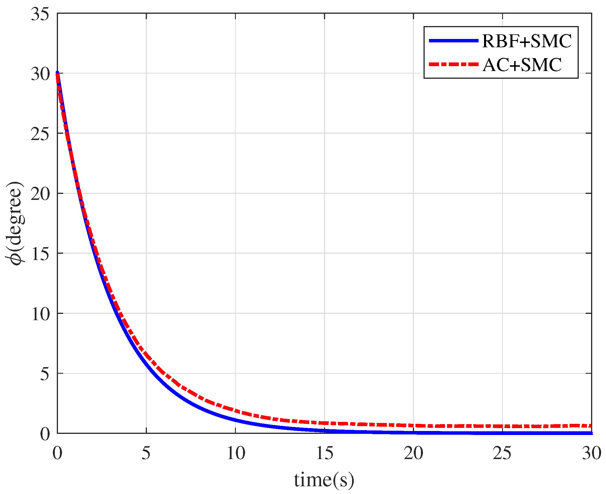
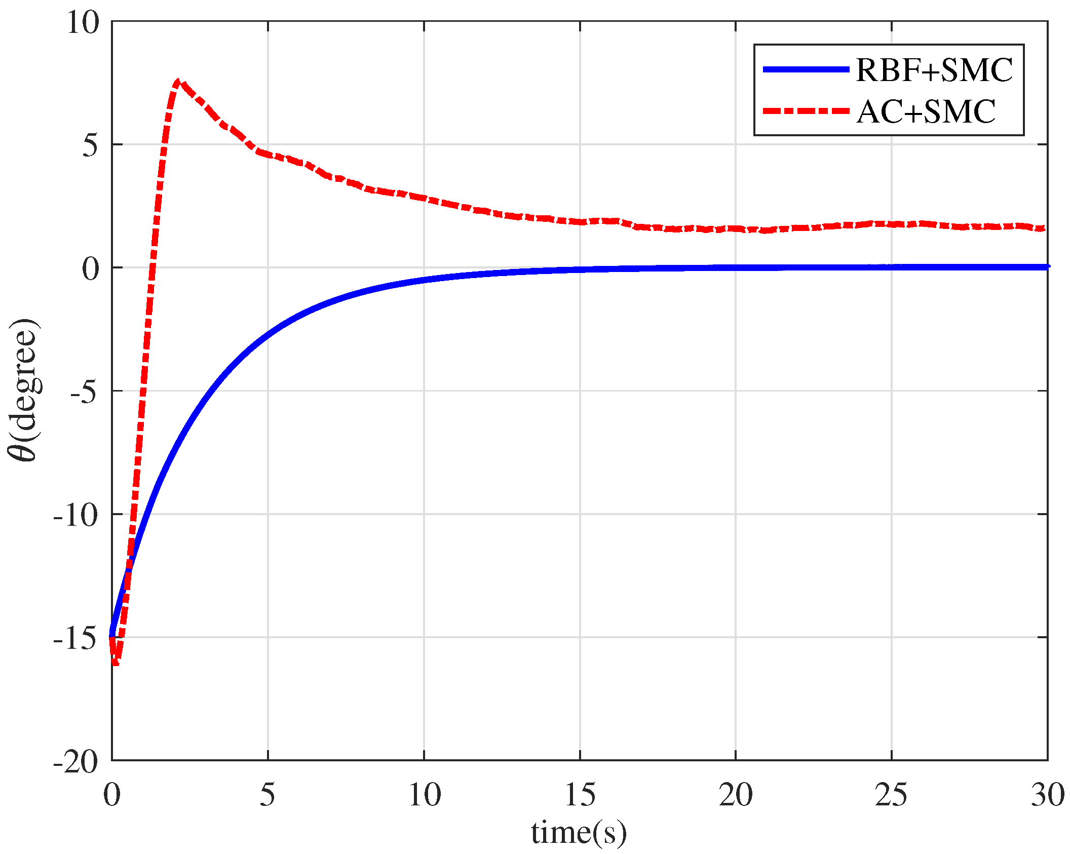
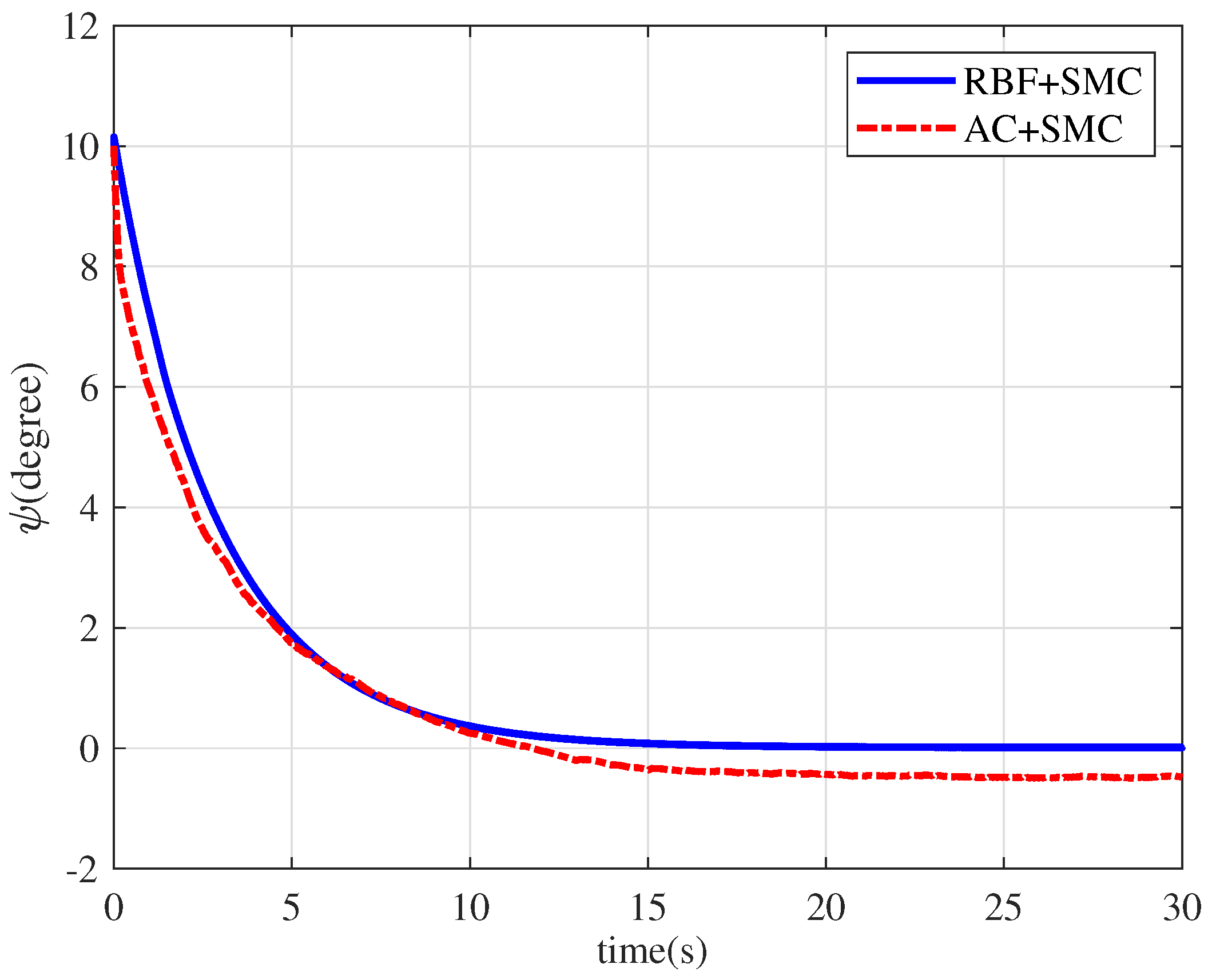
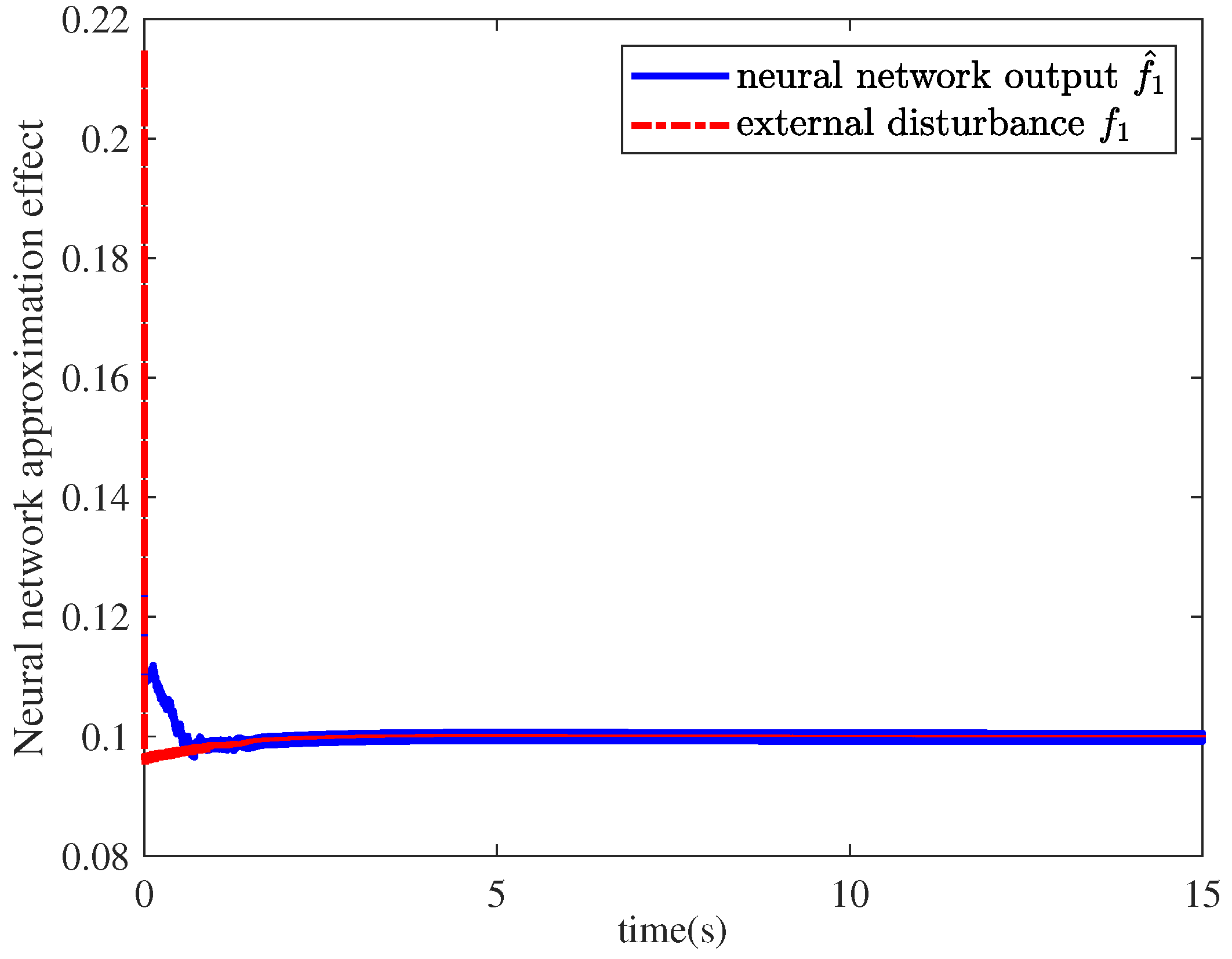
In this paper, we proposed an adaptive sliding-mode control algorithm in the delta domain for the attitude control of a quadrotor UAVs subject to external disturbances and couplings. First, the delta operator technique was used to discretize the attitude system of a quadrotor UAV. Then, a linear sliding surface, which can ensure the asymptotic stability of the sliding dynamics, was introduced in terms of the linear matrix inequality technique. Second, an adaptive sliding mode controller, using an RBF neural network to estimate external disturbances and couplings, was designed for the attitude reaching control.
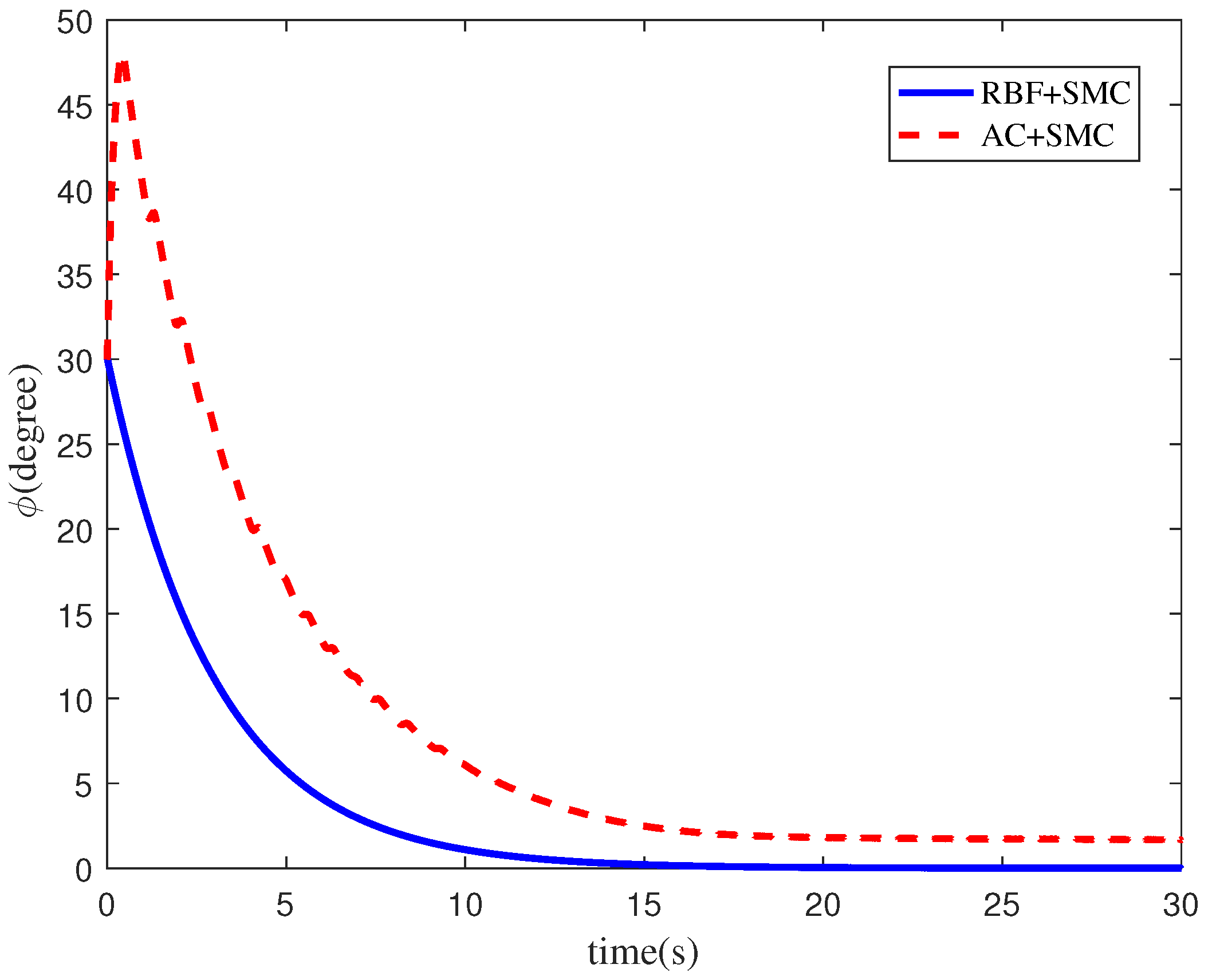
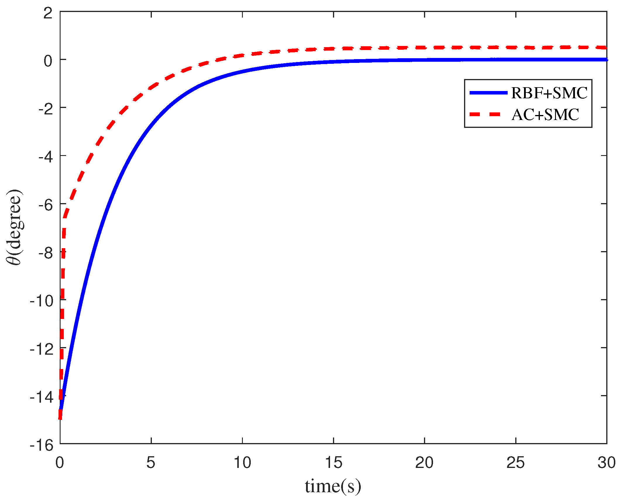
We demonstrated, via Lyapunov stability theory, that the controller guaranteed that all attitudes of the quadrotor UAVs could be driven to the designed sliding surface, and thus attitude control was achieved. Finally, simulation result comparisons verified the effectiveness and superiority of the proposed adaptive sliding-mode attitude control algorithm proposed in this paper. In our future research, how to apply the proposed theoretical method to an actual unmanned system will be our focus and will be studied in depth.

Author Contributions

Conceptualization, B.Z.; formal analysis, Y.W., investigation, H.L.; software, Z.C.; Writing—review and editing, B.Z.; writing—original draft preparation, Y.W. and H.L.; Z.C. provided support in the whole writing of this paper. All authors have read and agreed to the published of the manuscript.

Funding

This research was funded by the National Natural Science Foundation of China under grant number 61973169, the Jiangsu Natural Science Foundation under grant number BK20201392, the Qing Lan Project of Jiangsu Province under grant number R2021Q04.

Institutional Review Board Statement

Not applicable.

Informed Consent Statement

Not applicable.

Data Availability Statement

Not applicable.

Conflicts of Interest

The authors declare no conflict of interest.

References

  1. Noordin, A.; Basri, M.A.M.; Mohamed, Z.; Lazim, I.M. Adaptive PID controller using sliding mode control approaches for quadrotor UAVs attitude and position stabilization. Arab. J. Sci. Eng. 2021, 46, 963–981. [Google Scholar] [CrossRef]
  2. Wang, S.Y.; Polyakov, A.; Zheng, G. Quadrotor stabilization under time and space constraints using implicit PID conttroler. J. Frankl. Institude 2022. [Google Scholar] [CrossRef]
  3. Sun, C.; Liu, M.; Liu, C.; Feng, X.; Wu, H. An industrial quadrotor UAVs control method based on fuzzy adaptive linear active disturbance rejection control. Aerosp. Sci. Technol. 2020, 10, 376. [Google Scholar] [CrossRef]
  4. Wang, Z.J.; Zhao, T. Adaptive-based linear active disturbance rejection attitude control for quadrotor with external disturbances. Trans. Inst. Meas. Control 2022, 44, 286–298. [Google Scholar] [CrossRef]
  5. Zhang, Y.; Nie, Y.; Chen, L. Adaptive fuzzy fault-tolerant control against time-varying faults via a new sliding mode observer method. Symmetry 2021, 13, 1615. [Google Scholar] [CrossRef]
  6. Hong, Q.; Shi, Y.; Chen, Z. Adaptive sliding mode control based on disturbance observer for placement pressure control system. Symmetry 2020, 12, 1057. [Google Scholar] [CrossRef]
  7. Xiong, J.J.; Zhang, G.B. Discreti-time sliding mode control for a quadrotor UAV. Optik 2016, 127, 3718–3722. [Google Scholar] [CrossRef]
  8. Wu, X.W.; Xiao, B.; Qu, Y.H. Modeling and sliding mode-based attitude tracking control of a quadrotor UAVs with time-varying mass. ISA Trans. 2019. [Google Scholar] [CrossRef]
  9. Hou, Z.; Lu, P.; Tu, Z. Nonsingular terminal sliding mode control for a quadrotor UAVs with a total rotor failure. Electronics 2021, 98, 105716. [Google Scholar] [CrossRef]
  10. Yang, S.Y.; Han, J.; Xia, L.; Chen, Y.-H. Adaptive sliding mode attitude controller such that all attitudes of the quadrotor UAVs can be driven to the designed sliding surface. ISA Trans. 2021, 106, 12–30. [Google Scholar] [CrossRef]
  11. Zhang, J.; Ren, Z.; Deng, C.; Wen, B. Adaptive fuzzy global sliding mode control for trajectory tracking of quadrotor UAVs. Nonlinear Dyn. 2019, 97, 609–627. [Google Scholar] [CrossRef]
  12. Nekoukar, V.; Dehkordi, M.M. Robust path tracking of a quadrotor using adaptive fuzzy terminal sliding mode control. Control. Eng. Pract. 2021, 110, 104763. [Google Scholar] [CrossRef]
  13. Eliker, K.; Zhang, W. Finite-time adaptive integral backstepping fast terminal sliding mode control applications on quadrotor UAV. Int. J. Control. Autom. Syst. 2020, 18, 415–430. [Google Scholar] [CrossRef]
  14. Zhang, X.; Wang, Y.; Zhu, G.; Chen, X.; Su, C.-Y. Discrete-time adaptive neural tracking control and its Enperiments for quadrotor unmanned aerial vehicle systems. IEEE/ASME Trans. Mechatronics 2022. [Google Scholar] [CrossRef]
  15. Middleton, R.; Goodwin, G.C. Improved finite word length characteristics in digital control using delta operators. IEEE Trans. Automat. Contr. 1986, 31, 1015–1021. [Google Scholar] [CrossRef]
  16. Middleton, R.H.; Goodwin, G.C. Digital Control and Estimation: A Unified Approach; Prentice Hall: Hoboken, NJ, USA, 1990. [Google Scholar]
  17. Zheng, B.C.; Yu, X.; Xue, Y. Quantized sliding mode control in delta operator framework. Int. J. Robust Nonlinear Control 2018, 28, 519–535. [Google Scholar] [CrossRef]
  18. Yang, H.; Xia, Y.; Shi, P.; Zhao, L. Analysis and Synthesis of Delta Operator Systems; Springer: Berlin/Heidelberg, Germany, 2012. [Google Scholar]
  19. Sakthivel, R.; Ramya, L.S.; Ma, Y.K.; Malik, M.; Leelamani, A. Stabilization of uncertain switched discrete-time systems against actuator faults and input saturation. Nonlinear-Anal.-Hybrid Syst. 2020, 35, 519–535. [Google Scholar] [CrossRef]
  20. Guo, X.; Yang, G.-H. Insensitive output feedback H-infinity control of delta operator systems with insensitivity to sampling time jitter. Int. J. Robust Nonlinear Control 2014, 24, 725–743. [Google Scholar] [CrossRef]
  21. Guo, X.; Yang, G.-H. Low-sensitivity H filter design for linear delta operator systems with sampling time jitter. Int. J. Control 2012, 85, 397–408. [Google Scholar] [CrossRef]
  22. Pu, X.; Ren, L.; Liu, Y.; Ji, L.H. Group consensus of multi-agent systems with cooperative-competitive interaction and communication delay in switching topologies networks based on the delta operator method. Neurocomputing 2020, 390, 57–68. [Google Scholar] [CrossRef]
  23. Pu, X.; Ren, L.; Liu, Y.; Pu, R. Couple-group consensus for heterogeneous MASs under switched topologies in cooperative-competitive systems: A hybrid pinning and delta operator skills. Neurocomputing 2021, 441, 335–349. [Google Scholar] [CrossRef]
  24. Chen, G.S. Study on Anti-Jamming and Fault-Tolerant Control of Quadrotor UAV; Nanjing University of Information Science and Technology: Nanjing, China, 2020. [Google Scholar] [CrossRef]
  25. Zhang, Z.C. Sliding Mode Fault-Tolerant Control Algorithm for Delta Operator Time-Delay Systems; Nanjing University of Aeronautics and Astronautics: Nanjing, China, 2016. [Google Scholar]
  26. Zhao, B.; Xian, B.; Zhang, Y.; Zhang, X. Nonlinear robust adaptive tracking control of a quadrotor UAVs via immersion and invariance methodology. IEEE Trans. Ind. Electron. 2015, 62, 2891–2902. [Google Scholar] [CrossRef]
  27. Lendoul, F.; Lara, D.; Fantoni-Coichot, I.; Lozano, R. Real-time nonlinear embedded control for an autonomous quadrotor helicopter. J. Guid. Control. Dyn. 2007, 30, 1049–1060. [Google Scholar] [CrossRef]
  28. Zhao, D.; Sun, C.; Wang, Q.; Yang, W. Neural-network-based PID control for quadrotor aircraft. In Proceedings of the International Conference on Intelligent Science and Big Data Engineering; Springer: Cham, Switzerland, 2015; pp. 287–297. [Google Scholar]
  29. Wang, W.; Ma, H.; Xia, M.; Weng, L.; Ye, X. Attitude adn altitude controller design for quad-rotor type MAVs. Math. Probl. Eng. 2013, 2013, 587098. [Google Scholar]
  30. Wang, S.B.; Han, Y.; Chen, J.; Zhang, Z.C.; LIu, X.Z. Attitude active disturbance rejection control of UAVs attitude based on iterative learning control. Acta Aeronaut. Astronaut. Sin. 2020, 41, 324112. (in Chinese) [Google Scholar] [CrossRef]
  31. Du, H.; Zhu, W.; Wen, G.; Wu, D. Finite time formation control for a group of quadrotor aircraft. Aerosp. Sci. Technol. 2017, 69, 609–616. [Google Scholar] [CrossRef]
  32. Li, H.; Wu, B.; Li, G.; Yang, C. Global Theory of Delta Operator Control and Its Robustness Control; National Defense Inddustry Press: Beijing, China, 2005. [Google Scholar]
  33. Boyd, S.; El Ghaoui, L.; Feron, E.; Balakrishnan, V. Linear matrix inequalities in system and control theory. In Society for Industrial and Applied Mathematics; Society for Industrial and Applied Mathematics: Philadelphia, PA, USA, 1994. [Google Scholar]
  34. Liu, J. Intelligent Control Design and MATLAB Simulation; Tsinghua University Press: Beijing, China; Springer Nature Singapore Pte Ltd.: Singapore, 2018. [Google Scholar]
Figure 1. RBF neural network structure diagram.
Symmetry 14 00498 g001
Figure 2. Diagram of the RBF neural-network-based adaptive sliding-mode control algorithm.
Symmetry 14 00498 g002
Figure 3. Response results of the attitude angle ϕ .
Symmetry 14 00498 g003
Figure 4. Response results of the attitude angle θ .
Symmetry 14 00498 g004
Figure 5. Response results of the attitude angle ψ .
Symmetry 14 00498 g005
Figure 6. Neural network approximation results of the external disturbance f 1 ( t k ) .
Symmetry 14 00498 g006
Figure 7. Neural network approximation results of the external disturbance f 2 ( t k ) .
Symmetry 14 00498 g007
Figure 8. Neural network approximation results of the external disturbance f 3 ( t k ) .
Symmetry 14 00498 g008
Figure 9. Response results of the attitude angle ϕ .
Symmetry 14 00498 g009
Figure 10. Response results of the attitude angle θ .
Symmetry 14 00498 g010
Figure 11. Response results of the attitude angle ψ .
Symmetry 14 00498 g011
Figure 12. Neural network approximation results of the external disturbance f 1 ( t k ) .
Symmetry 14 00498 g012
Figure 13. Neural network approximation results of the external disturbance f 2 ( t k ) .
Symmetry 14 00498 g013
Figure 14. Neural network approximation results of the external disturbance f 3 ( t k ) .
Symmetry 14 00498 g014
Table 1. Physical parameters of the quadrotor UAV.
ParametersValuesUnits
m2.5kg
l0.245m
g9.8m/s 2
c0.575m
K 1 0.148N s/m
K 2 0.148N s/m
K 3 0.164N s/m
J 1 0.05kg·m 2
J 2 0.05kg·m 2
J 3 0.12kg·m 2
Table 2. Controller parameters of the quadrotor UAV.
Attitude Angle Systems ε i β i γ i
Roll angle system1002030
Pitch angle system2002030
Yaw angle system1202040
Table 3. Steady-state time of attitude angle under different control algorithms.
Attitude Angle SystemsRoll Angle SystemPitch Angle SystemYaw Angle System
RBF + SMC16.8 s15.2 s13.7 s
AC + SMC///
Table 4. Approximation time of RBF neural network to f i ( t ) .
Attitude Angle SystemsRoll Angle SystemPitch Angle SystemYaw Angle System
Effective approximation time4.6 s7.5 s1.45 s
Table 5. Controller parameters of the quadrotor UAVs proposed in [25].
Attitude Angle Systems μ i
Roll angle system4
Pitch angle system3
Yaw angle system4
Table 6. Controller parameters of the quadrotor UAVs proposed in this paper.
Attitude Angle Systems ε i β i γ i
Roll angle system1202010
Pitch angle system200205
Yaw angle system300205
Table 7. Steady-state time of attitude angle under different control algorithms.
Attitude Angle SystemsRoll Angle SystemPitch Angle SystemYaw Angle System
RBF + SMC15.7 s13.7 s16.4 s
AC + SMC21.6 s/25.8 s
Table 8. Approximation time of RBF neural network to f i ( t ) .
Attitude Angle SystemsRoll Angle SystemPitch Angle SystemYaw Angle System
Effective approximation time1.63 s1.79 s2.06 s
Publisher’s Note: MDPI stays neutral with regard to jurisdictional claims in published maps and institutional affiliations.

