1. Introduction
In recent years, with the development of renewable energy generation technology, microgrids using new energy sources have become effective ways to solve the conflict between energy demand and environmental protection. When a microgrid is connected to a grid, the protection device will disconnect the microgrid from the external grid if a fault occurs in the external power grid. However, when grid-connected power is high, the unplanned removal of a microgrid may lead to grid power imbalance and affect the safe and stable operation of the system; therefore, the microgrid system should have FRT capability to reduce the impact of off-grid events caused by external faults [
1].
The fault current limiter (FCL) is an effective measure to limit short-circuit current in power systems. With the improvement of its power quality-control function, its application scenarios have been expanded. For microgrid systems, a FCL can limit fault current, reduce bus voltage sag and improve FRT capability.
At present, a considerable number of articles have reported research on superconducting FCLs to improve the FRT capability of microgrids [
2,
3,
4]. The results show that FCLs of this sort can limit short-circuit current and improve the FRT of systems, but these FCLs have some problems, such as high dependence on cooling systems and long recovery times after operation. Relying on power electronic devices, the solid-state FCL has better controllability and fast action speed. However, limited by the device’s low withstand voltage level and current withstand level, this type of FCL cannot be widely used at present [
5,
6,
7]. The current work on the abovementioned FCLs to enhance the FRT capability of microgrids mainly focuses on fault current limiting, and the voltage regulation capability of FCLs has not been studied in depth. In Ref. [
8], a dynamic voltage restorer (DVR) with current limiting function was proposed which limits short-circuit current by inputting current limiting impedances in the grid during faults and switches to DVR working mode after the fault is cleared. However, this scheme still has some problems that need to be solved, such as high heat dissipation requirements and the insufficient withstand voltage of devices. In ref. [
9], the cascaded H-bridge flexible fault current limiter (CHB-FFCL) was proposed, which is connected to the grid through capacitive coupling instead of a transformer, thereby reducing the device size of the FCL. In addition, the cascaded multi-level structure adopted has the advantages of large capacity, good output characteristics, flexible controllability, etc., and reduces the withstand voltage and current of a single power electronic device. Therefore, applying the CHB-FFCL to improve the FRT of a microgrid can overcome many practical application problems that beset traditional FCLs.
Since the negative sequence components of unbalanced grid voltage will have a serious impact on the quality of PCC voltage, it is of great importance to study the recovery control strategy for PCC voltage under the condition of unbalance [
10]. In ref. [
11], a PCC voltage control scheme based on a sliding mode structure was proposed which can reduce the impact of grid voltage disturbance on PCC voltage. However, this scheme did not consider the influence of grid unbalanced voltage.
Considering the three-phase independent structure of the CHB-FFCL and the flexible output characteristics of the multi-level inverter structure, the CHB-FFCL has advantages in dealing with unbalanced grid faults. Usually, the realization of its control requires the obtainment of amplitude and phase angle information on the electric quantities through PLL. However, the feedback control-based PLL technique suffers from weak anti-interference capability and poor dynamic performance [
12], especially in the case of an unbalanced power grid. For this reason, many scholars have proposed improved schemes for PLL. In ref. [
13], the first-order low-pass filter (LPF) was used in the control structure of the traditional PLL to eliminate the impact of negative sequence or harmonic voltage components, but the delay and phase offset of the LPF affected the identification speed of the PLL. Therefore, in ref. [
14], a notch filter was used to replace the first-order LPF to improve the stability of PLL. However, if the grid voltage contains multiple disturbance components, it is necessary to connect multiple notch filters with different frequencies in series, which increases the difficulty of PLL implementation and computational burden. In ref. [
15], a positive-sequence fundamental frequency voltage component extraction method based on a differential equation was proposed which ensures that PLL is free from the influence of non-ideal voltage components. However, due to the differential calculation involved, the anti-interference performance of the system is reduced. The abovementioned improvement scheme increases the order of PLL and the poles of the original closed-loop transfer function, which may reduce the stability margin for PLL and cause instability in PLL. In addition, impedance modeling analysis shows that the introduction of PLL increases the coupling between system parameters in a grid-connected inverter system. Moreover, the increase in proportional or integral parameters in PLL will lead to large amplitude and phase fluctuations in the fundamental frequencies of the inverter impedance characteristics, which will lead to potential system stability problems [
16,
17]. Therefore, it is necessary to study the inverter control scheme without PLL to overcome the abovementioned problems caused by PLL. In refs. [
18,
19], the control scheme for an inverter without PLL based on preset rotational frequency was studied which improved the operating performance of a DFIG in an unbalanced grid. However, this strategy cannot adapt to grid frequency offset.
To address these problems, this paper analyzes the principle of achieving FRT with the CHB-FFCL as the research object. The dq-axis components are extracted without PLL in a double synchronous rotating coordinate system by setting the rotation angular frequency of the coordinate axis. Aiming to solve the problem of the set frequency deviating from the frequency of the grid, a calculation formula for frequency correction is derived. Through iterative correction, the set frequency can be corrected without feedback control. A sequence decomposition and compensation control strategy for the CHB-FFCL is presented. Finally, through simulation analysis, the effectiveness of the above strategy is verified.
2. The Topological Structure and Working Principle of the CHB-FFCL
The topology of the CHB-FFCL is shown in
Figure 1, where
US is the power supply on the distribution grid side and
UMG is the power source on the microgrid side. It adopts a three-phase independent inverter structure with independent control of each phase, aiming to reduce the coupling between the three phases and more flexibly cope with three-phase unbalanced faults. In the figure,
Cai/bi/ci and
Lai/bi/ci (i = 1...m) are the filter partial-voltage capacitors and filter inductors of CHB-FFCL, n and m represent the number of cascades and the number of partial-voltage capacitors (also called the number of multiples) of each phase of the CHB-FFCL, and
Udc is the DC side voltage of the H-bridge inverter, which is supplied by the distributed generation (DG). By connecting m partial-voltage capacitors in series and connecting n H-bridge units in cascade, the voltage drop added to an individual power electronic device is greatly reduced, and it is also convenient to expand the capacity of the CHB-FFCL.
Based on this topology, the operating principle of the CHB-FFCL for achieving both fault voltage recovery and fault current limitation is discussed.
Firstly, the regulation effect of the CHB-FFCL on PCC voltage when a fault occurs outside the microgrid is discussed.
As shown in
Figure 2a, when a fault occurs outside the microgrid, the CHB-FFCL can be equivalent to a voltage-controlled voltage source (VCVS), which is shown in
Figure 2b. The output voltage of the VCVS is
UC, and for the fault point f the direction of
UC is opposite to the direction of the microgrid supply voltage
UMG. The voltage of the bus W can be expressed as:
where
is the voltage of bus W in case of a fault without the CHB-FFCL, and its value is equal to the voltage of short-circuit point f when the line impedance between the short-circuit point f and bus W is not considered. It can be seen from Equation (1) that by controlling the output voltage
of the CHB-FFCL, the bus W voltage can be compensated, thereby reducing the voltage sag of the PCC.
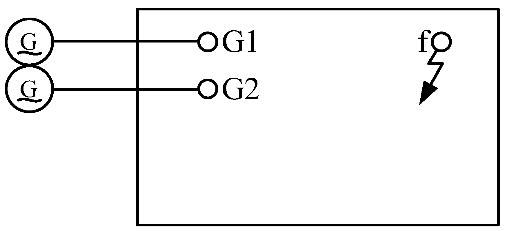
Next, this paper analyzes the current limiting principle of the CHB-FFCL when a fault occurs. The system in
Figure 1 can be equivalent to a complex power system shown in
Figure 3, where G1 is the distribution network power endpoint and G2 is the microgrid power endpoint.
According to the symmetrical component method, the short-circuit fault current of this power system is analyzed using the general compound sequence network. Taking the two-phase (phase
b and phase
c) short-circuit fault at point f as an example and considering the boundary conditions, the short-circuit current expression of fault phase without the CHB-FFCL is obtained as follows:
where
and
and
represent the positive and negative sequence currents flowing into the fault point, respectively;
is the open-circuit voltage at point f when no fault occurs; and
and
are the positive sequence and negative sequence equivalent impedances viewed from fault point f, respectively.
The CHB-FFCL is switched on when a fault occurs, which is equivalent to connecting a voltage source whose value is k (0 ≤ k ≤ 1)
and whose direction is opposite to the power supply voltage in series, as shown in
Figure 4. In this case, the open-circuit voltage at fault point f is reduced to 1-k times the original value, and the short-circuit current of the corresponding fault phase is reduced to:
Similarly, when other types of short-circuit fault occur on the distribution network side, combined with ref. [
20], the corresponding fault current expression after the CHB-FFCL input can be obtained according to the above analysis method. It can be seen from
Figure 2 that the fault current is the current flowing through the PCC during the fault.
Comprehensive analysis shows that the structure of the CHB-FFCL ensures the control of output voltage, which helps to realize the dual function of voltage regulation and current limitation in case of a fault, thus improving the FRT capability of the microgrid.
3. The Non-PLL Control Principle of the CHB-FFCL in a Decoupled Double Synchronous Rotating Coordinate System
When designing the controller, compared with the scheme for controlling the AC signal in three-phase and two-phase stationary coordinates, converting the AC signal to the DC quantity in
dq rotating coordinates for PI control can better realize the zero steady-state error characteristics of the control [
21,
22]. Ignoring coupling disturbance, when the load is only powered by CHB-FFCL, its
d-axis voltage and current double closed loop control block diagram is shown in
Figure 5. In the figure,
Gv(s) and
Gi(s) are PI regulators of voltage loop and current loop, respectively; the electric quantities with the subscript “refd” represent the corresponding
d-axis reference values; the subscript “od” indicates the value of the load; and
Kpwm is the inverter gain.
The q-axis electrical quantities have the same control structure and each order’s harmonic quantities can be controlled through the control loop, and the controlling vectors are synthesized and outputted. Therefore, obtaining the dq-axis components of the electric quantity for each order is a prerequisite for realizing the above CHB-FFCL control strategy.
In this paper, the current is taken as the object of analysis, and the voltage component is subjected to the same analytical process.
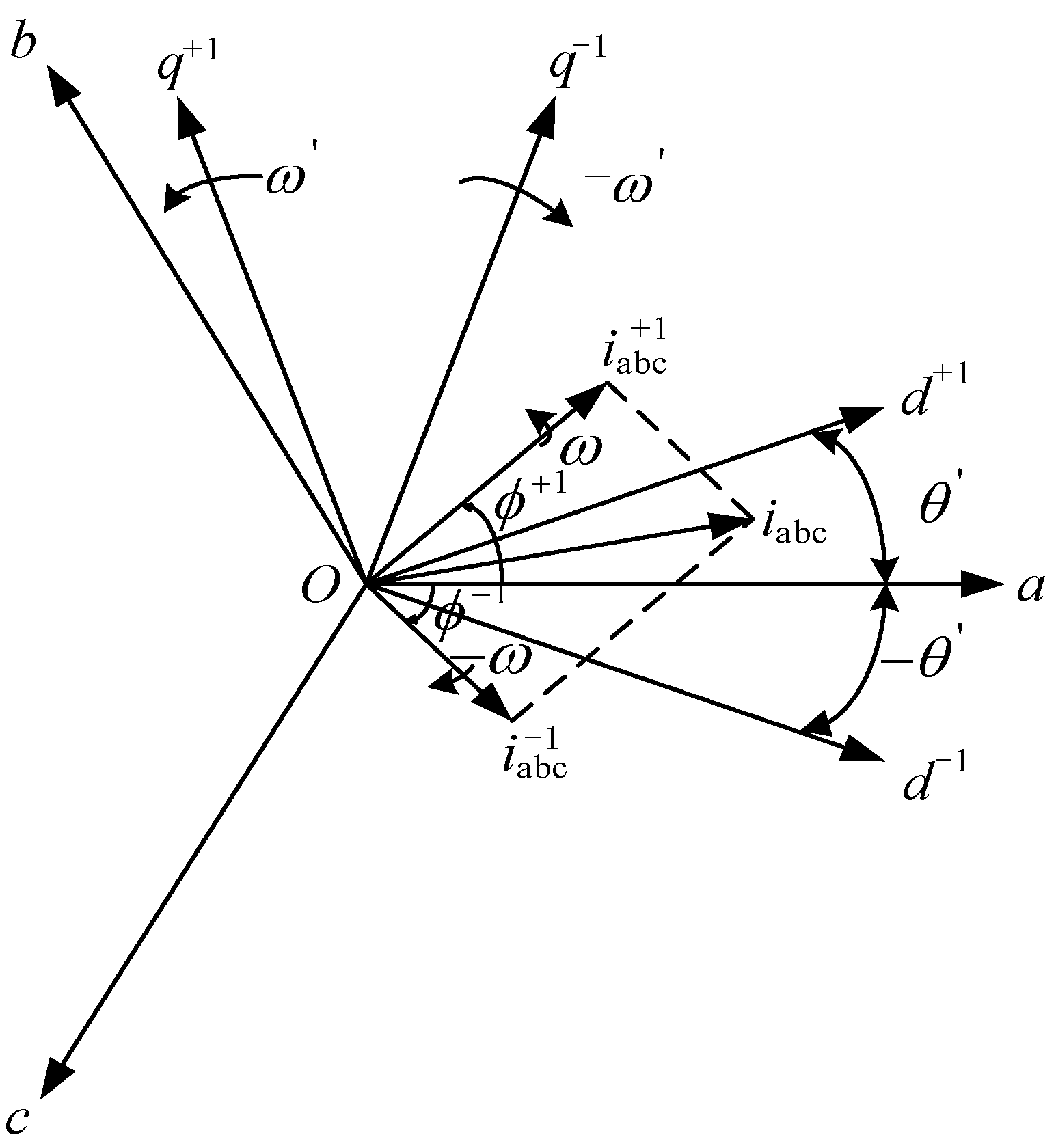
Referring to the principle of the decoupled double synchronous reference frame phase-locked loop (DDSRF-PLL), positive sequence and negative sequence rotation coordinate systems are added to the static
abc three-phase coordinate system, as shown in
Figure 6. When the synchronization condition is reached, Equation (5) is established. After that, Equation (6) is transformed into Equation (7), so the required positive and negative sequence
dq-axis DC electrical components can be extracted through the decoupling network and low-pass filter [
23]. In addition, the decoupling network of the DDSRF-PLL cancels out the double frequency oscillations at 2
ω in
(feedback control estimates the current of the DDSRF-PLL); therefore, there is no need to reduce the control loop bandwidth, and the real amplitudes of the positive sequence and negative sequence components can be exactly detected. The amplitudes of positive sequence and negative sequence components can be obtained from Equation (8).
DDSRF-PLL achieves the above synchronization conditions through PLL, but this method has problems, such as frequency oscillation and poor anti-interference. According to the national standard, the power frequency of the power grid is a stable quantity. Therefore, the synchronization condition can be guaranteed by directly setting the rotation angular frequency of the rotating coordinate system to be equal to the angular frequency corresponding to the power frequency, so that the dq-axis DC electrical components can be extracted without PLL.
4. Frequency Adaptive Correction Strategy of The Proposed Non-PLL Method
The realization of the abovementioned non-PLL method and the corresponding control strategy presupposes that the given angular frequency of the rotating coordinate system is the same as the angular frequency ω of the fundamental wave of the power grid, which requires the power frequency of the power grid to remain constant. However, in national regulations, the actual frequency of the power grid is not constant but fluctuates within a certain range. Taking the Chinese standard as an example, the nominal frequency of the power grid is 50 Hz, the frequency offset of high-capacity power grids cannot exceed ±0.2 Hz and the frequency offset of low-capacity power grids can be relaxed to ±0.5 Hz. Therefore, there is an error between the given and the fundamental angular frequency of the power grid, and an adaptive correction of the frequency is required.
It is assumed that there is a deviation Δ
ω between the rotation angular frequency of the given positive sequence fundamental wave rotating coordinate system and the actual power grid fundamental wave rotation angular frequency
ω, as shown in Equation (9):
then
Taking the positive sequence fundamental current into consideration, Equation (7) is converted into Equation (11), and, similarly, the same equation structure can be deduced when considering the negative sequence fundamental current.
It can be seen from Equation (11) that in the case of deviation the
dq-axis component is composed of two AC oscillation quantities. According to the Chinese national standard, the value of Δ
ω is within [−π, π]. Obviously,
ω is much larger than Δ
ω, and therefore the first AC quantity “AC1” in Equation (11) can be retained after passing through the low-pass filter. As a result, the decoupling network [
23] regards the first AC quantity “AC1” in Equation (11) as the DC quantity obtained after filtering.
Through the decoupling network, the decoupling expression of the positive sequence current is obtained, as shown in Equation (12). Inserting Equation (7), Equation (10) and the first AC quantity of Equation (11) into Equation (12), the estimated value of the
dq-axis DC quantity can be obtained, as shown in Equation (13).
From Equation (13), it is not difficult to see that, after decoupling, the obtained dq-axis DC estimator is the first AC component of Equation (11), which indicates that the decoupling network is still applicable in the case of frequency deviation. However, the dq-axis components obtained in this case are AC components, and it is difficult to obtain the target electric quantity in the control of CHB-FFCL. Therefore, it is necessary to correct the given frequency.
According to the analysis of Equation (13), in the case of frequency deviation, the frequency deviation amount can be calculated by the
dq-axis DC estimated value obtained without PLL, and the calculation formula is shown in Equation (14).
The deviation of the given frequency between the actual power grid frequency can be determined by Equation (14), and so the adaptive correction of frequency can be realized.
It is worth noting that in the case of no feedback control on the given frequency, directly adding the correction amount calculated each time to the initial given frequency will lead to a large amplitude oscillation in the set frequency. Therefore, during frequency correction, the correction amount should only be superimposed on the initial given frequency the first time and then on the latest corrected frequency. The correction process is an iterative process, and the expression is shown as follows:
where
is the set frequency after
n times of correction;
is the initial given frequency, which is usually taken as the power frequency of the power grid; and
is the amount of deviation correction between
and the actual grid frequency.
Based on the above analysis, combined with the inverter dual-loop control strategy [
24], the sequence decomposition and compensation control strategy of the CHB-FFCL without PLL is obtained, as shown in
Figure 7.
Combining the control block diagram shown in
Figure 5, ignoring the inductor’s resistance, the open-loop transfer function of the control system can be obtained, as shown in Equation (16).
where
and
Uc is the amplitude of the triangular carrier wave, the value here being 1;
ωc is the bandwidth of the controller; and
ω0 is the resonant frequency.
Through this control strategy, the flexible control of the output voltage of the CHB-FFCL is realized, thereby improving the FRT capability of the microgrid in the case of asymmetric faults.
5. Simulation and Discussion
5.1. Effectiveness Analysis of the Proposed Non-PLL Strategy
The three-phase asymmetric fault was set in the simulated power grid, and the resultant current waveform is shown in
Figure 8. In the figure, when there was no fault, the three-phase current amplitude was 10 A, and the initial phase angle was 0°. During 0.3–0.5 s, the positive sequence fundamental current and negative sequence fundamental current were injected into the power grid. The amplitude and initial phase angle of the former were 20 A and 45°, respectively. The amplitude and initial phase angle of the latter were 10 A and −15°, respectively. The three-phase asymmetric fault in the power grid could be simulated. DDSRF-PLL and the proposed non-PLL strategy were respectively used to extract the
dq-axis components of the positive and negative sequence fundamental currents of the power grid.
Since the proposed non-PLL scheme only needs to ensure that the angular frequency of the rotating coordinate system is equal to the angular frequency of the positive sequence fundamental electric quantity, it does not need to ensure that the initial phase angle is equal to it, which is different from the DDSRF-PLL method. Therefore, for the same asymmetric current vector, when the output values of the DDSRF-PLL and the proposed non-PLL scheme reach a steady state, their phase angles for the generated dual synchronous reference coordinate axis relative to the stationary coordinate axis of phase a are different, so the DC electrical quantity components extracted by the two methods are also different. However, for the same asymmetric electric quantity, the amplitudes of the positive sequence and negative sequence fundamental electric quantities obtained from Equation (8) are equal. Therefore, this study first compared the extracted amplitudes to verify the effectiveness of the proposed non-PLL scheme and set the DDSRF-PLL bandwidth to 38.4 Hz. The simulation results are shown in
Figure 9.
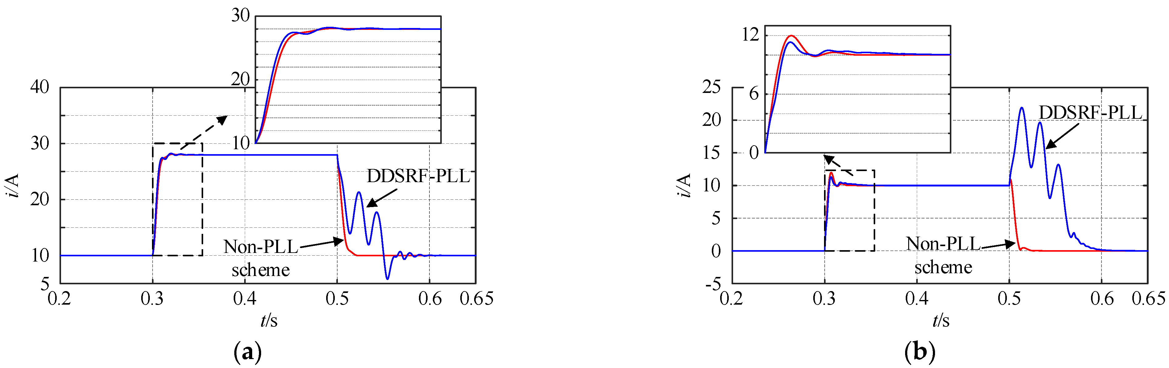
It can be seen that the proposed non-PLL scheme and DDSRF-PLL could quickly extract the amplitudes of positive and negative sequence fundamental currents when a fault occurred (0.3 s), and the extracted results conformed to the parameters of the set fault (positive sequence fundamental current vector: i+1 = 10∠0° + 20∠45° = 28∠30.36°A; negative sequence fundamental current vector: i−1 = 10∠−15°). It can be seen from the detailed diagram that the proposed non-PLL scheme could reach the new stable state more quickly and smoothly than DDSRF-PLL. At the end of the fault, DDSRF-PLL was prone to oscillate for a long time, and the proposed non-PLL scheme still had good stability performance.
Then, the performances of these two methods were compared to extract each
dq-axis DC component. The
dq-axis DC components of each sequence current mapped in the double synchronous reference coordinate system were extracted, as shown in
Figure 10. In the figure,
and
are, respectively, the transition times required for the non-PLL scheme and DDSRF-PLL to reach a new steady state when a fault occurs. Comparing
and
, the dynamic characteristics of the proposed scheme can be measured.
It can be seen from
Figure 10a–d that the tracking results of other axes all satisfied the relationship
<
, except that the
q+-axis used for DDSRF-PLL feedback control satisfied the relationship
>
and the
value on the other three axes was obviously greater than that on the
q+-axis. This shows that in case of a fault, given the premise that the control parameters of the DDSRF-PLL are appropriate (shown as the short transition time of the
q+-axis), the DDSRF-PLL has a speed advantage only when detecting the DC components on the controlled axis and that the advantage is relatively insignificant, while the speed of reaching the steady state value in the other three axes is significantly slower than with the proposed non-PLL scheme. In addition, at the end of the fault, the DDSRF-PLL had large oscillations in the transition phase of the four axes, and the transition time was long. As a comparison, the proposed non-PLL scheme could still maintain a smooth and rapid transition with excellent dynamic characteristics.
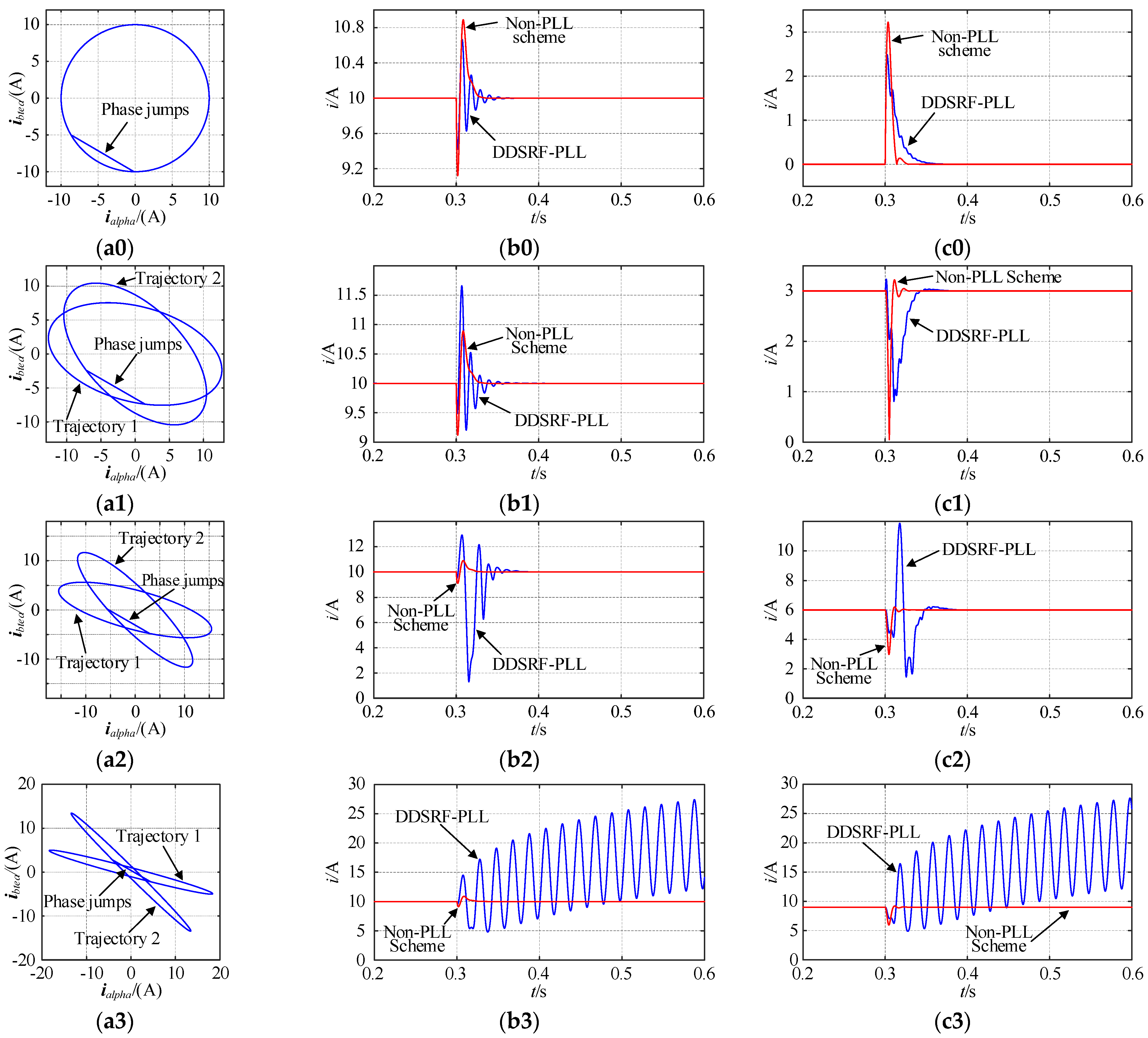
When phase jumps occur in electrical quantities, PLL based on feedback control is prone to instability, while the non-PLL scheme can better deal with phase jumps due to the fact that a feedback control loop is not required. In this study, the phase jumps of current in the three-phase unbalanced system were simulated and analyzed. The amplitudes of positive sequence and negative sequence fundamental currents were extracted through the non-PLL scheme and DDSRF-PLL, respectively, and the results are shown in
Figure 11. The amplitude of the positive sequence fundamental current was 10 A, and the initial phase angle was 0°. Setting the negative sequence unbalance factor to 0%, 30%, 60% and 90%, respectively, we obtained simulation results with the corresponding labels “0”, “1”, “2” and “3”. At 0.3 s, the phase of the positive sequence fundamental current jumped −60°; the jump process can be clearly seen in
Figure 11a. In the figure, trajectories 1 and 2 are current vector trajectories before and after phase jumps respectively. It can be seen from the extraction results for positive sequence and negative sequence fundamental amplitudes in
Figure 11b,c that the impact of phase jumps on DDSRF-PLL was significantly greater than for the non-PLL scheme. With the increase in grid unbalance, the impact on DDSRF-PLL also increases. When the negative sequence unbalance factor is too large (such as 90%), DDSRF-PLL cannot recover to a stable state. As a comparison, the non-PLL scheme was less affected and could quickly self-recover to the stable operation state. With the increase in grid unbalance, the impact on the extraction of positive sequence components did not increase significantly. This scheme has good stability.
5.2. Effectiveness Verification of the Proposed Frequency Adaptive Correction Method
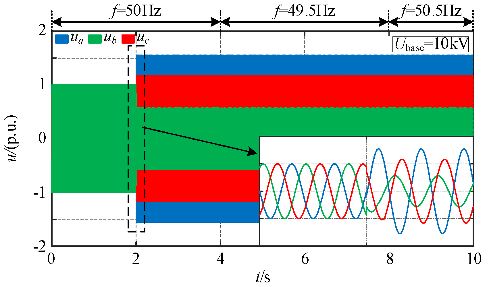
To verify the effectiveness of the proposed self-adaptable frequency rectifying method, it was assumed that a complex three-phase fault occurred in the power grid; its voltage waveform is shown in
Figure 12. Within 0–2 s, the power grid operated normally without fault. Starting from 2 s, a negative sequence fundamental voltage component with an amplitude of 0.6 p.u. and an initial phase angle of −30° was superimposed on the normal voltage. The fundamental frequency of the power grid decreased to 49.5 Hz in 4 s and increased to 50.5 Hz in 8 s. The
dq-axis components of each sequence voltage of the three-phase voltage signal were extracted and the simulation results are shown in
Figure 13.
The deviation between the initially given frequency of the fundamental wave rotating coordinate system and the actual frequency of the power grid calculated by applying Equation (14) is shown in
Figure 13a. It can be seen that the calculated correction value can accurately reflect the deviation. Using Equation (15), the calculated deviation value
was used to iteratively correct the set frequency, the correction of which started at 6 s. The set frequency obtained is shown in
Figure 13b. It can be seen that the set frequency could quickly track the actual grid frequency after the correction. Based on the set frequency, the
dq-axis components of each sequence voltage extracted by the non-PLL method are shown in
Figure 13c. It is easy to see that when the initial set frequency is consistent with the grid frequency (0–4 s), the
dq-axis components of each sequence voltage can be accurately and quickly extracted through the proposed non-PLL method. However, when the two frequencies were inconsistent (4–6 s), the
dq-axis components extracted were AC electrical quantities, and it can be seen from the figure that the waveforms of these AC components conformed to Equation (13), which verifies the inference made in
Section 4 that the decoupling network is still effective in the case of frequency deviation. Obviously, the
dq-axis components extracted after frequency correction, which started at 6 s, are DC electrical quantities equal to the value at synchronization, which verifies the correctness of the frequency correction strategy. At the moment of 8 s, the actual frequency of the power grid suddenly changed from 49.5 Hz to 50.5 Hz (which is still within the change range of the Chinese national standard), and the set frequency was also rapidly adjusted to 50.5 Hz, which verifies the adaptive ability of the proposed frequency correction scheme.
5.3. Verification of the CHB-FFCL’s Ability to Improve FRT in Microgrids
In order to verify the ability of the CHB-FFCL to improve FRT in the microgrid grid-connected system, a power system, shown in
Figure 1, was built for simulation analysis. The system used three-phase, three-wire connection for power supply. In order to simplify the research, the microgrid only used energy storage for power supply. The main parameters of the simulation model are shown in
Table 1. In addition, the sampling frequency of the simulation system was set to 100 kHz. The asymmetric short-circuit fault was set on the distribution network side for analysis.
Based on the above parameters, the stability of the control system was analyzed first. According to the system’s open-loop transfer function (Equation (16)), the Nyquist diagram shown in
Figure 14 was obtained. Substituting the parameters, it could be deduced that the open-loop transfer function has no pole in the right half s plane, that is, the pole number
p = 0. It can be seen from the enlarged view of
Figure 14b that the trajectory does not surround the point (−1, j0), that is, N = 0. According to the Nyquist stability criterion, Z=P-N = 0, the closed-loop control system is stable and the set parameters were reasonable.
In this paper, a
bc two-phase short-circuit was selected for the analysis of an asymmetric fault. The simulation time was set to 0.6 s. The fault occurred at 0.3 s and disappeared at 0.5 s. The simulation waveform when the CHB-FFCL was not put into operation is shown in
Figure 15. It can be seen that the fault voltage and current had obvious three-phase unbalance. As transformer T2 in
Figure 1 is connected by Y-D form, the
b-phase voltage of the PCC rises, making the voltage and current waveform different from the normal
bc-phase short-circuit waveform. The output power of the microgrid connected to the grid increased, and it was difficult for the output power to maintain the PQ control target value. To protect the local load and ensure the safety of the grid-connected inverter, the microgrid system may be switched to island operation.
The application of the CHB-FFCL for voltage regulation and fault current limiting can improve the FRT capability of the microgrid in the case of an external fault. In order to compare the DDSRF-PLL with the proposed non-PLL scheme, this simulation first applied the DDSRF-PLL to provide DC component signals for the sequence decomposition and compensation control of the CHB-FFCL. The CHB-FFCL was switched on at the moment when a fault occurred (0.3 s) and switched off at the end of the fault (0.5 s). The simulation waveform on the microgrid side is shown in
Figure 16.
It can be seen from the figure that when the CHB-FFCL was put into operation the PCC voltage and current were soon controlled. However, when the system ran to 0.44 s, it became unstable, and the oscillation could not be eliminated until the fault ended, which indicated that the CHB-FFCL controlled by applying DDSRF-PLL can have a good control effect at the beginning of a fault but may not remain stable for a long time. The control of the grid-connected output power also oscillated greatly with the system instability. In such a case, it is difficult for the grid-connected inverter to continue to operate in PQ control mode, and the microgrid may go off-grid and fail to achieve stable and long-term FRT.
As a comparison, the proposed non-PLL was used to provide control signals for the CHB-FFCL; the simulation waveform is shown in
Figure 17. It can be seen from the figure that in this case, the CHB-FFCL could also quickly control the voltage and current of the PCC to ensure that the phase angle did not jump. Moreover, the effect of the CHB-FFCL could remain stable for a long time with good operation stability. As the non-PLL scheme does not have the problem of frequency oscillation, when the power grid transits from the end of the fault to the normal and stable state, the output compensation voltage of the CHB-FFCL is still accurate, which can assist the power grid in transitioning to the stable operation state smoothly. When the power grid is stable, the CHB-FFCL is switched off (the CHB-FFCL was switched off at 0.52 s here) and its switch-off action will not impact the system. In addition, the negative sequence unbalance factors of the compensated PCC voltage and current were both within 2%, so the waveform quality meets the requirements of the Chinese national standard. The grid-connected output power of the microgrid is maintained at a constant value, meeting the requirements of microgrid PQ control, and the FRT of the microgrid is realized.
6. Conclusions
This paper has proposed a scheme to improve the FRT capability of microgrids by using the CHB-FFCL to reduce the impact of faults in external power grids on microgrids. The main conclusions are as follows:
(1) Based on a cascaded inverter structure, the CHB-FFCL has good withstand voltage level and dynamic output characteristics. It can realize voltage regulation and current limiting functions, thus assisting the microgrid to realize FRT.
(2) By setting the angular frequency of the positive sequence fundamental rotating coordinate system so that it is consistent with the power frequency of the power grid, the dq-axis DC components of each of the sequence electrical quantities can be extracted without PLL. When there is a deviation between the set frequency and the actual frequency of the power grid, the decoupling network is still effective. Therefore, the correction value of the frequency can be calculated from the AC components of the dq-axis electrical quantities so as to realize the iterative correction of the frequency. The frequency adaptive correction ability of the proposed non-PLL scheme is guaranteed.
(3) Compared with DDSRF-PLL, the proposed non-PLL scheme does not have the defect of frequency oscillation, and because there is no need to design a controller it avoids the problem of complex parameter setting when designing the controller. At the same time, the dynamic response speed of the FCL control system was improved. The simulation results showed that the proposed non-PLL scheme ensured the accuracy of the control and had excellent tracking speed and stability. The CHB-FFCL, which uses non-PLL technology, can eliminate the impact of external asymmetry short-circuit faults on microgrid systems and improve the FRT capability of microgrid systems.


