1. Introduction
Concrete-filled steel tubular (CFST) structure is a composite structure made of steel tube confined concrete, which gives full play to the performance advantages of steel and concrete and has better bearing level and ductility. As the main structure, it is widely used in high-rise, long-span, heavy load and other aboveground buildings (structures) [
1,
2], promoting the development of large bridges, super high-rise buildings and other industries. The 21st century is the peak of underground space development, resource utilization and engineering construction. In the face of complex underground engineering environment, the common goal of underground engineering workers is to develop support structures with superior performance. In recent years, relevant scholars have studied the CFST support technology from the aspects of theoretical model, structural experiment, numerical simulation and engineering test, accumulated valuable experience and important data, and continuously promoted the popularization of CFST support in tunnel and underground engineering.
V S Chepurnenko et al. [
3] deduced the finite element equation for plane elastic calculation of CFST short columns and verified it through numerical simulation. Li Shucai et al. [
4] studied the mechanical properties and failure characteristics of U-restrained concrete arch, established a multi factor mechanical model, and proposed a theoretical calculation method of straight leg semicircular arch. Zhang Xiaonan et al. [
5] studied the compressive and flexural mechanical properties of CFST circular supports through laboratory tests and numerical simulation, which can provide a reference for the structural system. Mei Yuchun et al. [
6] used the improved numerical simulation method to analyze the support mechanical properties of bolt combined support mining roadway and completed the engineering verification in high geo-stress soft rock roadway. Hou Hetao et al. [
7] studied the mechanical characteristics of thin-walled concrete-filled steel tubular arch in tunnel support and developed a new type of plug-in grouting joint. Sun Huibin [
8] analyzed the typical engineering problems such as insufficient support of large section tunnel, studied the prefabricated restrained concrete support system, and formed the supporting mechanized construction technology. Wu Bo et al. [
9,
10] studied the application of CFST in the reinforcement of shield segments, and the test results showed that its mechanical properties were obviously better than those of traditional steel plates. Wang Zhichao et al. [
11] studied the construction mechanical properties of π-shaped steel-concrete composite structure in the application of loess tunnel and put forward appropriate new structural design parameters. Xiang song Kong et al. [
12] studied the bearing performance of CFST supports through secondary development numerical simulation and similar simulation experiments.
At present, with the continuous improvement of the traffic network, the number of tunnels is increasing day by day. Tunnels built in special strata such as high geo-stress soft rock and expansive rock often have problems such as distortion, dislocation and fracture of section steel arch due to complex load, threatening the construction and operation safety of Tunnel Engineering and increasing economic investment and time cost, Improving the bearing capacity of initial support is of positive significance to improve the construction level of tunnel engineering. Therefore, in order to promote the determination of design parameters of CFST arch, the key factors affecting the bearing capacity of CFST arch are further analyzed in this paper.
2. Research Scheme for Bearing Capacity of CFST Arch
The closed CFST arch is a composite structure. The factors affecting the bearing performance of the main components include the strength and geometric size of the steel tube, the type and strength grade of the core concrete. However, since the steel tube is a standard component, the core parameters that need to be considered in the design of the main structure of the CFST support include the outer diameter of the steel tube section, the thickness of the steel tube wall, and the grade of the core concrete. Therefore, according to the authors’ research results [
13], the influence of core parameters on the bearing performance of CFST arch frame is analyzed and evaluated by commercial finite element analysis software ABAQUS
TM.
2.1. Computational Analysis Model
The research object is the circular arch member within 120°, of which the radius (R) is 8.41 m, and section is 26 mm (B
S) × 26 mm (H
S) square, as shown in
Figure 1. The surrounding rock load is symmetrically distributed, and acts on the outside of the circular arch member in the normal direction. Since the member geometry and load pattern are symmetrical, it can be analyzed by 1/4 symmetry model. Considering that CFST is a composite material composed of steel and concrete, core concrete, steel pipe and shotcrete are built into different parts by ABAQUS
TM, and these parts are given different material properties. Then, the parts are assembled into the analytical model, and the 8-node 6-hedral reduced integral elements (C3D8R) were used to mesh the model. In order to analyze the whole process bearing state of CFST arc arch, the Concrete Damaged Plasticity model was used to adopt the core concrete and shotcrete, and the metal Plastic model was used to adopt the steel pipe. Static, Riks was selected as the step procedure, and the Riks Method was used to analyze the post-buckling behavior. Ignoring the slip problem at the interface between steel tube and concrete, the constraint type was set as Tie. The end face of the arch foot adopted a fixed boundary to restrict all degrees of freedom, and the two symmetrical planes adopted symmetrical boundaries to restrict normal translation degrees of freedom and tangential rotation degrees of freedom. The calculation model and grid division diagram is shown in
Figure 2.
2.2. Comparative Study Conditions
The single-factor control variable method is used to study the influence of steel tube section height (H), steel tube wall thickness (t) and core concrete grade (C) on the bearing performance of CFST arch frame. The design for comparative study is shown in
Table 1.
2.3. Material Constitutive Parameters
2.3.1. Constitutive Model and Material Parameters of Concrete
The constitutive equation of the Concrete Damaged Plasticity model is Equation (1).
where
is the component of the initial elastic stiffness tensor,
d is the scalar stiffness degradation variable,
is the component of Cauchy stress tensor,
and
are the component of total strain tensor and the plastic strain tensor, respectively.
The uniaxial stress-strain curve used for parameter calibration of concrete constitutive model is determined according to the following formula.
For the uniaxial tension:
For the uniaxial compression:
where
is the uniaxial tensile strength of concrete, and is the ultimate uniaxial compressive strength of concrete, E0 is the elastic modulus of concrete, is the tension strain corresponding to the tensile strength, and is the compression strain corresponding to the ultimate compressive strength, and are shape coefficients related to the descending section of concrete uniaxial stress-strain curve.
The damage variable can be calculated as Equations (5) and (6).
where
is the proportion of the recoverable part in the inelastic tension strain (0.50 ~ 0.95) [
14],
is the proportion of the recoverable part in the inelastic compression strain (0.35 ~ 0.70).
The uniaxial stress-strain curve of concrete was determined according to Chinese Standard GB50010-2010 [
15], as shown in
Figure 3.
The yield function of the model is Equation (7).
The parameters
α,
β and
γ in Equation (7) are given as
where
and
are the hardening variables, and
and
are the effective uniaxial cohesion stresses;
is the effective hydrostatic pressure,
;
is the Mises equivalent effective stress,
;
is the component of deviatoric effective stress tensor,
, where
is the Kronecker delta;
is the algebraically maximum eigenvalue of effective stress tensor;
denotes the Macauley bracket, defined by
;
and
are the equibiaxial and uniaxial compressive yield stress of the material, respectively;
, where
is the Mises equivalent effective stress corresponding to an arbitrary point on the projection trace of yield surface on the tensile meridian for any
, and
corresponds to such a point on the compressive meridian.
The concrete material parameters are determined as shown in
Table 2.
2.3.2. Constitutive Model and Material Parameters of Steel
The yield function of the Metal Plasticity model is Equation (9).
where
is the Mises equivalent stress,
,
is the component of the deviatoric stress tensor,
is the yield stress.
The uniaxial tensile stress-strain curve of ordinary low carbon steel can be expressed by function 10 [
16].
where
is the Young’s modulus of steel,
and
are the yield stress and ultimate strength of steel, respectively,
,
,
,
are the strain measure corresponding to the four junction point of the following five stages of deformation: linear deformation stage, elastoplastic deformation stage, plastic flow stage, strengthening stage, necking stage. A rule-of-thumb is that set
ε = 0.8
/
,
= 1.5
εe,
= 10
and
= 100
εe1.
By referring to the Chinese Standard GB50017-2017 [
17] and literature [
16], the material parameters used in the calculation are listed in
Table 3.
2.4. Sensitivity Analysis of Grid Density
In order to study the influence of grid density on the simulation results, the CFST tubular member with diameter of 180 mm and wall thickness of 10 mm was divided into grids with different densities for comparison. The specific cases are shown in the
Table 4. The geometric dimensions of the model are shown in
Figure 4.
The Load-Vault settlement history curves of each case is shown in the
Figure 5. It can be seen from
Figure 5 that within the grid size selected for this calculation, the grid density has no significant impact on the bearing performance of the component model, but the change of grid density will still have a certain impact on the ultimate bearing capacity of the component and the position of the peak point of the bearing capacity.
Figure 6 and
Figure 7 show the variation curve of the ultimate bearing capacity of the member and the vault settlement value with the grid density when reaching the ultimate bearing capacity. It can be seen from
Figure 6 and
Figure 7 that the ultimate bearing capacity of members under most working conditions is about 1100 kPa, and the peak point of bearing capacity occurs when the vault settlement is about 29 mm. When the grid size is bigger, the ultimate bearing capacity of the member is lower, and the vault settlement is larger when it reaches the ultimate bearing capacity. When the grid density is higher than that in case 9, the ultimate bearing capacity of the member shows an obvious trend of improvement, but the shape of the load displacement curve in the post peak area is significantly different from that in the case of lower grid density, and there is no obvious regularity with the further densification of the grid.
It can be inferred that although the increase of grid density will gradually make the mechanical response of the model close to the real situation in theory, too high grid density will also increase the overall chaos of the model, which is unfavorable for case study. Therefore, considering the calculation accuracy, calculation cost and the main purpose of this paper, the grid size corresponding to case 9 is selected as the benchmark for subsequent research.
2.5. Performance Evaluation Index
In order to analyze the influence of different factors on the bearing capacity of CFST arch, the following seven indexes are defined to comprehensively evaluate the whole process bearing state of CFST arch [
13].
- (1)
Ultimate bearing capacity (UBA): the load corresponding to the peak point of the load-vault settlement curve.
- (2)
Elastic limit load (ELL): the load corresponding to the demarcation point when the member changes from elastic state to elastic-plastic state.
- (3)
Residual bearing capacity (RBC): the load corresponding to the inflection point when the bearing capacity of the load–vault settlement curve decreases at a steady rate.
- (4)
Degradation ratio of bearing capacity (DRBC): the ratio of residual bearing capacity to ultimate bearing capacity.
- (5)
Elastic stiffness (ES): the ratio of the elastic limit load to the corresponding vault settlement value.
- (6)
Working stiffness (WS): the ratio of ultimate bearing capacity to corresponding vault settlement.
- (7)
Post buckling plastic energy dissipation (PBPED): the cumulative plastic work when the member reaches the residual bearing capacity.
3. Analysis Results of Bearing Capacity of Components with Different Material Parameters
3.1. Analysis of Steel Tube Section Height
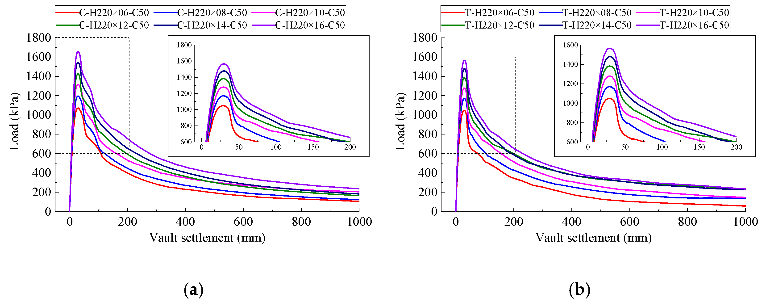
The load-vault settlement curves of CFST circular arc arch members with different section heights are shown in
Figure 8, and the variation curves of performance indexes of each member with section height of steel tube are shown in
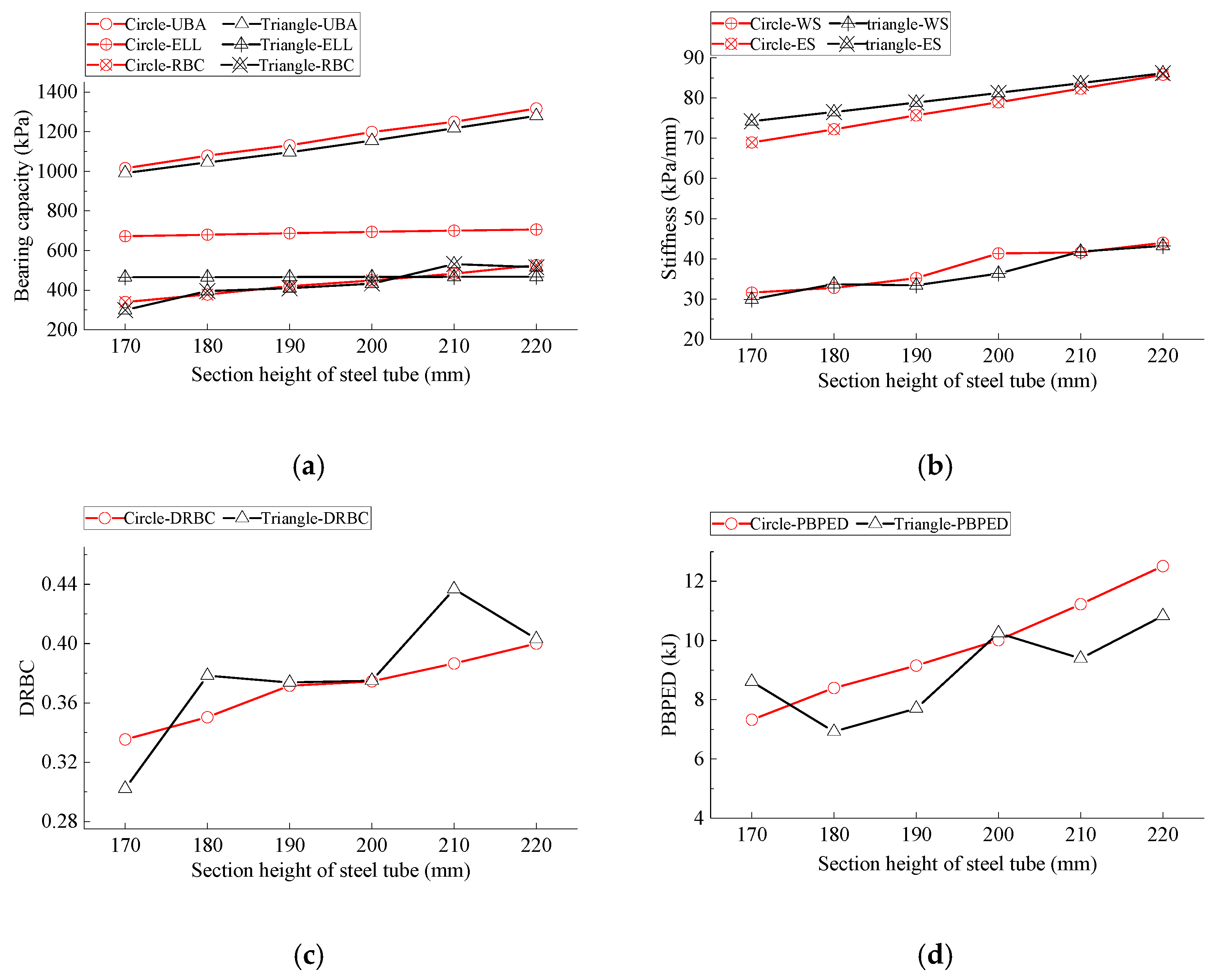
Figure 9.
- (1)
The load-vault settlement curves of CFST members with different section heights of steel tube are similar. The ultimate bearing capacity of each member appears when the vault settlement is about 28 mm, and the bearing capacity decreases obviously after reaching the peak, but it shows good elongation. With the increase of steel tube section height, the ultimate bearing capacity of the member increases steadily, and the post peak ductility also increases slightly.
- (2)
The influence of steel tube section height on the ultimate bearing capacity and residual bearing capacity is obvious, and there is an approximate linear relationship, while the influence on the elastic ultimate load is small. When the section height of CFST increases from 170 mm to 220 mm, the ultimate bearing capacity of circular members increases by 301.42 kPa, with an increase of 29.69%; The residual bearing capacity increased by 186.13 kPa, with an increase of 54.68%; The elastic limit load is increased by 33.75 kPa, with an increase of 5.02%. The ultimate bearing capacity of triangular members is increased by 288.31 kPa, with an increase of 29.11%; The residual bearing capacity increased by 216.23 kPa, with an increase of 72.25%; The elastic limit load is increased by 2.10 kPa, with an increase of 0.45%.
- (3)
The bearing capacity degradation ratio of CFST members increases with the increase of section height. Among them, the circular CFST shows monotonous increase, while the triangular CFST tube fluctuates. However, the bearing capacity degradation ratio of the triangular CFST is higher than that of the circular CFST, indicating that the post buckling performance of the triangular CFST is better than that of the circular CFST.
- (4)
The results show that the elastic stiffness and working stiffness increase with the increase of the section height of the steel tube. The relationship between the elastic stiffness and the section height of the steel tube is approximately linear. The elastic stiffness increment of the circular CFST is about 0.34 kPa·mm−1/mm, and that of the triangular CFST is about 0.24 kPa·mm−1/mm. When the section height of steel tube is small, the overall working stiffness of triangular CFST members is slightly lower than that of circular CFST members with the same section height. With the increase of section height, the difference between them is gradually reduced.
- (5)
The energy dissipation capacity of CFST members increases significantly with the increase of the section height of steel tube. When the section height of the steel tube increases from 170 mm to 220 mm, the plastic deformation energy consumption of the circular member increases from 7.32 kJ to 12.51 kJ, with an increase of 70.90%; The plastic deformation energy consumption of triangular members increased from 8.61 kJ to 10.83 kJ, with an increase of 25.78%. The energy dissipation capacity of circular CFST members is generally higher than that of triangular CFST members at the same section height.
3.2. Analysis of Wall Steel Tube Thickness
The load-vault settlement curves of CFST circular arch members with different steel tube wall thickness are shown in
Figure 10, and the variation curves of performance indexes of each member with steel tube wall thickness are shown in
Figure 11.
- (1)
The wall thickness of steel tube has a significant effect on the ultimate bearing capacity and the post peak bearing capacity decay rate. The larger the steel tube wall thickness is, the higher the peak value of load vault settlement curve is, and the slower the decline rate of the bearing capacity of the member after the peak value is. The decline rate of the bearing capacity of the triangular CFST member is slightly faster than that of the circular CFST member after the peak value is reached.
- (2)
Increasing the wall thickness of the steel tube will significantly improve the ultimate bearing capacity and residual bearing capacity of the member, and slightly increase the elastic ultimate load of the member. When the wall thickness of steel tube increases from 6 mm to 16 mm, the ultimate bearing capacity of circular members increases by 586.47 kPa, with an increase of 54.77%; The residual bearing capacity increased by 360.94 kPa, with an increase of 91.83%; The elastic limit load is increased by 28.06 kPa, with an increase of 4.09%. The ultimate bearing capacity of triangular member is increased by 518.71 kPa, with an increase of 49.51%; The residual bearing capacity increased by 309.22 kPa, with an increase of 90.55%; The elastic limit load is increased by 1.62 kPa, with an increase of 0.35%.
- (3)
The wall thickness of steel tube has a significant effect on the overall stiffness of members. When the wall thickness of the steel tube increases from 6 mm to 16 mm, the elastic stiffness and working stiffness of the circular member increase by 34.15 kPa/mm and 20.9 kPa/mm, respectively, and the increase range is 48.32% and 58.81%, respectively; The elastic stiffness and working stiffness of the triangular member are increased by 28.2 kPa/mm and 17.52 kPa/mm, respectively, and the increase range is 38.14% and 47.99%, respectively. It can be seen that the contribution of the wall thickness of steel tube to the overall stiffness of circular section is greater than that of triangular section.
- (4)
With the increase of the wall thickness of steel tube, the bearing capacity degradation ratio of CFST members increases as a whole, and the performance of circular CFST is the most obvious. The degradation ratio of the bearing capacity of circular CFST members increases slightly when the wall thickness of the steel tube is 6 ~ 8 mm, decreases gradually when the thickness is 8 ~ 14 mm, and increases again when the thickness is 14 ~ 16 mm; When the wall thickness of steel tube is 6 ~ 12 mm, the degradation ratio of bearing capacity of triangular CFST members increases linearly. There is a decline section between 12 ~ 14 mm, and a slight increase again when the thickness is 14 ~ 16 mm. Therefore, sufficient wall thickness of steel tube can maintain a certain bearing capacity after buckling.
- (5)
Since concrete is brittle material, when the CFST members enter the plastic working state, the concrete (especially the concrete in the tension zone) will soon reach the limit of its plastic deformation and failure, so as to withdraw from the work. The steel tube has a strong stiffness and ductility, can withstand greater deformation without damage. Therefore, with the increase of steel tube wall thickness, the energy dissipation capacity of CFST members is significantly improved. When the concrete is partially out of service, the main load-bearing body of the member will shift to the steel tube, and the mechanical performance of the steel tube will significantly affect the energy consumption of the member through plastic deformation before it completely loses its bearing capacity. In general, the energy dissipation capacity of triangular CFST members is significantly lower than that of circular CFST members, and this phenomenon is gradually enlarged with the increasing wall thickness of steel tube.
3.3. Analysis of Core Concrete Grade
The load-vault settlement curves of CFST members with different core concrete grades are shown in
Figure 12, and the performance change curves of each member are shown in
Figure 13.
- (1)
With the improvement of core concrete grade, the peak value of load-vault settlement curve of CFST members increases continuously, but the curve within a certain range before and after the peak value has a higher coincidence degree, and the circular CFST member is more obvious, which indicates that the core concrete grade has less influence on other properties of CFST members except the bearing capacity.
- (2)
The improvement of core concrete grade has more obvious effect on the ultimate bearing capacity of CFST members than the residual bearing capacity and elastic ultimate load, and the improvement effect on the bearing capacity of circular CFST members is also better than that of triangular CFST members. The improvement of core concrete grade has no obvious effect on the overall bearing capacity of CFST members.
- (3)
With the improvement of core concrete grade, the working stiffness and elastic stiffness of CFST members show an upward trend, but the overall change range is small. In terms of working stiffness, circular CFST members are generally higher than triangular CFST members; For the elastic stiffness, when the core concrete grade is lower than C50, the circular CFST member is lower than the triangular CFST member, but with the improvement of the concrete grade, the gap between the two is gradually narrowing. When the concrete grade is higher than C50, the circular CFST member is slightly higher than the triangular CFST member, but the difference is not significant. The influence of concrete grade on the elastic stiffness of CFST members is not obvious. It can be seen that when the core concrete grade reaches a certain degree, the improvement of member stiffness will be very limited by continuously improving the core concrete grade.
- (4)
The influence of core concrete grade on the bearing capacity degradation ratio of CFST members has no obvious regularity, but with the improvement of core concrete grade, circular CFST members mainly show a downward trend, while triangular CFST members mainly show an upward trend. The reason for this phenomenon is that although the high-grade concrete has high strength, its ductility decreases and brittleness increases. When the member buckles, the core concrete with larger curvature will appear tensile stress, which will prompt the high-grade concrete to withdraw from work earlier and reduce the bearing capacity of the member at the post peak stage, and because of the different section form and material parameters, there are some differences in the buckling parts.
- (5)
With the continuous improvement of the core concrete grade, the energy dissipation capacity of circular members gradually increases, but the higher the concrete grade is, the smaller the enhancement amplitude. When the concrete grade is C60, it tends to be stable, even when the concrete grade is C80, there is a downward trend; when the core concrete grade is lower than C70, the concrete grade has little effect on the energy dissipation capacity of triangular members. Only when the core concrete grade is higher than C70, the improvement of concrete grade will significantly increase the energy dissipation capacity of members.
3.4. Analysis of Steel Cross-Sectional Area
Different design parameters, such as steel tube section height, steel tube wall thickness and core concrete grade, affect the bearing capacity of the supporting structure on the one hand and the economic benefit of the supporting structure on the other hand, and the influence of steel tube section height and steel tube wall thickness is more significant. Therefore, the influence of steel tube section parameters on the bearing capacity of concrete filled steel tube members is analyzed from the perspective of steel consumption, as shown in
Figure 14.
- (1)
The results show that there is a general positive correlation between the bearing performance indexes and the steel cross-sectional area of CFST members, and the circular CFST member is the most significant.
- (2)
The slope of the curve affected by the section height of steel tube is obviously larger than that affected by the wall thickness of steel tube, which indicates that the bearing capacity of CFST members is more sensitive to the section height of steel tube.
- (3)
When reaching the same ultimate bearing capacity, the steel cross-sectional area of triangular member is obviously less than that of circular member, which indicates that the steel utilization ratio of triangular CFST support is higher than that of circular CFST support.
4. Conclusions
In this paper, the bearing process of CFST arch frame for tunnel was simulated by finite element analysis software, and the complete process curves from elastic deformation to buckling of 36 research cases were obtained. The three calculation parameters: steel tube section height, steel tube wall thickness and core concrete grade of these cases were different. In order to make statistical analysis for these case curves, the Ultimate Bearing Capacity, Elastic Limit Load, Residual Bearing Capacity, Degradation Ratio of Bearing Capacity, Elastic Stiffness, Working Stiffness and Post Buckling Plastic Energy Dissipation were defined as indicators, then the influence law of the three calculation parameters on the bearing performance of CFST could be comprehensively evaluated by the indicators. The main conclusions are as follows.
The section height of steel tube, the wall thickness of steel tube and the grade of core concrete are positively correlated with the bearing capacity of CFST arch, but the sensitivity of these three factors to the bearing capacity of CFST arch decreases in turn.
With the increase of steel tube cross-section area, the bearing capacity of CFST arch is approximately linear, and the indexes of circular cross-section members are the most significant. It is more economical to improve the bearing capacity of the CFST arch by increasing the height of the steel tube cross-section.
The bearing capacity of CFST arch core concrete depends largely on the restraint of steel tube. The effect of enhancing the bearing capacity of CFST members only by improving the core concrete grade is limited, and when the core concrete grade reaches C50, the strengthening effect is significantly reduced.
5. Discussion
Through numerical simulation, according to the control factor method, the influence of steel pipe section height, steel pipe wall thickness and core concrete grade on the bearing performance of CFST as the supporting structure of traffic tunnel is analyzed in this paper. However, it is worth noting that the calculation model in this paper is based on the conventional simplified assumptions, which is not the case. For example: (1) Tunnel support is not an independent bearing structure. The reinforced anchor connected with the steel frame and the longitudinal connecting members between the steel frame will divide the CFST support into different bearing units. (2) The distribution form of surrounding rock load is not ideal and has strong discreteness. The surrounding rock load used in calculation and analysis is based on the assumption of rock and soil theory. (3) The geometric boundary of the research object is not smooth and uniform, and the structure itself also has the defects of reserved grouting holes, connectors between pipe joints and solid materials. The above factors will affect the buckling shape and bearing performance of CFST supports. The main purpose of this paper is to compare and analyze the influence of CFST material parameters on the bearing performance of steel frames, and these factors have not been deeply studied.
Compared with the single section steel skeleton, a CFST skeleton has significant bearing performance and economic benefits. In order to better promote its application in the supporting structure of traffic tunnel engineering, there are still many design and construction problems worthy of study. For example: (1) Several factors have significant effects on the buckling shape and bearing performance of CFST arch frame, such as surrounding rock load modes, tunnel section shapes, design parameters of CFST members (reinforcing elements, reserved grouting holes, pipe joint connection, etc.), which will be further investigated. (2) The prefabrication and assembly technology of CFST arch frame will be studied in order to improve the overall construction efficiency and reduce the structural defects caused by construction factors.
Author Contributions
Conceptualization, L.L.; Data curation, K.L.; Funding acquisition, L.L.; Investigation, K.L.; Project administration, L.L.; Software, K.L.; Visualization, K.L.; Writing—original draft, L.L.; Writing—review & editing, L.L. All authors have read and agreed to the published version of the manuscript.
Funding
The authors acknowledge the financial support provided by the Fundamental Research Funds for the Central Public Interest Scientific Institutes (Grant No. 2018–9020).
Institutional Review Board Statement
Not applicable.
Informed Consent Statement
Not applicable.
Data Availability Statement
Not applicable.
Conflicts of Interest
The authors declare no conflict of interest.
References
- Han, L.H.; Tao, Z.; Yao, G.H.; Yang, Y.F. Design Calculation of Concrete Filled Steel Tubular Beam-Columns—World Code Comparison (I). Pro. Steel Build. Struct. 2002, 4, 47–55. [Google Scholar] [CrossRef]
- Han, L.H.; Tao, Z.; Yao, G.H.; Yang, Y.F. Design Calculation of Concrete Filled Steel Tubular Beam-Columns—World Code Comparison (II). Pro. Steel Build. Struct. 2002, 4, 53–61. [Google Scholar] [CrossRef]
- Chepurnenko, V.S.; Yazyev, B.M.; Urvachev, P.M.; Avakov, A.A. Determination of stress-strain state of short eccentrically loaded concrete-filled steel tubular (CFST) columns using finite element method with reducing the problem from three-dimensional to two-dimensional. IOP Conf. Ser. Mater. Sci. Eng. 2021, 1083, 012017. [Google Scholar] [CrossRef]
- Li, S.C.; Wang, X.; Wang, Q.; Li, W.T.; Wang, F.Q.; Yang, W.M. Mechanical Property Research and Failure Characteristics of U-Type Confined Concrete Arch in Deep Roadway. Eng. Mech. 2016, 33, 178–187. [Google Scholar] [CrossRef]
- Zhang, X.N.; Shan, R.L.; Zhang, L.; Bai, Y.; Yan, W.; Sun, P.F. Analysis on bending performance of round support stent with concrete filled steel tube in ABAQUS. J. China Coal Soc. 2018, 43, 684–693. [Google Scholar] [CrossRef]
- Mei, Y.C.; Li, W.T.; Yang, N.; Wang, G.; Li, T.C. Failure Mechanism and Optimization of Arch-Bolt Composite Support for Underground Mining Tunnel. Adv. Civ. Eng. 2020, 2020, 5809385. [Google Scholar] [CrossRef] [Green Version]
- Hou, H.T.; Ma, S.; Wang, Q.; Jin, Y.j.; Zhu, W.C.; Chen, L. Experimental Study on Mechanical Behavior of Concrete-Filled Thin-Walled Steel Tube Supported in Tunnel. J. Cent. South Univ. (Sci. Technol.) 2017, 48, 1316–1325. [Google Scholar] [CrossRef]
- Sun, H.B. Study on Stability Bearing Mechanism and Key Technologies of Assembly Confined Concrete Support for Large Section Tunnel. Ph.D. Thesis, Shandong University, Jinan, China, 2019. [Google Scholar]
- Wu, B.; Luo, Y.C.; Zang, J.B. Experimental Study on Mechanical Performance of Tunnel Segment Joints Strengthened Using Concrete-Filled Steel Tubes. J. Build. Struct. 2019, 40, 105–112. [Google Scholar] [CrossRef]
- Luo, Y.C. Experiment and Analysis of Shield Tunnel Strengthened with Concrete Filled Steel Tubes. Ph.D. Thesis, South China University of Technology, Guangzhou, China, 2019. [Google Scholar]
- Wang, Z.C.; Xie, Y.; Xie, Y.L. Analysis of Mechanical Properties of Innovative Support System in Loess Tunnels. Mod. Tunnel. Technol. 2020, 57, 125–135. [Google Scholar] [CrossRef]
- Kong, X.S.; Shan, R.L.; Yuan, H.H.; Xiao, Y.H.; He, X.S.; Bao, T.T. Study on the sustaining effect of concrete-filled steel tubular supports in deep mining roadways. Arab. J. Geosci. 2020, 13, 1092. [Google Scholar] [CrossRef]
- Li, L.; Lei, K. Preliminary Design and Cross-Sectional Form Study of Closed-Type Concrete-Filled Steel Tube Support for Traffic Tunnel. Symmetry 2020, 12, 1368. [Google Scholar] [CrossRef]
- Liu, W.; Xu, M.; Chen, Z.F. Parameters calibration and verification of concrete damage plasticity model of ABAQUS. Ind. Constr. 2014, 44 (Suppl. S1), 167–213. [Google Scholar] [CrossRef]
- GB 50010-2010; Code for Design of Concrete Structures. China Architecture & Building Press: Beijing, China, 2010.
- Li, X.B. Steel Tube Confined Concrete Strength and the Roadway Compression Ring Enhanced Support Theory. Ph.D. Thesis, China University of Mining & Technology, Beijing, China, 2012. [Google Scholar]
- GB 50017-2017; Standard for Design of Steel Structures. China Architecture & Building Press: Beijing, China, 2017.
Figure 1.
Schematic diagram of research object.
Figure 1.
Schematic diagram of research object.
Figure 2.
Calculation model and grid division diagram. (a) Circular section CFST arch; (b) Triangular section CFST arch.
Figure 2.
Calculation model and grid division diagram. (a) Circular section CFST arch; (b) Triangular section CFST arch.
Figure 3.
Uniaxial stress-strain curve of concrete. (a) C30; (b) C40; (c) C50; (d) C60; (e) C70; (f) C80.
Figure 3.
Uniaxial stress-strain curve of concrete. (a) C30; (b) C40; (c) C50; (d) C60; (e) C70; (f) C80.
Figure 4.
Grid size meaning.
Figure 4.
Grid size meaning.
Figure 5.
Load-Vault settlement history curves with different grid density.
Figure 5.
Load-Vault settlement history curves with different grid density.
Figure 6.
Variation curve of ultimate bearing capacity under different grid density.
Figure 6.
Variation curve of ultimate bearing capacity under different grid density.
Figure 7.
Variation curve of vault settlement when reaching the ultimate bearing capacity under different grid density.
Figure 7.
Variation curve of vault settlement when reaching the ultimate bearing capacity under different grid density.
Figure 8.
Load-vault settlement curve of CFST members with different section heights of steel tube. (a) Circular section CFST; (b) Triangular section CFST.
Figure 8.
Load-vault settlement curve of CFST members with different section heights of steel tube. (a) Circular section CFST; (b) Triangular section CFST.
Figure 9.
Performance curve of CFST members with different section heights of steel tube. (a) Change curve of earing capacity; (b) Change curve of stiffness; (c) Change curve of DRBC; (d) Change curve of PBPED.
Figure 9.
Performance curve of CFST members with different section heights of steel tube. (a) Change curve of earing capacity; (b) Change curve of stiffness; (c) Change curve of DRBC; (d) Change curve of PBPED.
Figure 10.
Load-vault settlement curve of CFST members with different wall thickness of steel tube. (a) Circular section CFST; (b) Triangular section CFST.
Figure 10.
Load-vault settlement curve of CFST members with different wall thickness of steel tube. (a) Circular section CFST; (b) Triangular section CFST.
Figure 11.
Performance curve of CFST members with different wall thickness of steel tube. (a) Change curve of earing capacity; (b) Change curve of stiffness; (c) Change curve of DRBC; (d) Change curve of PBPED.
Figure 11.
Performance curve of CFST members with different wall thickness of steel tube. (a) Change curve of earing capacity; (b) Change curve of stiffness; (c) Change curve of DRBC; (d) Change curve of PBPED.
Figure 12.
Load-vault settlement curve of CFST members with different core concrete grades. (a) Circular section CFST; (b) Triangular section CFST.
Figure 12.
Load-vault settlement curve of CFST members with different core concrete grades. (a) Circular section CFST; (b) Triangular section CFST.
Figure 13.
Performance curve of CFST members with different core concrete grades. (a) Change curve of earing capacity; (b) Change curve of stiffness; (c) Change curve of DRBC; (d) Change curve of PBPED.
Figure 13.
Performance curve of CFST members with different core concrete grades. (a) Change curve of earing capacity; (b) Change curve of stiffness; (c) Change curve of DRBC; (d) Change curve of PBPED.
Figure 14.
General distribution of bearing capacity index of components. (a) Ultimate bearing capacity; (b) Working stiffness; (c) Residual bearing capacity; (d) Energy consumption capacity.
Figure 14.
General distribution of bearing capacity index of components. (a) Ultimate bearing capacity; (b) Working stiffness; (c) Residual bearing capacity; (d) Energy consumption capacity.
Table 1.
Design table for comparative study.
Table 1.
Design table for comparative study.
| Section Shape | 1 Research Group on Steel Tube Section Height | 2 Research Group on Steel Tube Wall Thickness | 3 Research Group on Core
Concrete Grade |
|---|
| H/mm | t/mm | C | Code | H/mm | t/mm | C | Code | H/mm | t/mm | C | Code |
|---|
| Circle | 170 | 10 | 50 | C-H170 × 10-C50 | 220 | 6 | 50 | C-H220 × 06-C50 | 220 | 10 | 30 | C-H220 × 10-C30 |
| 180 | C-H180 × 10-C50 | 8 | C-H220 × 08-C50 | 40 | C-H220 × 10-C40 |
| 190 | C-H190 × 10-C50 | 10 | C-H220 × 10-C50 | 50 | C-H220 × 10-C50 |
| 200 | C-H200 × 10-C50 | 12 | C-H220 × 12-C50 | 60 | C-H220 × 10-C60 |
| 210 | C-H210 × 10-C50 | 14 | C-H220 × 14-C50 | 70 | C-H220 × 10-C70 |
| 220 | C-H220 × 10-C50 | 16 | C-H220 × 16-C50 | 80 | C-H220 × 10-C80 |
| Triangle | 170 | 10 | 50 | T-H170 × 10-C50 | 220 | 6 | 50 | T-H220 × 06-C50 | 220 | 10 | 30 | T-H220 × 10-C30 |
| 180 | T-H180 × 10-C50 | 8 | T-H220 × 08-C50 | 40 | T-H220 × 10-C40 |
| 190 | T-H190 × 10-C50 | 10 | T-H220 × 10-C50 | 50 | T-H220 × 10-C50 |
| 200 | T-H200 × 10-C50 | 12 | T-H220 × 12-C50 | 60 | T-H220 × 10-C60 |
| 210 | T-H210 × 10-C50 | 14 | T-H220 × 14-C50 | 70 | T-H220 × 10-C70 |
| 220 | T-H220 × 10-C50 | 16 | T-H220 × 16-C50 | 80 | T-H220 × 10-C80 |
Table 2.
Summary of concrete material parameters.
Table 2.
Summary of concrete material parameters.
| Material Name | E0 (GPa) | ν | ρ (t/m3) | fc,r (MPa) | εc,r (με) | αc | ft,r (MPa) | εt,r (με) | αt | ψ (°) | σb0/σc0 | Kc | κ | ωc | ωt |
|---|
| C30 Concrete | 30.0 | 0.2 | 2.3 | 20.1 | 1471 | 0.746 | 2.01 | 95.24 | 1.264 | 15 | 1.16 | 0.67 | 0.1 | 1 | 0 |
| C40 Concrete | 32.5 | 0.2 | 2.3 | 26.8 | 1589 | 1.168 | 2.39 | 104.36 | 1.796 |
| C50 Concrete | 34.5 | 0.2 | 2.3 | 32.4 | 1678 | 1.499 | 2.64 | 110.1 | 2.191 |
| C60 Concrete | 36.0 | 0.2 | 2.3 | 38.5 | 1769 | 1.853 | 2.85 | 114.7 | 2.552 |
| C70 Concrete | 37.0 | 0.2 | 2.3 | 44.5 | 1844 | 2.183 | 2.99 | 117.8 | 2.793 |
| C80 Concrete | 38.0 | 0.2 | 2.3 | 50.2 | 1922 | 2.490 | 3.11 | 120.2 | 3.032 |
| C30 Shotcrete | 25.0 | 0.2 | 2.2 | 20.1 | 1471 | 0.746 | 2.01 | 95.24 | 1.264 |
Table 3.
Summary of steel material parameters.
Table 3.
Summary of steel material parameters.
| Material Name | ES (GPa) | ν | ρ (t/m3) | fy (MPa) | fu (MPa) |
|---|
| Q235 | 206 | 0.31 | 7.85 | 279 | 450 |
Table 4.
Comparative analysis cases.
Table 4.
Comparative analysis cases.
| No. | Grid Size (mm) | Number of Nodes | Number of Elements |
|---|
| S | SL | T | TL | C1 | C2 | CL |
|---|
| 1 | 30 | 160 | 20 | 100 | 16 | 40 | 80 | 10,970 | 7117 |
| 2 | 28 | 150 | 19 | 95 | 15 | 37 | 75 | 11,554 | 7466 |
| 3 | 26 | 140 | 17 | 85 | 14 | 35 | 70 | 14,783 | 9854 |
| 4 | 24 | 130 | 16 | 80 | 13 | 32 | 65 | 18,239 | 12,337 |
| 5 | 22 | 120 | 15 | 75 | 12 | 30 | 60 | 21,356 | 14,861 |
| 6 | 21 | 110 | 14 | 70 | 11 | 27 | 55 | 26,884 | 19,320 |
| 7 | 19 | 100 | 12 | 60 | 10 | 25 | 50 | 37,798 | 27,990 |
| 8 | 17 | 90 | 11 | 55 | 9 | 22 | 45 | 44,237 | 32,502 |
| 9 | 15 | 80 | 10 | 50 | 8 | 20 | 40 | 61,387 | 46,945 |
| 10 | 13 | 70 | 9 | 45 | 7 | 17 | 35 | 90,661 | 71,808 |
| 11 | 11 | 60 | 8 | 40 | 6 | 15 | 30 | 140,006 | 115,335 |
| 12 | 9 | 50 | 7 | 35 | 5 | 12 | 25 | 234,755 | 200,532 |
| 13 | 7 | 40 | 5 | 25 | 4 | 10 | 20 | 456,567 | 399,348 |
| 14 | 5 | 30 | 4 | 20 | 3 | 8 | 15 | 1,079,513 | 980,260 |
| Publisher’s Note: MDPI stays neutral with regard to jurisdictional claims in published maps and institutional affiliations. |
© 2022 by the authors. Licensee MDPI, Basel, Switzerland. This article is an open access article distributed under the terms and conditions of the Creative Commons Attribution (CC BY) license (https://creativecommons.org/licenses/by/4.0/).


