Article

Wear Characteristics of Cutting Tool in Brittle Removal of a Ductile Meta in High-Speed Machining

1
School of Mechanical & Automotive Engineering, Qilu University of Technology (Shandong Academy of Sciences), Jinan 250353, China
2
School of Mechanical Engineering, Shandong University, Jinan 250061, China
*
Author to whom correspondence should be addressed.
Symmetry 2021, 13(9), 1679; https://doi.org/10.3390/sym13091679
Submission received: 10 August 2021 / Revised: 1 September 2021 / Accepted: 6 September 2021 / Published: 12 September 2021
(This article belongs to the Section Engineering and Materials)

Abstract

:
The contact stress and heating effect between the cutting tool and workpiece in metal machining is symmetrical. However, the symmetry may be destroyed by changes in the workpiece material mechanical properties, such as ductility. The goal of this study is to reveal the wear characteristics of the cutting tool in machining a ductile metal with the cutting speed at which the metal is embrittled by the high-strain-rate-embrittle effect (HSREE). Orthogonal high-speed turning experiments were carried out. Pure iron type DT8 was cut at different cutting speeds, ranging from 1000 m/min to 9000 m/min. The shape and morphology of the chips obtained in the experiment were observed and analyzed by optical microscope and scanning electron microscope (SEM). Tool wear characteristics at different cutting speeds were observed. It shows that the pure iron becomes completely brittle when the cutting speed is higher than 8000 m/min. On the rake face, the coating of the cutting tool bursts apart and peels off. A matrix crack originates in the cutting edge or rake face and extends to the flank face of the cutting tool. The effects of HSREE on the tool wear is discussed. The findings of this study are helpful for choosing a suitable tool for brittle cutting of the ductile metal pure iron with very high cutting speed and solving the problems in machining due to its high ductility and high stickiness.

1. Introduction

High-speed machining (HSM) has advantages of low cutting force and cutting heat, so HSM can reduce the stress and thermal deformation of a workpiece and improve the machining accuracy of the workpiece. HSM also has high material removal rate and resultant high machining efficiency. In some cases, HSM can replace grinding in the fabrication of components with hardened matrix and then simplify the manufacturing process of the components [1].
The strain rate in the deformation zone in HSM is very high, and may reach a level of 106–107 s−1. The high strain rate may lead to great changes in the mechanical properties of a workpiece material. It is known that the yield strength and flow strength of a material increases with the increase in deformation rate [2,3]. For many materials, the strengths sharply increase when the strain rate in the deformation zone exceeds 103–104 s−1 [4,5]. With the changes in strengths, the plasticity (ductility) of a material may also change in almost the same strain rate range [6,7,8]. It is found that the ductility (failure strain) of the material decreases rapidly when the strain rate is above about 104 s−1, which can be called HSREE.
The HSREE has been found in many metals, such as steels [6,7,8], titanium alloys [9,10], and other metallic materials [11]. In 1994, Klepaczko carried out a series of experiments with different impact velocities by a double notch shear equipment on the low-alloy steel XC 18 (French standards) and VAR4340. He found that there is a critical impact velocity at which the failure strain begins to decrease rapidly with further increases in impact velocity. The strain rate corresponding to the critical impact velocity is approximately 104.5 s−1 for the two steels [6]. Yu [7] also found a similar phenomenon in the pure shear experiment of the hat-shaped specimen of AISI D2 steel. Xu et al. [8] used a new type of double-shear specimen to study the shear failure behavior of 603 steel with the strain rate ranging from 0.001 to 45,000 s−1. The result shows that, with the increase in strain rate, the failure stress increases slightly; while the fracture strain decreases rapidly, the material is more likely to fail brittlely at high strain rates. Zheng et al. [9] and Xu et al. [10] found similar results in the high-strain-rate loading experiment of Ti-6Al-4V alloy; the fracture strain decreases significantly with the increase in strain rate, and the failure mechanism changes from ductile fracture to adiabatic shear band dominated process when the strain rate is higher than approximately 104 s−1. Edwards [11] studied the deformation behavior of metallic materials in the deformation from quasi-static to ultra-high strain rates. The results show that the deformation mechanism of metals has evolved from isothermal deformation at static and quasi-static deformation rates to adiabatic shear bands and twinning at moderate strain rates. Under the ultra-high strain rate, the deformation behavior of the metal turns into fracture phenomena, such as fragmentation and spalling.
As a kind of high ductility material, the HSREE has also been found in pure iron. Rittel et al. [12] studied the mechanical response of pure iron at high strain rates. The results show that, in the strain rate range of 2800–8000 s−1, the fracture strain of the material increases with the increase in the strain rate; obvious strain softening occurs at the strain rate of 8000 s−1; however, the breaking strain of pure iron decreases when the strain rate increases to 10,000 s−1.
HSREE provides a possibility to adopt appropriate cutting parameters to carry out high-performance machining of a material according to the dynamic properties of the material, such as high-speed machining of pure iron in its brittle state by HSREE to avoid the problems incurred by its high ductility and high stickiness in conventional cutting speed [13,14]. However, increasing cutting speed usually accelerates the tool wear of the cutting tool. Increasing friction due to the increase in cutting speed results in high temperature and thermal gradient, which lead to the premature failure of the cutting tool [15,16]. The high temperature also increases the sensitive chemical activity of workpiece materials, leading to severe adhesion, oxidation, and diffusion wear of the cutting tool [17,18].
By now, most research on tool wear focuses on the difficult-to-cut metals with high strength or low thermal properties, and the cutting speed are lower than 4000m/min, which the HSREE do not take on. In this study, cutting experiments on pure iron type DT8 with cutting speeds from 1000 to 9000 m/min are carried out. The focus is put on the wear characteristics of cutting tools in the range of the cutting speed of the HSREE. The shape and morphology of the chips are observed and analyzed by optical microscope and scanning electron microscope (SEM). The tool wear characteristics at different cutting speeds from 1000 to 9000 m/min are observed. The analyses of the tool wear in cutting of pure iron in brittle state may provide a reference for choosing a suitable cutting tool for brittle cutting of pure iron with high cutting speed.

2. Experiments

An as-received pure iron type DT8 was used in the current turning experiments. The chemical compositions and main mechanical and physical properties of the pure iron are listed in Table 1 and Table 2, respectively. The metallographic structure of the pure iron DT8 is shown in Figure 1a. In order to obtain high cutting speeds, a circular disc of pure iron with a diameter of 400 mm and a thickness of 1.5 mm was used in the turning experiments (Figure 1b,c). The disc was obtained from the as-received 1.5 mm thickness cold-rolled iron sheet by laser cutting and was fixed on a clamp with four bolts (Figure 1c). The clamp was installed on the spindle of a CNC machining center type Daewoo mynx530 (Figure 1d,e). A chip collection device was used to enclose the workpiece, the spindle, and the cutting tool to prevent the chips flying out for the chip collection.
Cemented carbide inserts type TCMT16T308, grade YBC252, with TiCN+Al2O3 coatings were used in the turning experiment. Figure 1f shows the clamping position of the insert and the relative position of the insert and the workpiece. The cutting parameters used in the turning experiments are listed in Table 3. In order to minimize the impact of tool wear on chip formation, the cutting length was limited to three circles (approximately 4 m) of the workpiece, after which a new insert was used. Optical microscope type KEYENCE VHX-2000 and SEM type ZEISS SUPRA55 were used for observation and analysis of the chips, cutting tools, and machined surfaces in the turning experiment.

3. Results and Discussions

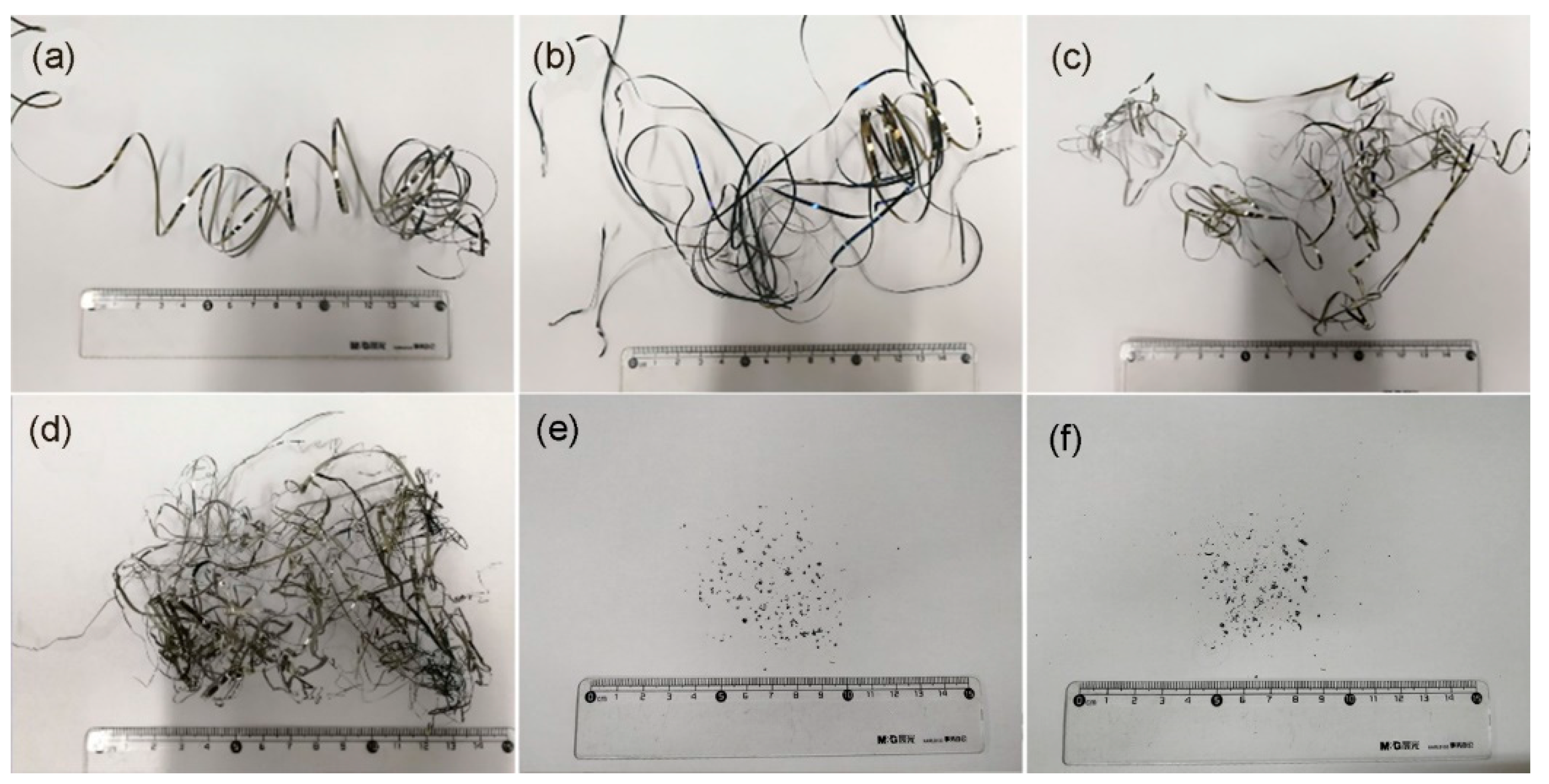
3.1. Chip Shape Evolution and Embrittlement
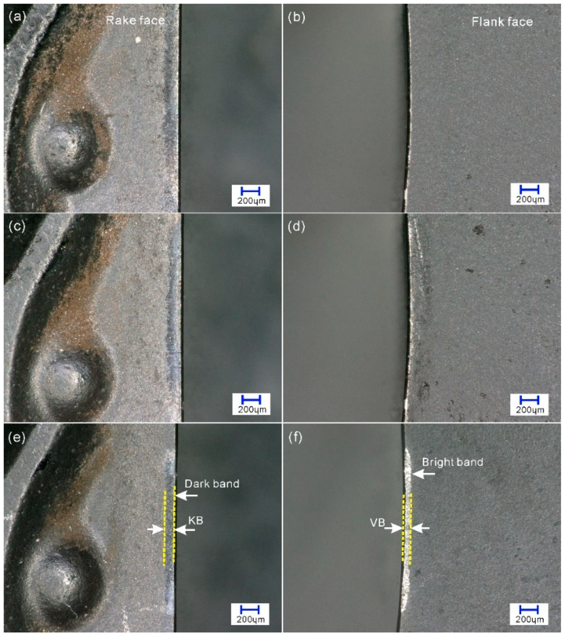
Figure 2a–f show the chip shapes with the increase in cutting speed in the turning experiments. It can be seen that, in the range of cutting speed from 1000 to 7000 m/min, the chip shape is a continuous ribbon (Figure 2a–d), but when the cutting speed reaches 8000 and 9000 m/min, the chip shape turns into small grains with the size of 300–1000 µm.
In the cutting speed range of ribbon chips, there is little difference between the chip shapes at 1000 m/min and those at 3000 m/min macroscopically, but the chips at 5000 and 7000 m/min become much slenderer than those at 1000 and 3000 m/min, which are easier to intertwine. Figure 3 shows that the thickness of the chip decreases with the increase of cutting speed; when the cutting speed is higher than 5000 m/min, the thickness of the chip decreases rapidly.
The higher magnification photograph of the chips in Figure 2e,f are shown in Figure 4; the chips shown in Figure 4a–d are obtained at cutting speeds of 8000 m/min, and those in Figure 4e–i are obtained at 9000 m/min. It shows that the grain chips in Figure 2e,f are tiny flakes, fragments, or molten balls of the removed workpiece material, 300–1000 µm in size. At a cutting speed of 8000 m/min, the main types of the chip shape are molten balls (Figure 4b), irregular molten agglomerates (Figure 4c), and flakes (Figure 4d). According to [19], the molten balls of the chips in the cutting experiment are molten due to the high heat released from the oxidation of the chips when they are heated by the cutting heat and fly into the air. The flake chips shown in Figure 4d have sharp boundaries, indicating that the flake chips are formed by brittle fracture. The color of the flake chips is bright silver, indicating that the chips are formed at a low temperature without high temperature oxidation. The chips at 9000 m/min are similar to those at 8000 m/min, but the molten balls and irregular molten agglomerates seems smaller (Figure 4g). Figure 4f shows that the chip has not only a clear fracture boundary but also delamination fractures. Figure 4h shows an agglomerate like that in Figure 4b, but the melting degree seems lesser. Figure 4i shows a neat brittlely fractured chip similar to that in Figure 4d. These results indicate that the embrittlement of the chip material of the pure iron occurs when the cutting speed reaches 8000 m/min.

3.2. Tool Wear

Figure 5 shows the wear of the rake face and flank of the cutting tool as the cutting speed increases. It can be seen that, under the macroscopic observation, there is a dark band with a width of approximately 100–150 μm on the rake face and a bright band on the flank face of the cutting tool at each cutting speed. With the increase in cutting speed, the width of the dark band (KB) on the rake face becomes slightly narrower, while the bright band becomes more prominent.
The dark bands are the wear marks on the rake face of the cutting tool. Figure 6a shows that the dark band consists of two portions: one is crater wear area; the other is chip adhesion area. In the crater wear area, the surface looks like the initial surface of the cutting tool, and no visible crater can be found in the area, which means that the crater wear in the rake face is slight in the cutting length of approximately 4000 mm with a cutting speed of 1000 m/min. In the adhesion area, there is a thin layer of workpiece material that sticks on the surface of the cutting tool.
There are two possibilities for the bright bands in the flanks: one is that the bright band is the workpiece material bonded to the cutting tool, which usually occurs at a lower cutting speed; the other is that the bright band is the newly worn area in the flank, which is more likely to occur at a higher cutting speed. The tool flank at 4000 m/min is further observed, as shown in Figure 6b. It can be seen from the figure that most of the portion of the bright band on the flank face is flat, just as a soft material is smoothed on the flank face. In the other area, grooves along the cutting direction can be seen, indicating that abrasive wear has occurred in these areas by the hard particles from the workpiece. The result of energy spectrum analysis for the material at point A in Figure 6 is shown in Figure 7. It can be seen from Figure 7 that the adhered material is mainly composed of iron rather than the insert composition elements, such as tungsten, carbon, nitrogen, etc., which indicates that the material adhered on the flank face is from the workpiece. Figure 6 and Figure 7 show that the abrasive wear that occurred on the flank face is slight when the cutting speed is 4000 m/min.
Figure 8 shows the typical wear morphology of the flank at 8000 m/min. There are many parallel grooves on the worn surface of the flank of the cutting tool. These grooves are ploughed by the hard parties from the workpiece material [20], meaning severe abrasive wear takes place in the cutting process at cutting speed of 8000 m/min. In the abrased zone, there are a large number of tiny molten balls. On the outside of the abrased zone, there are large drops of melted chips, indicating that the temperature in the tool–workpiece contact zone has, at some point, reached the melting point of pure iron (1538 ℃). The black color of the adhered melted chips means that the oxide Fe3O4 of the workpiece material has been produced, which easily happens when a tiny piece of iron is heated in the air [21].
The average wear width of the flank VB is shown in Figure 9. It can be seen from the figure that the wear of the flank is intensified with the increase in the cutting speed. A sharp increase in the wear occurs when the cutting speed is higher than 4000 m/min. In the cutting length in the current cutting experiment, there is almost no wear in the flank face at 1000 m/min. The wear width VB is approximately 20 μm at 4000 m/min, while at 8000 and 9000 m/min, the average wear width VB reaches approximately 70 μm.
The tool rake faces at 4000 and 8000 m/min were further observed under SEM (Figure 10). It can be seen from Figure 10 that there are some adhered chips but there is no obvious wear on the rake face of the insert at 4000 m/min. On close observation, the figure in the upper right corner of Figure 10a shows there is a crack in the rake face. At 9000 m/min, obvious cracks were found in the rake face, while there no similar cracks in the flank face except the worn surface caused by abrasive wear.
Further observation of the cracks in the rake face of cutting tool at 8000 m/min is shown in Figure 11. It shows that the cracks occurred at a distance from the cutting edge and look short and reticulate on the rake face of the insert. There are no such types of cracks within the range of 200 μm from the cutting edge. All this indicates that the cracks have only occurred in the coating of the insert. Within the range of 200 μm from the cutting edge, the coating was worn out and a relatively thick and long fracture is found in the matrix.

3.3. Discussion

In the cutting speed range of ribbon chips, the highest temperature is generally caused in the first deformation zone or the second deformation zone of the deformation zones in cutting [22]. With the increase in cutting speed, the tool–workpiece contact temperature increases monotonously [23,24]. In the cutting speed range of the grain chip, the workpiece material is completely brittle. The chip material leaves the cutting zones without plastic deformation. Therefore, the temperature in the first deformation zone and second deformation zone (tool–chip contact zone) is low (Figure 12a) [23], while the high cutting speed makes the temperature in the third deformation zone (tool–workpiece contact zone) very high, even to the melting point of the workpiece material. Some of the broken and fallen chips at the rake face may be squeezed through the tool–workpiece contact zone under the guidance of the machined surface and be instantly heated to a high temperature, which causes the chips to be oxidized or melted into small molten balls (Figure 12b).
With the cutting speed of 8000 m/min, the period of the cutting state, from cutting into the workpiece to a stable cutting, is very short (approximately 0.005 s), during which the contact temperature between cutting tool and machined surface of the workpiece increases from 20 ℃ to approximately the melting point of the workpiece (1538 ℃). This will inevitably lead to a high temperature gradient and a consequent thermal expansion difference in the ambient zones of the tool–workpiece contact zone (Figure 12c). The instantaneous high temperature destroys the heating symmetry in the cutting tool–workpiece contact zone. An expansion zone with compressive stress is formed in the center of the tool–workpiece contact zone, and a tensile stress zone is formed around the center of the tool–workpiece contact zone, including the adjacent rake face. When the temperature gradient and thermal expansion difference are high enough, cracking of the rake face coating or even the matrix of the workpiece will initiate (Figure 12c,d). Moreover, due to the low structural strength of the cutting edge, the cracking is easily started in the rake face side of the cutting edge and then transmitted to the rake face. This is can by validated by the matrix crack shown in Figure 13. It shows that the cracks in the matrix are perpendicular to the cutting edge, extending from the rake face to the flank face. The portion of the crack in the rake face is wider than the portion in the flank face, indicating that the crack originated in the rake face and then propagated to the flank face.

4. Conclusions

The purpose of this paper is to find the wear characteristics of cutting tools in HSM of a ductile metal pure iron DT8 in embrittled state by the high-strain-rate-embrittled effect. Orthogonal turning experiments of the metal at cutting speed 1000 m/min to 9000 m/min were carried out. The chips yielded in the machining experiment were observed, and the tool wear when cutting pure iron in brittle state is analyzed. The main points of the current study can be concluded as follows:
(1)
Pure iron chips are of ribbon chips in a wide cutting speed range from 1000 to 7000 m/min. The thickness of ribbon chips decreases significantly from approximately 0.198 mm to approximately 0.118 mm with the increase in cutting speed from 1000 to 7000 m/min. When the cutting speed reaches 8000 m/min, the chips turn into grain chips, showing that the pure iron becomes completely brittle at a cutting speed of 8000 m/min.
(2)
With the cutting length of 3768 mm, there is almost no wear in the flank face at 1000 m/min. At 4000 m/min, the value of the average wear width VB is approximately 20 μm, while at 8000 and 9000 m/min, the average wear width VB reaches about 70 μm. The brittle removal of the uncut chip makes the tool–workpiece contact zone be the sole heat source in the cutting. Matrix and coating cracking takes place at cutting speed of 8000 m/min, which may be due to the high temperature gradient.
(3)
The findings of this study are helpful for choosing suitable tools and cutting parameters for the brittle cutting of the ductile metal pure iron with very high cutting speed to solve the problems of machining high ductility metals due to their high ductility and high stickiness.

Author Contributions

Conceptualization, G.S. and Z.L.; methodology, P.Z.; validation, H.Z. and B.W.; formal analysis, B.W.; writing—original draft preparation, Y.W. and Z.H.; writing—review and editing, G.S.; project administration, G.S. All authors have read and agreed to the published version of the manuscript.

Funding

This research was funded by the National Natural Science Foundation of China under Grant (51675289, 52075275) and Key Research and Development Plan of Shandong Province (2018GGX103023).

Institutional Review Board Statement

Not applicable.

Informed Consent Statement

Not applicable.

Data Availability Statement

The data presented in this study are available on request from the corresponding author.

Conflicts of Interest

The authors declare no conflict of interest.

References

  1. Schulz, H.; Moriwaki, T. High-speed machining. CIRP Ann. Manuf. Technol. 1992, 41, 637–643. [Google Scholar] [CrossRef]
  2. Clifton, R. Dynamic plasticity. J. Appl. Mech. 1993, 50, 941–952. [Google Scholar] [CrossRef]
  3. Yang, X.; Zhang, B. Material embrittlement in high strain-rate loading. Int. J. Extrem. Manuf. 2019, 1, 022003. [Google Scholar] [CrossRef]
  4. Zerilli, F.J.; Armstrong, R.W. The effect of dislocation drag on the stress-strain behavior of F.C.C. metals. Acta Metal. Mater. 1992, 40, 1803–1808. [Google Scholar] [CrossRef]
  5. Armstrong, R.W.; Walley, S.M. High strain rate properties of metals and alloys. Int. Mater. Rev. 2008, 53, 105–128. [Google Scholar] [CrossRef]
  6. Klepaczko, J.R. Plastic shearing at high and very high strain rates. J. De Phys. IV 1994, 4, C8-35–C8-40. [Google Scholar] [CrossRef]
  7. Yu, J.; Jiang, F.; Rong, Y. Experimental research on mechanical property size effects of AISI D2 steel. Mater. Sci. Tech. Lond. 2012, 20, 83–88. [Google Scholar]
  8. Xu, Z.; Liu, Y.; Sun, Z.; Hu, H.; Huang, F. On shear failure behaviors of an armor steel over a large range of strain rates. Int. J. Impact Eng. 2018, 118, 24–38. [Google Scholar] [CrossRef]
  9. Zheng, C.; Wang, F.; Cheng, X.; Liu, J.; Fu, K.; Liu, T.; Zhu, Z.; Yang, K.; Peng, M.; Jin, D. Failure mechanisms in ballistic performance of Ti–6Al–4V targets having equiaxed and lamellar microstructures. Int. J. Impact Eng. 2015, 85, 161–169. [Google Scholar] [CrossRef]
  10. Xu, Z.; He, X.; Hu, H.; Tan, P.J.; Liu, Y.; Huang, F. Plastic behavior and failure mechanism of Ti-6Al-4V under quasi-static and dynamic shear loading. Int. J. Impact Eng. 2019, 130, 281–291. [Google Scholar] [CrossRef]
  11. Edwards, M. Properties of metals at high rates of strain. Mater. Sci. Tech. Lond. 2006, 22, 453–462. [Google Scholar] [CrossRef]
  12. Rittel, D.; Ravichandran, G.; Venkert, A. The mechanical response of pure iron at high strain rates under dominant shear. Mat. Sci. Eng. A Struct. 2006, 432, 191–201. [Google Scholar] [CrossRef]
  13. Guo, X.; Li, Y.; Cai, L.; Guo, J.; Guo, D. Effects of tool edge radius on chip formation during the micromachining of pure iron. Int. J. Adv. Manuf. Tech. 2020, 108, 2121–2130. [Google Scholar] [CrossRef]
  14. Yang, Y.; Jin, L.; Zhu, J.; Kong, J.; Li, L. Study on cutting force, cutting temperature and machining residual stress in precision turning of pure iron with different grain sizes. Chin. J. Mech. Eng. En. 2020, 4, 159–167. [Google Scholar] [CrossRef]
  15. Arrazola, P.J.; Garay, A.; Fernandez, E.; Ostolaza, K. Correlation between tool flank wear, force signals and surface integrity when turning bars of Inconel 718 in finishing conditions. Int. J. Mach. Machinabil. Mater. 2014, 15, 84–100. [Google Scholar] [CrossRef]
  16. Wang, B.; Liu, Z.; Cai, Y.; Luo, X.; Xiong, Z. Advancements in material removal mechanism and surface integrity of high speed metal cutting: A review. Int. J. Mach. Tool. Manuf. 2021, 166, 103744. [Google Scholar] [CrossRef]
  17. Hatt, O.; Lomas, Z.; Thomas, M.; Jackson, M. The effect of titanium alloy chemistry on machining induced tool crater wear characteristics. Wear 2018, 408, 200–207. [Google Scholar] [CrossRef]
  18. Fan, Y.; Hao, Z.; Lin, J.; Yu, Z. Material response at tool-chip interface and its effects on tool wear in turning Inconel 718. Mater. Manuf. Process. 2014, 29, 1446–1452. [Google Scholar] [CrossRef]
  19. Su, G.; Guan, Y.; Liu, Z. Microstructure of spherical particles generated in high-speed machining of an alloy steel. Int. J. Mater. Res. 2017, 108, 607–610. [Google Scholar] [CrossRef]
  20. Liu, C.; Wan, M.; Zhang, W.; Yang, Y. Chip formation mechanism of Inconel 718: A review of models and approaches. Chin. J. Mech. Eng. Eng. 2021, 34, 1–16. [Google Scholar]
  21. Dhami, H.S.; Viswanathan, K. On the formation of spherical particles in surface grinding. In International Manufacturing Science and Engineering Conference; American Society of Mechanical Engineers: New York, NY, USA, 2020; Volume 84256, p. V001T05A005. [Google Scholar]
  22. Zhao, J.; Liu, Z. Influences of coating thickness on cutting temperature for dry hard turning Inconel 718 with PVD TiAlN coated carbide tools in initial tool wear stage. J. Manuf. Process. 2020, 56, 1155–1165. [Google Scholar] [CrossRef]
  23. Su, G.; Xiao, X.; Du, J.; Zhang, J.; Zhang, P.; Liu, Z.; Xu, C. On cutting temperatures in high and ultrahigh-speed machining. Int. J. Adv. Manuf. Tech. 2020, 107, 73–83. [Google Scholar] [CrossRef]
  24. Su, G.; Liu, Z. Wear characteristics of nano TiAlN-coated carbide tools in ultra-high speed machining of AerMet100. Wear 2012, 289, 124–131. [Google Scholar] [CrossRef]
Figure 1. Metallographic structure of workpiece (a) and experiment setup (bf).
Symmetry 13 01679 g001
Figure 2. Chip shapes at different cutting speeds: (a) 1000 m/min; (b) 3000 m/min; (c) 5000 m/min; (d) 7000 m/min; (e) 8000 m/min; (f) 9000 m/min.
Symmetry 13 01679 g002
Figure 3. Chip thickness versus cutting speed.
Symmetry 13 01679 g003
Figure 4. Grain chips obtained at cutting speed of 8000 m/min and 9000 m/min: (ad) 8000 m/min; (ei) 9000 m/min.
Symmetry 13 01679 g004
Figure 5. Wear morphologies of cutting tools at different cutting speeds under optical obversion. (a,c,e) are the rake faces of 1000, 4000, and 8000 m/min, respectively; (b,d,f) are the corresponding flank faces.
Symmetry 13 01679 g005
Figure 6. Wear morphology in rake face and flank face of the cutting tool at 4000 m/min. (a) chip adhesion and crater wear in rake face; (b) workpiece adhesion and abrasive wear in flank face.
Symmetry 13 01679 g006
Figure 7. EDS result of the point A in Figure 6.
Symmetry 13 01679 g007
Figure 8. Wear morphology of the flank face at 8000 m/min.
Symmetry 13 01679 g008
Figure 9. The wear width of the flank VB of the cutting tools versus speed.
Symmetry 13 01679 g009
Figure 10. Wear morphology of the cutting tools at different cutting speeds under SEM: (a) 4000 m/min; (b) 8000 m/min.
Symmetry 13 01679 g010
Figure 11. Cracks in the rake face of the cutting tool at cutting speed of 8000 m/min. (a) 30× magnificatio; (b) 200× magnification.
Symmetry 13 01679 g011
Figure 12. Schematic representation of the high-gradient temperature distribution at tool–workpiece contact area and its effect on chip formation and cutting tool crack in HSM. (a) general layout; (b) high temperature point when workpiece is completely brittle; (c) matrix crack initiation and extension in the cutting edge; (d) coating crack formation in the rake face.
Symmetry 13 01679 g012
Figure 13. The matrix crack in the rake face and flank face of the cutting tool at cutting speed of 8000 m/min. (a) matrix crack in the rake face; (b) matrix crack extending to the flank face.
Symmetry 13 01679 g013
Table 1. Chemical compositions of pure iron DT8 (wt%).
ElementCSiMnPSCrNiCuAlTiFe
Content0.0030.0060.0080.0050.0060.0030.0030.010.0080.007Bal.
Table 2. Physical and mechanical properties of pure iron DT8.
Yield Strength
σs (MPa)
Tensile Strength
σb (MPa)
Hardness
(Hv)
Thermal Conductivity
k (W/m K)
Specific Heat
c (J/kg K)
Density
ρ (g/cm3)
Elastic Modulus
E (GPa)
1602729446.524607.86204
Table 3. Cutting parameters.
Cutting Speed
vc (m/min)
Feed Rate
fn (mm/r)
Cutting Length
L (mm)
Rake Angle
α (deg)
Width of Cut
w (mm)
Cutting Fluid
1000, 3000, 5000, 7000, 8000, 90000.1~376801.5Dry cutting
Publisher’s Note: MDPI stays neutral with regard to jurisdictional claims in published maps and institutional affiliations.

