
Dynamic Response Analysis of a Multiple Square Loops-String Dome under Seismic Excitation


Abstract
:1. Introduction
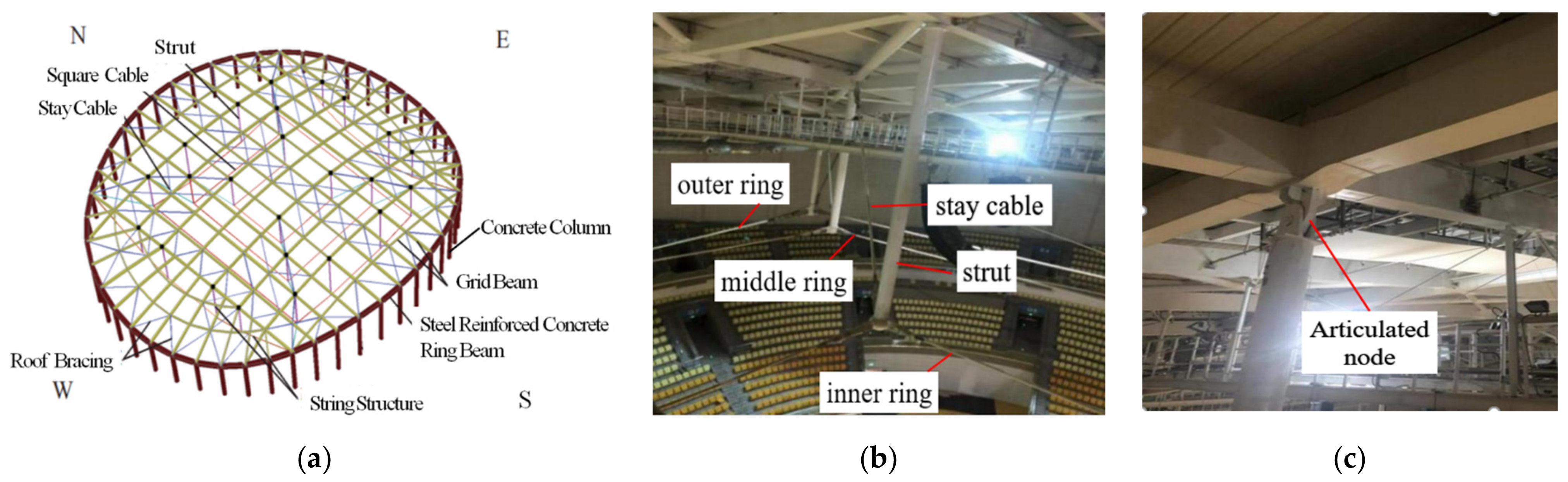
2. Project Overview
3. Numerical Simulation and Model Validation
3.1. Modelling Parameters
3.1.1. Geometric Dimension
3.1.2. Material Characteristics
3.1.3. Finite Element Model Creation
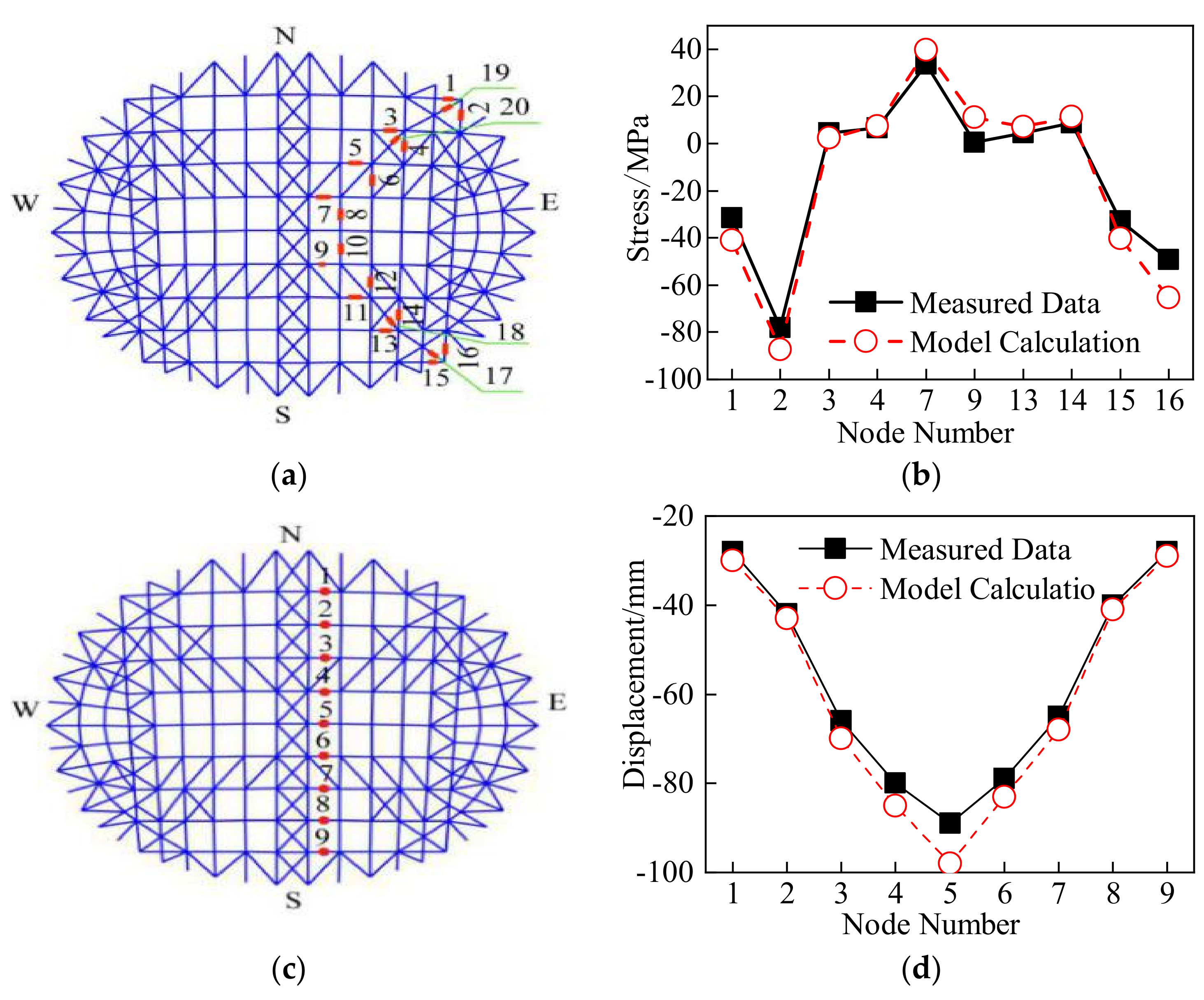
3.2. Model Validation
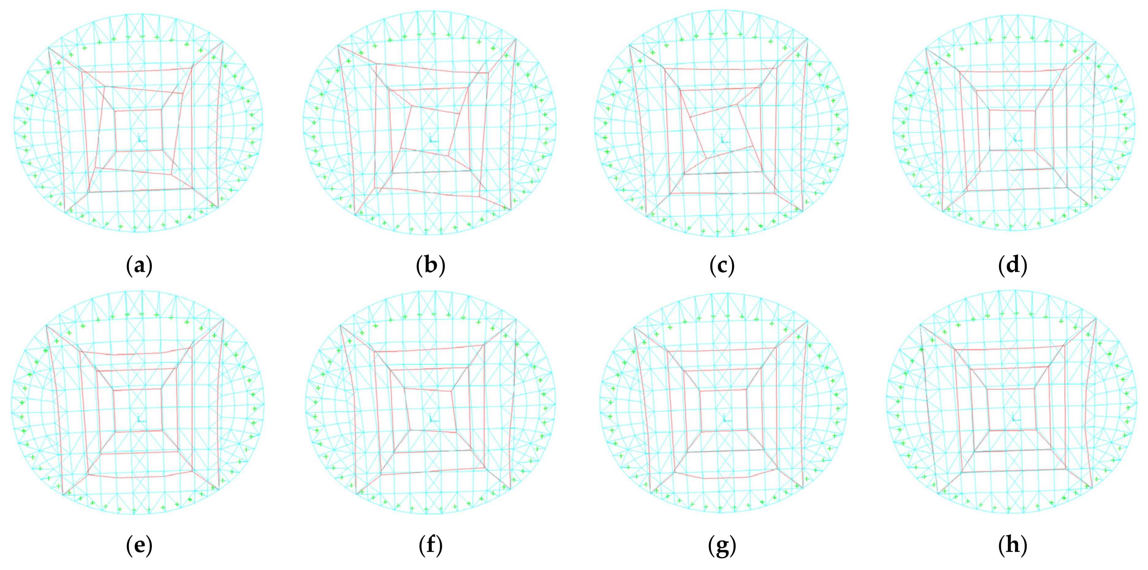
3.3. Structural Dynamic Characteristics
4. Seismic Response Law of Roof Structure under Different Seismic Arrays
4.1. Seismic Arrays Input
4.2. Dynamic Response under the Excitation of No. 1 Seismic Array
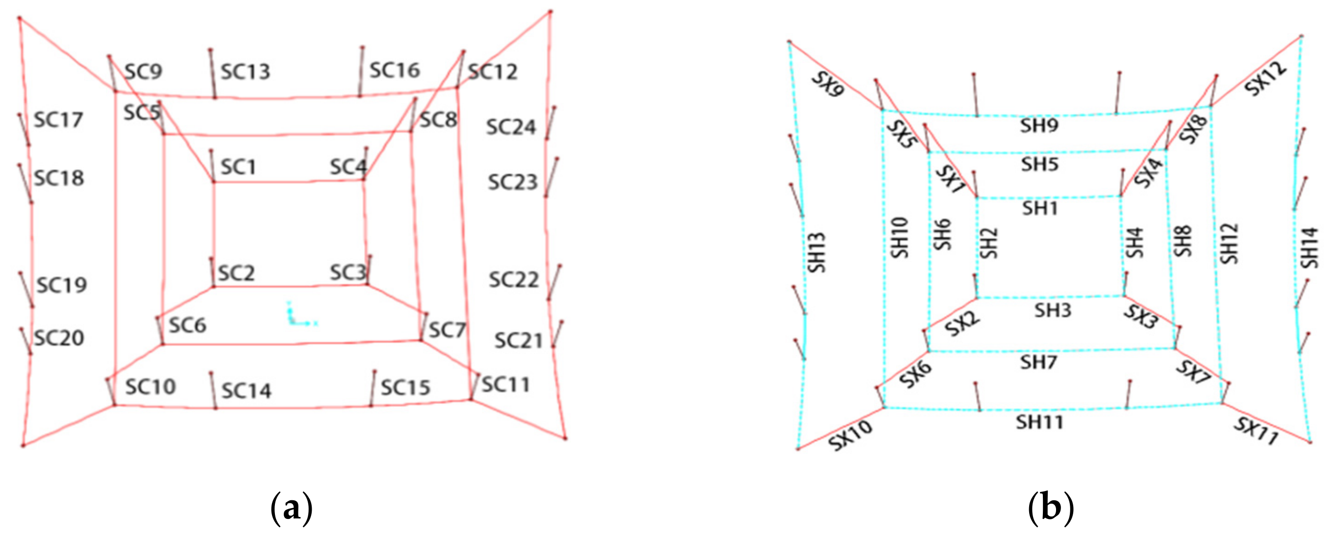
4.2.1. Analysis of the Internal Force Response of Roof Square Ring Cables
4.2.2. Analysis of the Internal Force Response of Roof Grid Beams
4.2.3. Analysis of the Roof Node Deformation
4.3. Dynamic Response under Excitation of No. 2 and No. 3 Seismic Arrays
4.3.1. Analysis on the Internal Force Response of Roof Square Ring Cables
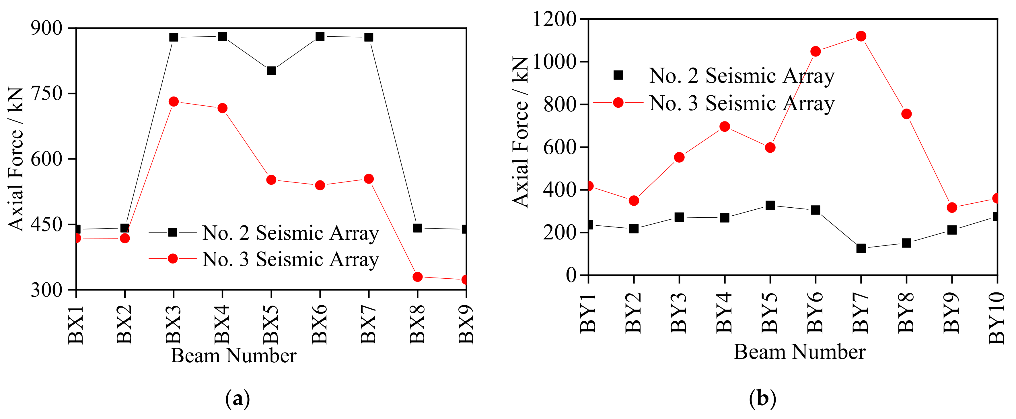
4.3.2. Analysis of the Internal Force Response of Roof Grid Beams
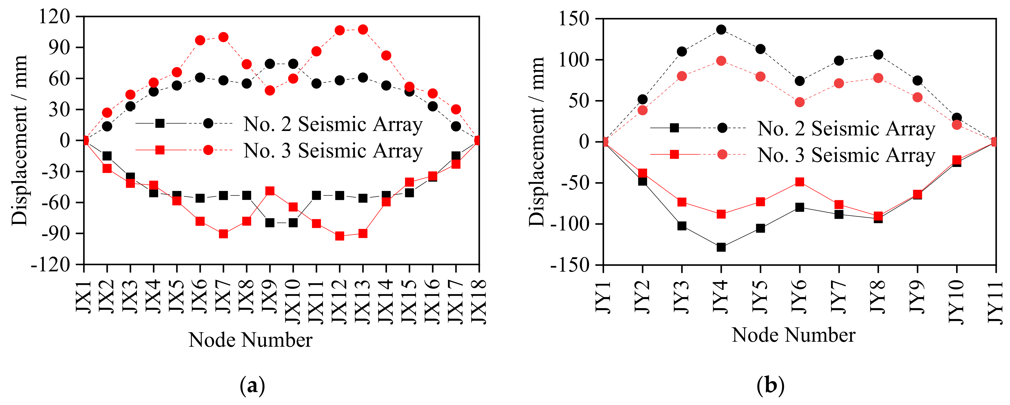
4.3.3. Analysis of the Roof Nodes Deformation
5. Effect Law of Different Types of Ground Motions on the Seismic Response of Roof Structures
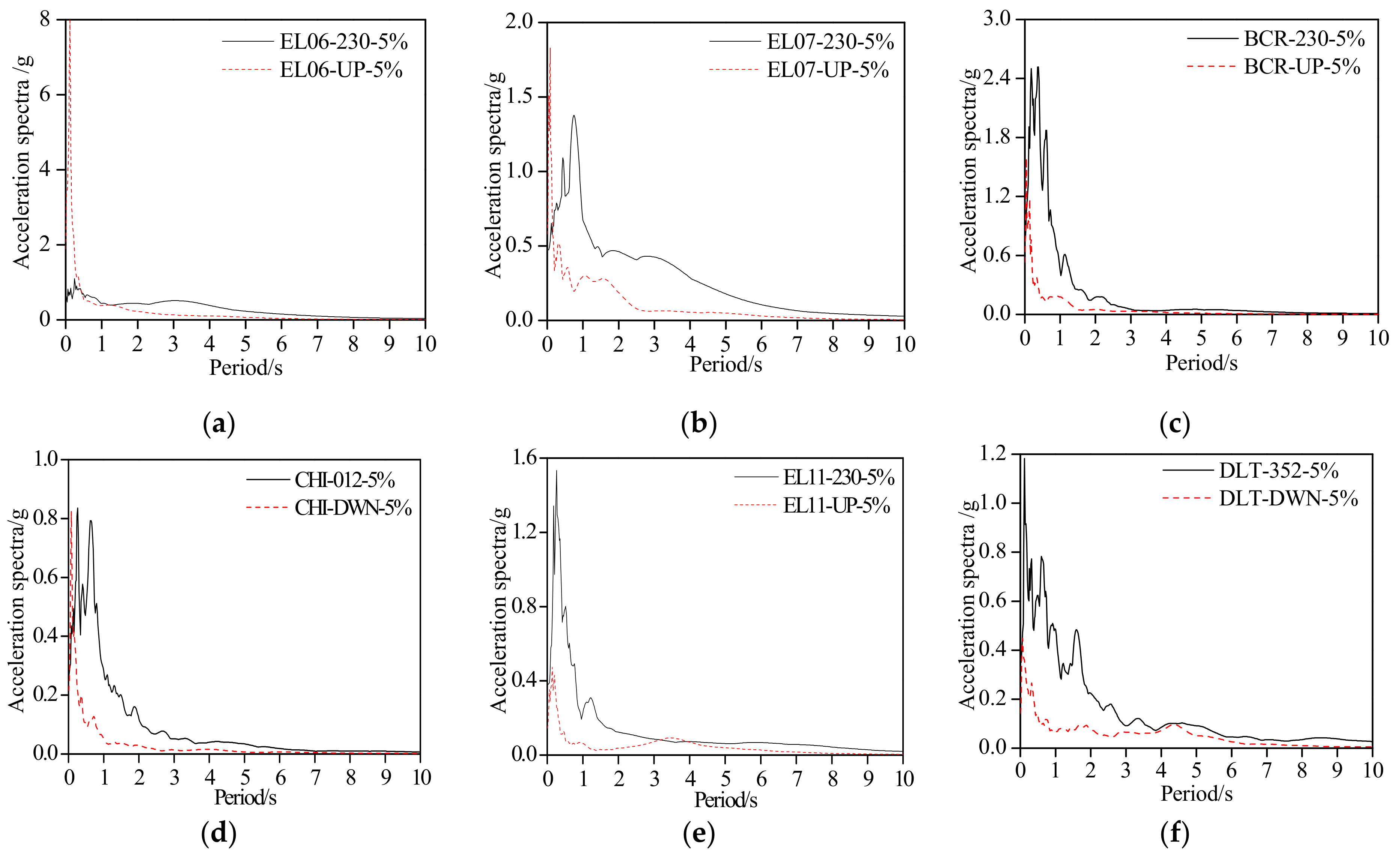
5.1. Input of Different Types of Seismic Waves
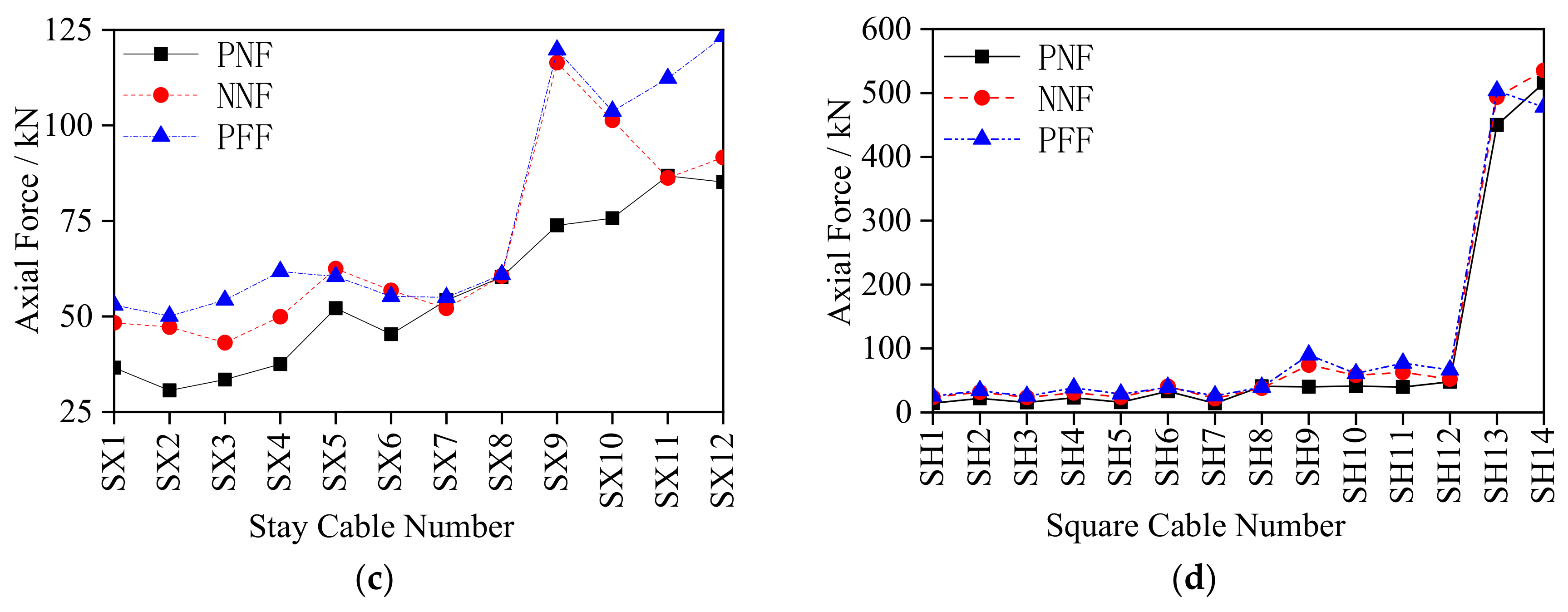
5.2. Analysis of the Internal Force Response of Roof Square Ring Cables
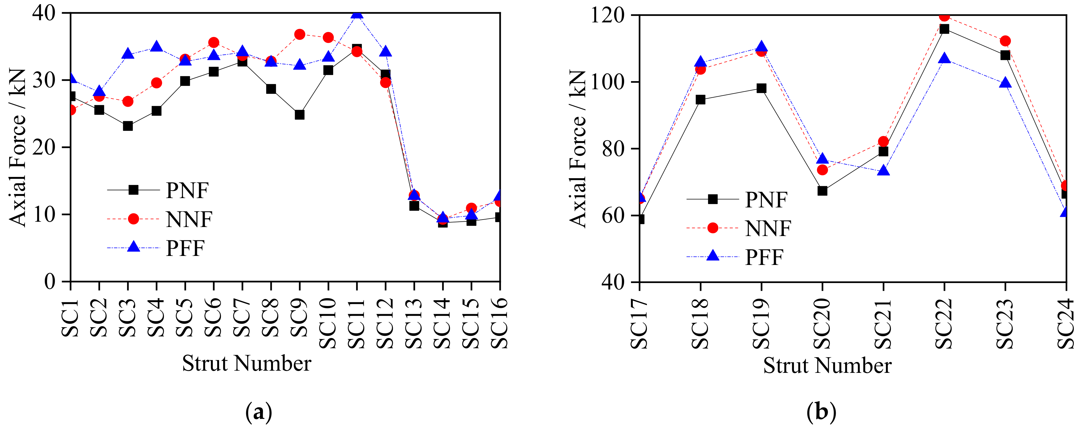
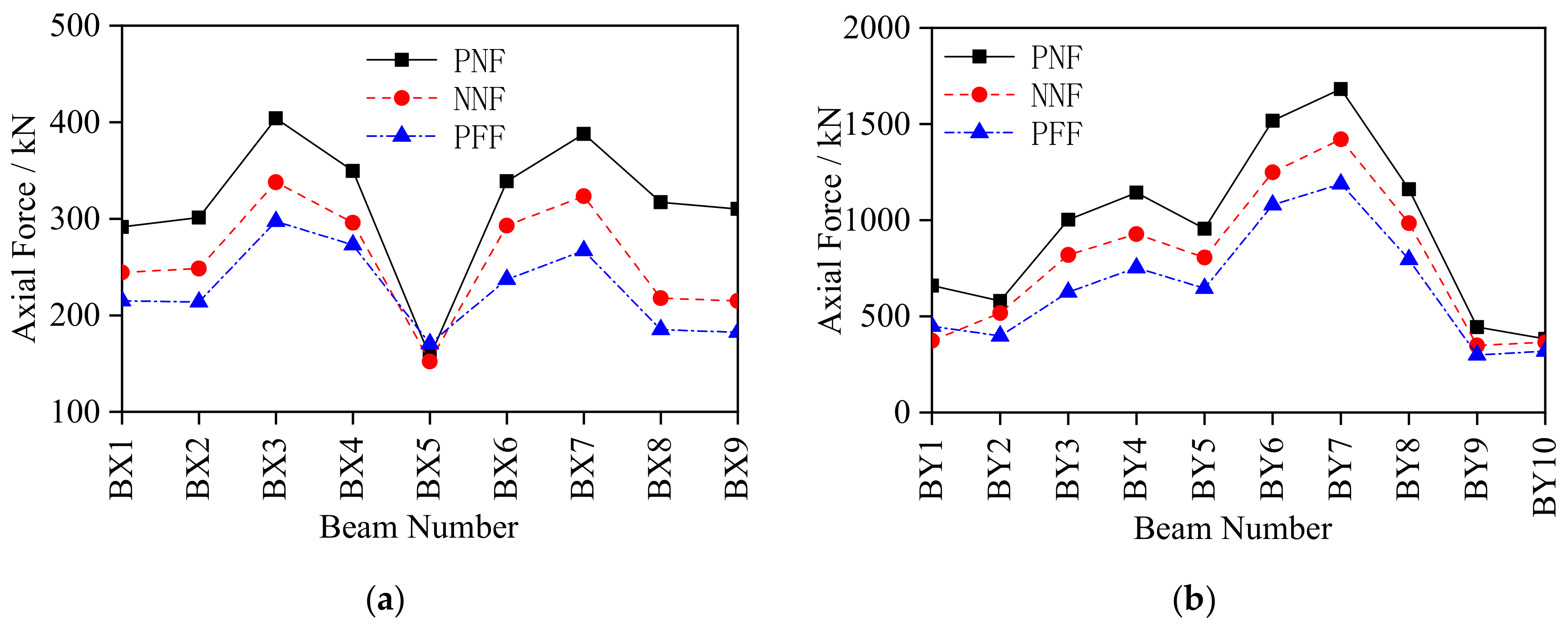
5.3. Analysis of the Internal Force Response of Roof Grid Beams
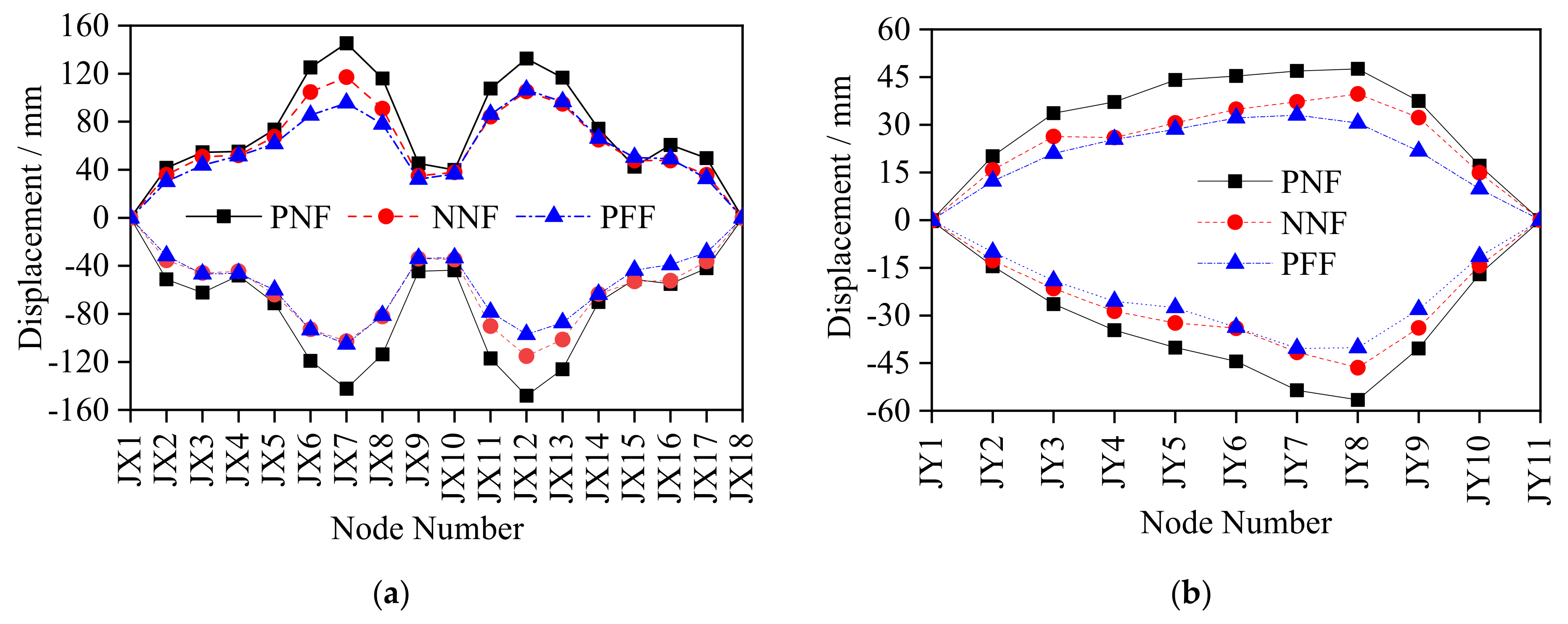
5.4. Analysis of the Roof Nodes Deformation
6. Conclusions and Future Plans
- The natural frequency of the first eight-order vibration modes gradually increased from 0.762 to 1.292, with the main vibration mode being the torsional deformation caused by the cables, while the last five mainly related to the overall roof plane vibration and antisymmetric vibration. Therefore, attention must be paid to the cable vibration of the structure.
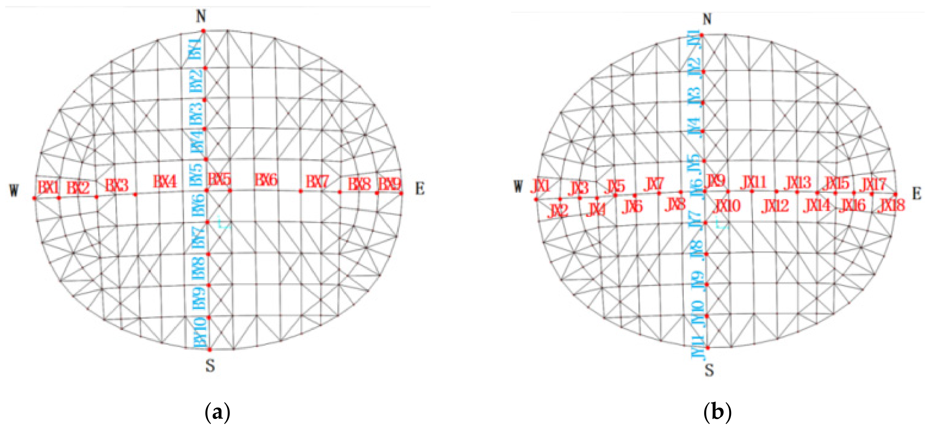
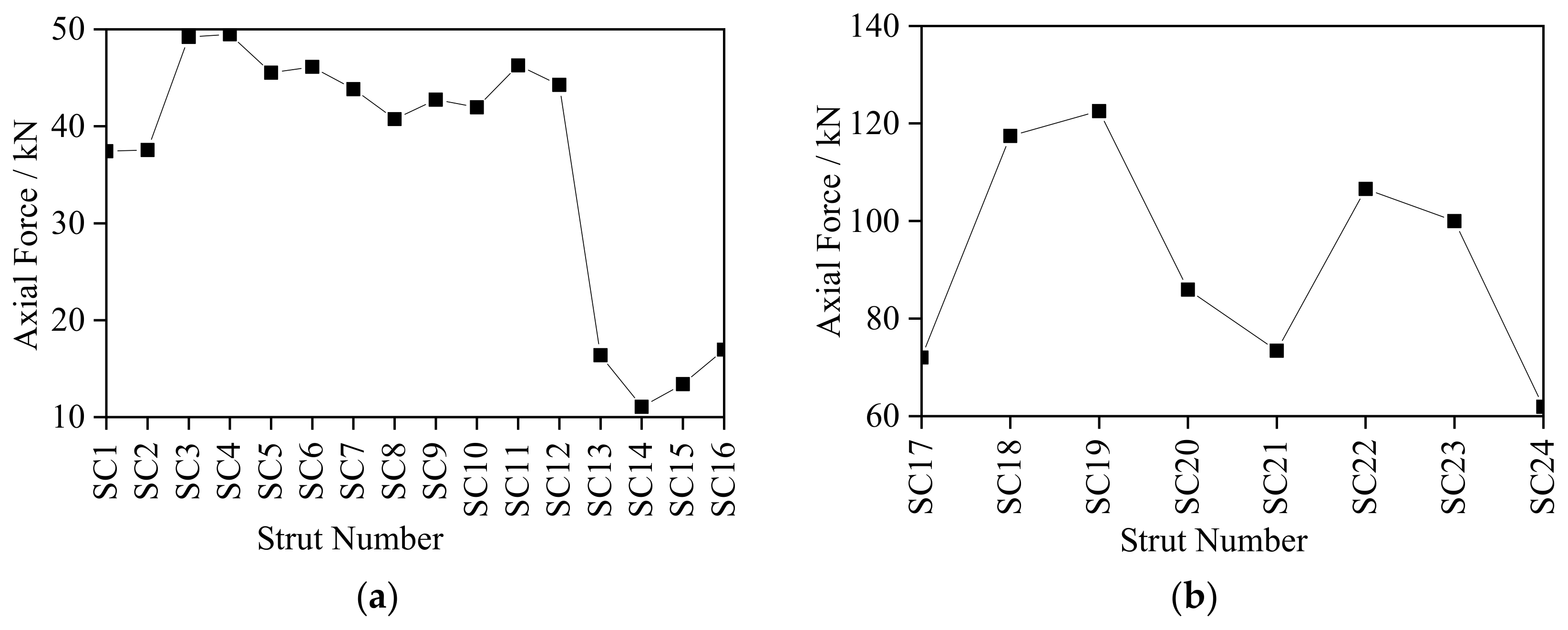
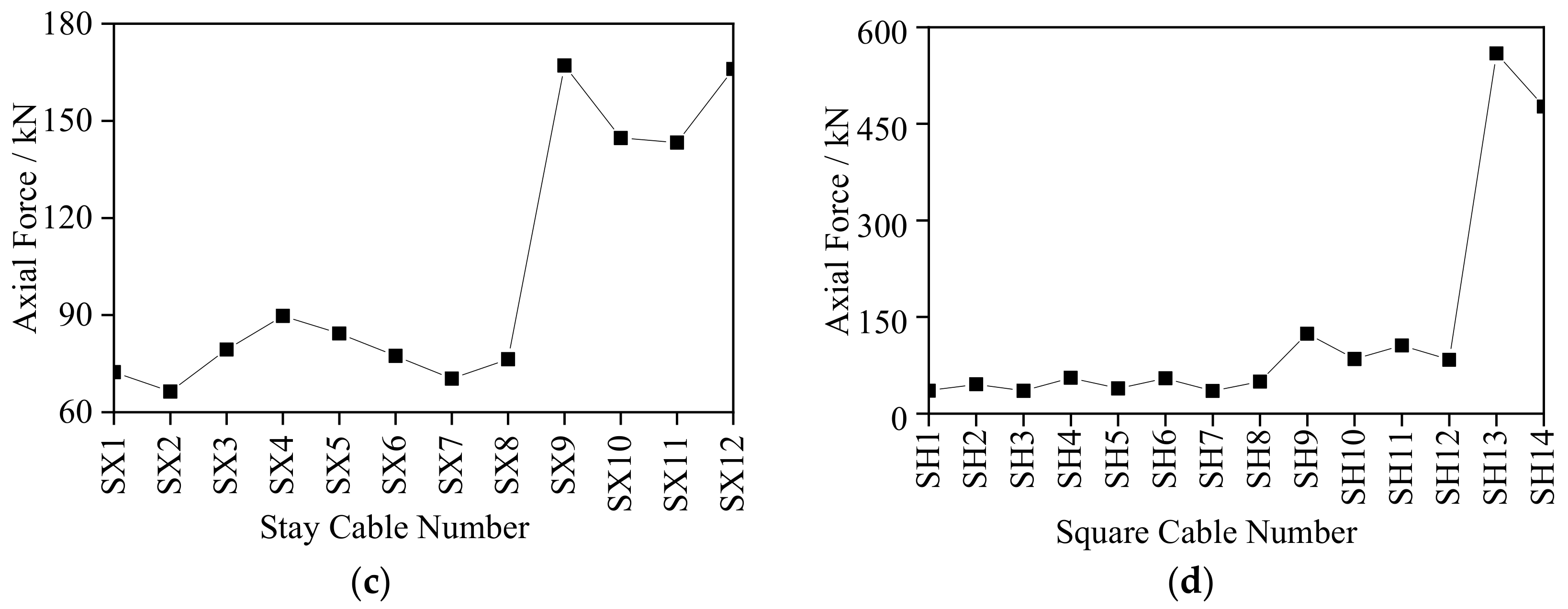
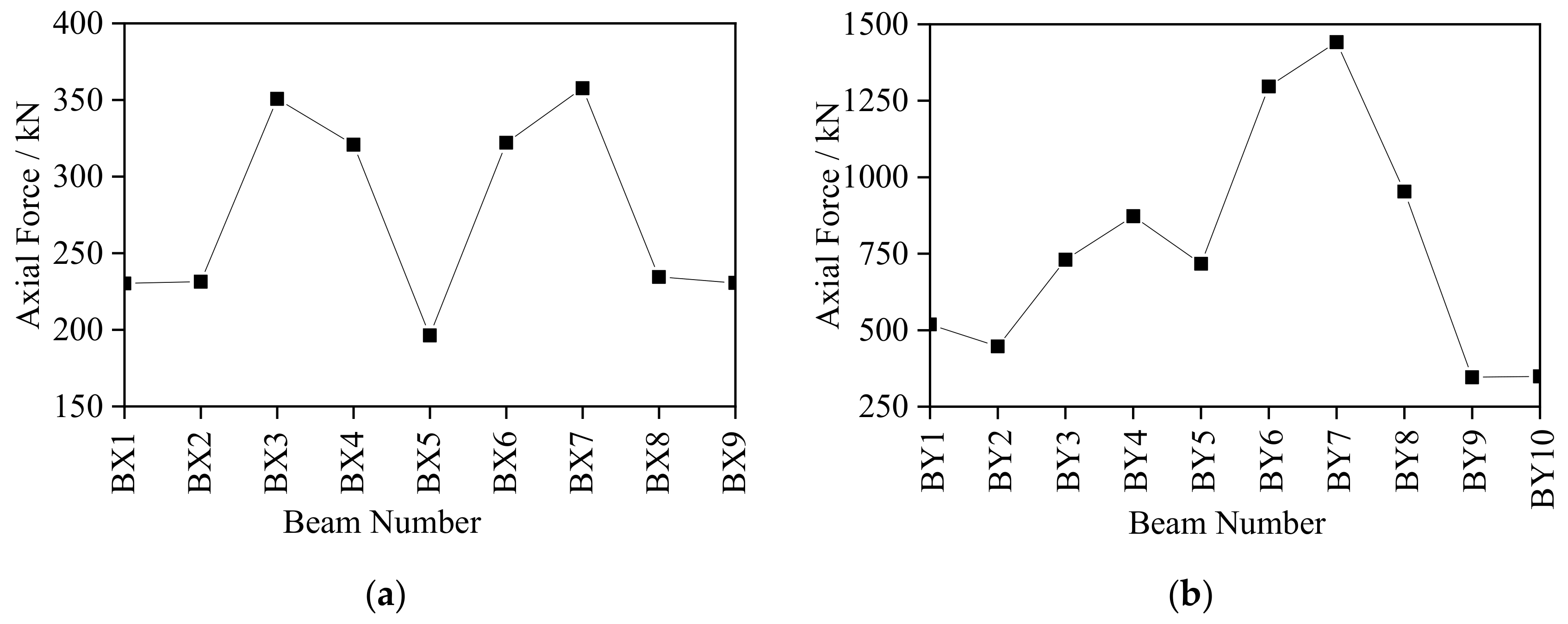
- Under excitation of the No. 1 seismic array, the internal force responses of structural struts, stay cables and ring cables were relatively small. The internal force of the struts of each ring remained equivalent within 50 kN, and weaker than that of the string cables between 60 kN to 125 kN. The largest internal force response of the stay cables was in outer ring between 140 kN to 170 kN, and the internal force of the string cables was the largest between 450 kN to 600 kN. The internal force response of the roof grid beam was symmetrically arranged in the EW direction with the largest internal force response occurring in BX3 and BX7 (about 350 kN). The response in the SN direction was generally larger, among which BY7 had the largest response of 1441.31 kN. The vertical displacement of the grid beam in the EW direction exceeded that in the SN direction. Therefore, emphasis must be laid on monitoring the stress and deformation of the local components of BX3, BX7 and BY7 and the internal force of the string cables.
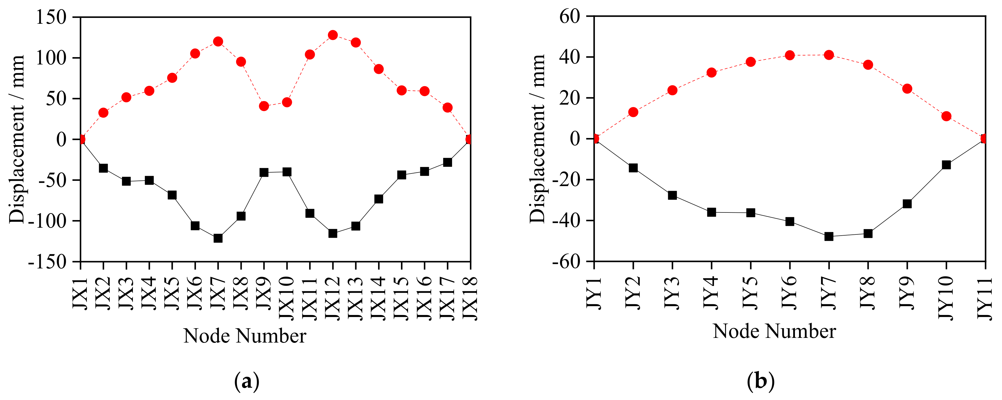
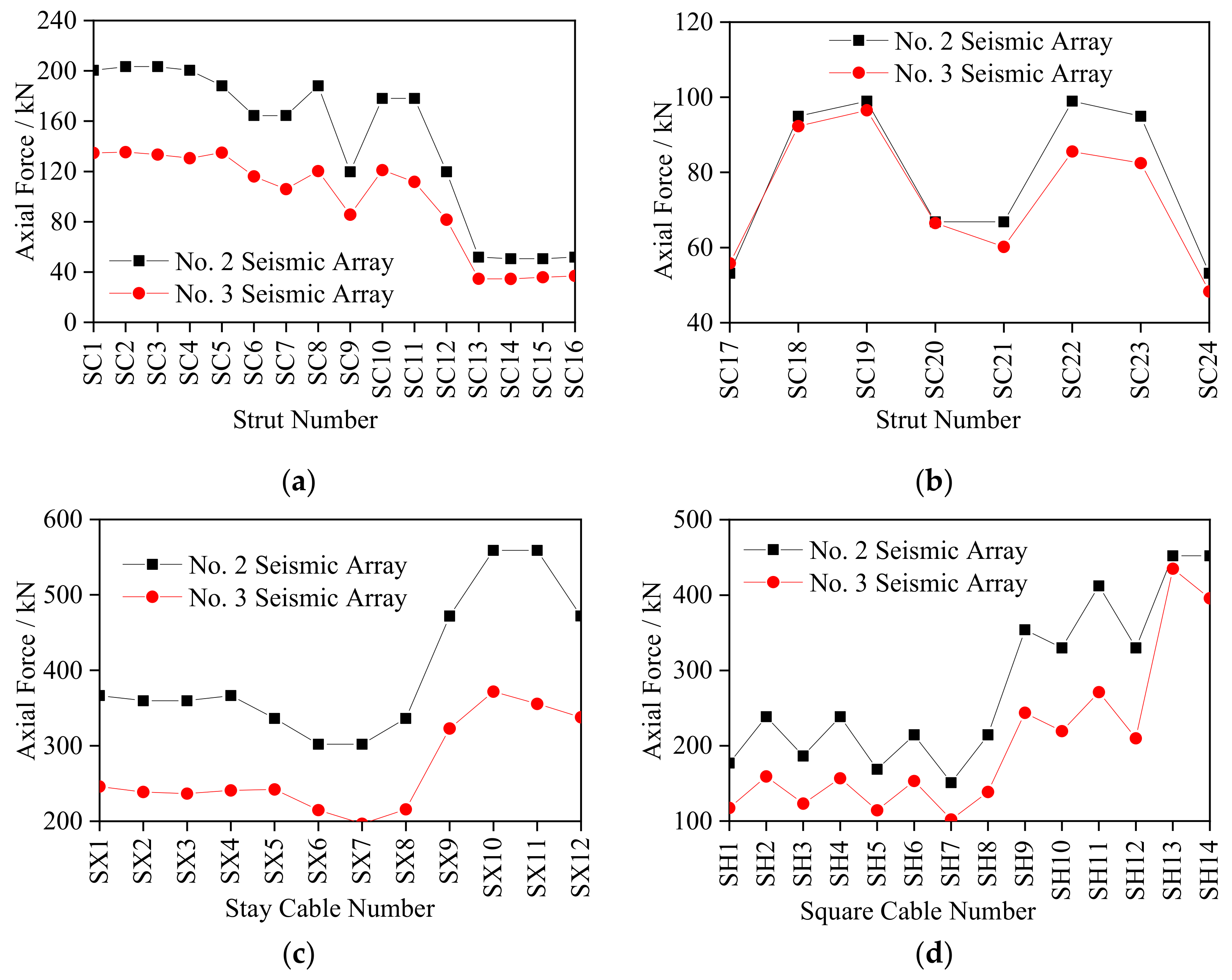
- The structural dynamic response under excitation of No. 2 seismic array was larger than that under the excitation of No. 3 seismic array except for the internal force response of the roof grid beams in the SN direction and the displacement response of the roof grid beam nodes in the EW direction. The internal force response of struts showed a downward trend from the inner ring to the outer ring, with the largest internal force response appearing in stay cables, ring cables and string cables of the outer ring. Under excitation of No. 2 and No. 3 seismic arrays, the internal force response of the struts of each ring was within 200 kN, while the internal force of the outer ring stay cables was the largest with a peak value of 559.71 kN, and the peak value of the internal force of the square cables was 452.22 kN (SH13). The internal force response of the roof grid beam was relatively large, with the peak value in the EW direction of 880.64 kN and in the SN direction of 1119.97 kN. The maximum value of displacement of the grid beam nodes in the SN direction was about twice that in the EW direction, with the largest displacement in node JY4 (136.72 mm). Thus, emphasis must be placed on monitoring the struts in the inner ring and the stay cables, ring cables and string cables in the outer ring, the stress of the roof mid-span grid beam and the deformation of local nodes such as JX7, JX12 and JY4.
- The seismic impulse factor weakened the internal force response of cables and struts. The internal force response of the cables under the seismic excitation in the far field was larger than that in the near field. The seismic impulse increased the internal force response and displacement deformation of the roof grid beam and the seismic excitation in the near field produced greater internal force response and displacement deformation of the grid beam than the far field. The influence of near and far fields exceeded that of the impulse. Thus, attention must be paid to the internal force response and displacement deformation of the roof grid beam when the seismic excitation contains an impulse factor, especially in the near field.
Author Contributions
Funding
Institutional Review Board Statement
Informed Consent Statement
Data Availability Statement
Conflicts of Interest
References
- Chen, Z.H.; Liu, H.B.; Wang, X.D.; Zhou, T. Research Review of String Dome Structure. J. Build. Struct. 2010, 31, 210–215. [Google Scholar]
- Olofin, I.O.; Liu, R.G. Suspen-Dome System: A Fascinating Space Structure. Open Civ. Eng. J. 2017, 11, 131–142. [Google Scholar] [CrossRef]
- Fu, X.Y.; Sun, C.; Wu, B.; Meng, M.L.; Feng, Y.W. New String Structure System Design of Shenzhen South Railway Station Canopy. Build. Struct. 2015, 45, 47–52. [Google Scholar]
- Tuo, M.B.; Wang, Y.; Wu, P.C. Construction Technology of Square Loop-String Structure of Fuzhou Strait Olympic Sports Center Gymnasium. Constr. Technol. 2015, 44, 41–44. [Google Scholar]
- Rao, P.X. Seismic Response and Dynamic Stability Analysis of Long-Span Cavit-Square String Dome Structure under Multi-dimensional and Multi-Point Excitation. Marster’s Thesis, Nanchang University, Nanchang, China, 2016. [Google Scholar]
- Yu, L. Study on Anti-Seismic Performance and Cable Breakage of Multiple Square Loop-String Dome Structure. Marster’s Thesis, Fuzhou University, Fuzhou, China, 2017. [Google Scholar]
- Zhang, Q.W.; Zhang, Y.; Yao, L.; Fan, F.; Shen, S. Finite element Analysis of the Static Properties and Stability of a 800 m Kiewitt Type Mega-latticed Structure. J. Constr. Steel Res. 2017, 137, 201–210. [Google Scholar] [CrossRef]
- Zhao, R.X. Static Stability and Dynamic Response Analysis of String Dome Structure. Marster’s Thesis, Hebei University, Baoding, China, 2020. [Google Scholar]
- Zhao, Z.W.; Wu, J.J.; Liu, H.Q.; Liang, B. Influence of Friction on Buckling and Dynamic Behavior of Suspen-Dome Structures. Struct. Eng. Int. 2020, 30, 262–269. [Google Scholar]
- Guo, J.M.; Zhao, X.X.; Guo, J.H.; Yuan, X.F.; Dong, S.L.; Xiong, Z.L. Model updating of suspended-dome using artificial neural networks. Adv. Struct. Eng. 2017, 20, 1727–1743. [Google Scholar] [CrossRef]
- Liu, H.J.; Feng, Y.L.; Luo, Y.F. Dynamic Stability of Long-span Suspen-Domessubjected to Seismic Excitations. Adv. Mater. Res. 2012, 378, 209–212. [Google Scholar] [CrossRef]
- Kaveh, A.; Rezaei, M.; Shiravand, M.R. Optimal Design of Nonlinear Large-scale Suspen Dome Using Cascade Optimization. Int. J. Space Struct. 2018, 33, 3–18. [Google Scholar] [CrossRef] [Green Version]
- Liu, X.C.; Zhang, A.L.; Zhang, X. Particle Swarm Optimization Algorithm for Suspendome Structure under Multiple Loading Cases. Eng. Comput. 2016, 33, 767–788. [Google Scholar] [CrossRef]
- Shen, X.H.; Zhang, Q.; Lee, D.S.H. Static Behavior of a Retractable Suspen-Dome Structure. Symmetry 2021, 13, 1105. [Google Scholar] [CrossRef]
- Yu, J.H.; Leng, M.; Zhang, Z.Y.; Jiang, Z.Y.; Wang, Z.K. Mechanical Properties Research on Suspended-dome Structure with Discontinuous Support under Different Parameters. Open Civ. Eng. J. 2017, 11, 303–314. [Google Scholar]
- He, S.; Jiang, Z.R.; Cai, J. Investigation on Simulation Methods of Initial Geometric Imperfection Distribution in Elasto-plastic Stability Analysis of Single-layer Reticulated Shells. KSCE J. Civ. Eng. 2018, 22, 1193–1202. [Google Scholar] [CrossRef]
- Yang, Z.J.; Liang, B.; Liu, H.Q.; Zhao, Z.W. Cable Tension Estimation for Suspen-Dome Structures Based on Numerical Method. Iran J. Sci. Technol. Trans. Civ. Eng. 2020, 44, 115–126. [Google Scholar] [CrossRef]
- Itu, C.; Bratu, P.; Borza, P.N.; Vlase, S.; Lixandroiu, D. Design and analysis of inertial platform insulation of the eli-np project of laser and gamma beam systems. Symmetry 2020, 12, 1972. [Google Scholar] [CrossRef]
- Chinnuraj, S.; Thyla, P.R.; Elango, S.; Venugopal, P.R.; Mohanram, P.V.; Nataraj, M.; Mohanraj, S.; Manojkumar, K.N.; Ayyasamy, S. Static and dynamic behavior of steel-reinforced epoxy granite CNC lathe bed using finite element analysis. Proc. Inst. Mech. Eng. Part L 2020, 234, 595–609. [Google Scholar] [CrossRef]
- Varma, M.; Ghosh, S.; Milani, G. Finite element thrust line analysis of cracked axisymmetric masonry domes reinforced with tension rings. Int. J. Mason. Res. Innov. 2018, 3, 72–87. [Google Scholar] [CrossRef]
- Gong, S.Y. The research of Suspen-dome Structure. IOP Conf. Ser. Mater. Sci. Eng. 2017, 242, 012050. [Google Scholar] [CrossRef] [Green Version]
- Li, X.Y.; Wang, G.X.; Xue, X.D. Dynamic Performance Analysis of String Dome Structure under Soil-structure Interaction. Ind. Constr. 2015, 45, 30–36. [Google Scholar]
- Jiang, Z.R.; Shi, K.R.; Gao, X.N. Analysis of Nonlinear Buckling of a Long-Span Elliptic Paraboloid Suspended Dome Structure. Adv. Mater. Res. 2013, 639, 191–197. [Google Scholar]
- Ruggieri, S.; Porco, F.; Uva, G. A practical approach for estimating the floor deformability in existing RC buildings: Evaluation of the effects in the structural response and seismic fragility. Bull. Earthq. Eng. 2020, 18, 2083–2113. [Google Scholar] [CrossRef]
- Ruggieri, S.; Fiore, A.; Uva, G. A New Approach to Predict the Fundamental Period of Vibration for Newly-designed Reinforced Concrete Buildings. J. Earthq. Eng. 2021, 4, 1–26. [Google Scholar] [CrossRef]
- Zhang, C.; Yu, L.; Liu, T. Monitoring and Numerical Simulation Analysis of Multiple Square Loop-String Roof Cable Tension Construction Process. J. Wuhan Univ. Technol. 2016, 40, 797–802. [Google Scholar]
- GB 50011-2010. Code for Seismic Design of Buildings; China Architectural Engineering Press: Beijing, China, 2016; pp. 42–43. [Google Scholar]


| Order | 1 | 2 | 3 | 4 | 5 | 6 | 7 | 8 |
|---|---|---|---|---|---|---|---|---|
| Natural Frequency (Hz) | 0.76 | 0.86 | 0.86 | 0.91 | 1.13 | 1.17 | 1.28 | 1.29 |
| Main Direction | RZ | RZ | RZ | UX | UY | UX | UY | UX |
| Partecipating Masses Ratio | 1.342 × 10⁻³ | 7.96 × 10⁻³ | 5.452 × 10⁻⁴ | 0.07886 | 0.02809 | 0.09835 | 0.03773 | 0.63 |
| ID | Type | Load Case | Seismic Wave Measurement | PGA (g) | Partial Factor (Direction) | Input Proportionality Factor |
|---|---|---|---|---|---|---|
| F1 | Pulse Near Field (PNF) | EL06 | EL06-230 | 0.449 | 1.3(Ux) | 6242 |
| EL06-UP | 1.895 | 0.5(Uz) | 569 | |||
| F2 | EL07 | EL07-230 | 0.469 | 1.3(Ux) | 5976 | |
| EL07-UP | 0.578 | 0.5(Uz) | 1865 | |||
| F3 | Nonpulse Near Field (NNF) | BCR | BCR-230 | 0.777 | 1.3(Ux) | 3607 |
| BCR-UP | 0.532 | 0.5(Uz) | 2026 | |||
| F4 | CHI | CHI-012 | 0.270 | 1.3(Ux) | 10381 | |
| CHI-DWN | 0.216 | 0.5(Uz) | 4991 | |||
| F5 | Pulse Far Field (PFF) | EL11 | EL11-230 | 0.379 | 1.3(Ux) | 7395 |
| EL11-UP | 0.144 | 0.5(Uz) | 7486 | |||
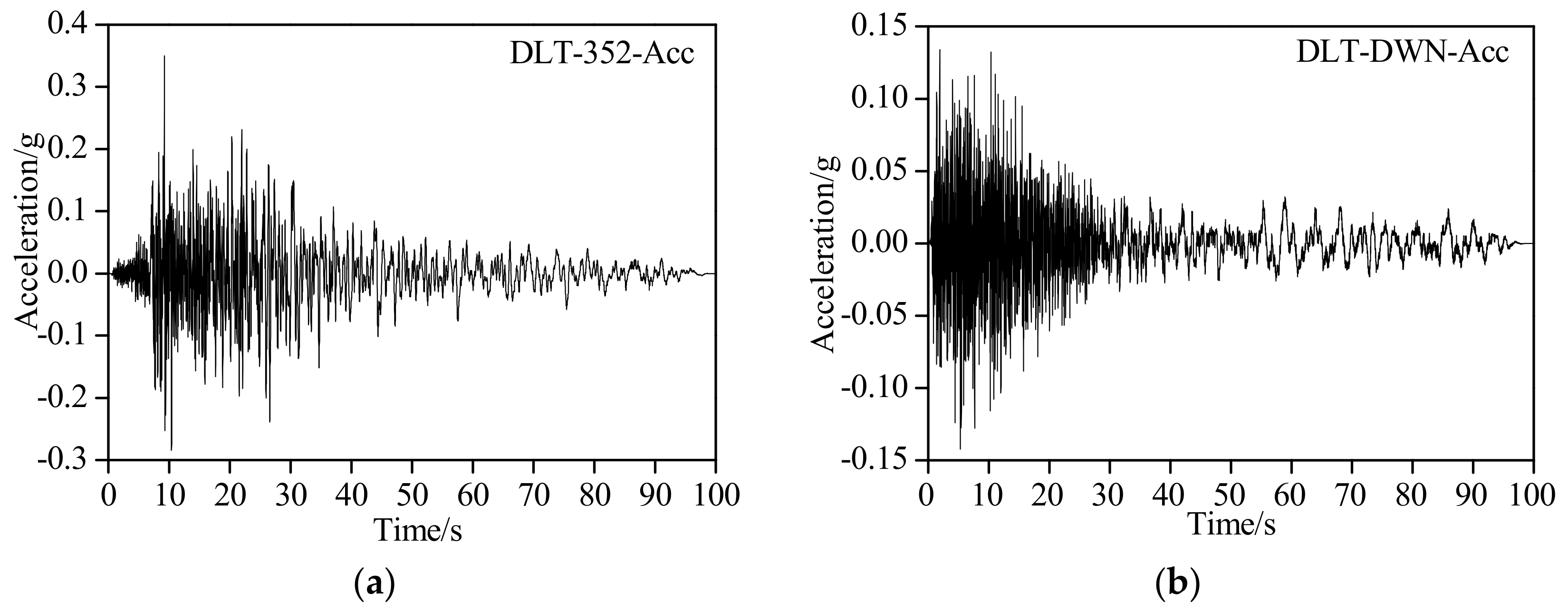
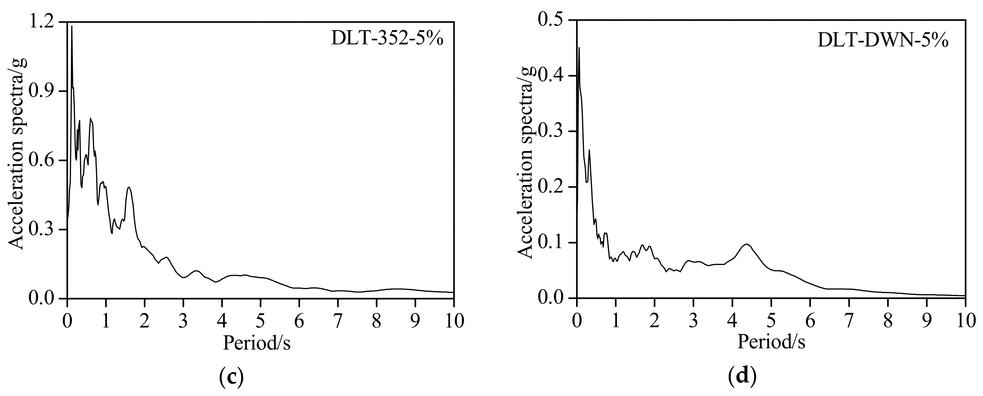
| F6 | DLT | DLT-352 | 0.350 | 1.3(Ux) | 8008 | |
| DLT-DWN | 0.142 | 0.5(Uz) | 7592 |
Publisher’s Note: MDPI stays neutral with regard to jurisdictional claims in published maps and institutional affiliations. |
© 2021 by the authors. Licensee MDPI, Basel, Switzerland. This article is an open access article distributed under the terms and conditions of the Creative Commons Attribution (CC BY) license (https://creativecommons.org/licenses/by/4.0/).
Share and Cite
Lin, Z.; Zhang, C.; Dong, J.; Ou, J.; Yu, L. Dynamic Response Analysis of a Multiple Square Loops-String Dome under Seismic Excitation. Symmetry 2021, 13, 2062. https://doi.org/10.3390/sym13112062
Lin Z, Zhang C, Dong J, Ou J, Yu L. Dynamic Response Analysis of a Multiple Square Loops-String Dome under Seismic Excitation. Symmetry. 2021; 13(11):2062. https://doi.org/10.3390/sym13112062
Chicago/Turabian StyleLin, Zhenwei, Chao Zhang, Jucan Dong, Jianliang Ou, and Li Yu. 2021. "Dynamic Response Analysis of a Multiple Square Loops-String Dome under Seismic Excitation" Symmetry 13, no. 11: 2062. https://doi.org/10.3390/sym13112062