1. Introduction
With the development of power electronic technology, voltage source converter high voltage direct current (VSC-HVDC) transmission technology plays an increasingly important role in power systems [
1,
2]. The application of a modular multilevel converter (MMC) greatly improves the voltage level and transmission capacity of the DC grid [
3]. The MMC-HVDC transmission technology can support the passive system, which is widely applied for the islanded renewable power generation integration systems [
4,
5]. When islanded renewable energy generation power is directly sent out through MMC-HVDC, MMC needs to adopt a constant voltage and frequency (VF) control method to provide grid connection voltage for islanded renewable power generation integration system. However, MMC cannot control the power flowing into the converter station with the VF control mode, which will cause DC overvoltage or bridge arm overcurrent in the case of monopolar converter block, and then cause interlocking failure [
6,
7]. Due to the low inertia and weak damping characteristics of the MMC-HVDC system, the development speed of DC overvoltage and bridge arm overcurrent is very fast. The overvoltage and overcurrent characteristics of this process can be analyzed by electromagnetic transient simulation [
8].
The existing control methods of restraining the rising speed of DC overvoltage and bridge arm overcurrent can be divided into two categories. One is to reduce the output power of renewable energy power generation units and the other is to consume unbalanced power through energy dissipation resistors. The output power of renewable power generation units can be reduced by the frequency rise method or voltage drop method. The frequency raising method is to raise the frequency of islanded system after the failure, and part of the energy store as kinetic energy in the islanded renewable power system [
9]. However, the frequency adjustable range is limited because of the slow frequency detection speed. Therefore, it is difficult to realize the quick adjustment of large-scale renewable energy generation power. In addition, raising frequency will increase the mechanical stress of wind power generation units and affect the operation of wind turbines [
10,
11]. The voltage drop method is to reduce the output AC side voltage of the sending terminal MMC after the failure. Once the renewable energy generation power units detect the low voltage, they will enter the low voltage ride through the process and reduce the output power to solve the problem of DC side power imbalance [
12,
13]. However, at the moment of voltage reduction, the renewable energy generation power unit will produce a large inrush current. The inrush current flows into the sending terminal converter station, which may damage the bridge arm devices. In addition, the sharp fluctuation of the AC grid voltage may cause the crowbar protection action on the rotor side of the doubly-fed asynchronous motor, and also leads to the potential abnormal mechanical stress [
14]. The method of adopting an energy dissipation device is to install an energy dissipation resistor on the AC side or DC side of MMC. To realize the rapid input of energy dissipation device after unbalanced fault, it is necessary to use power electronic devices to start and cut off the energy dissipation device. This method can consume unbalanced power quickly [
15,
16,
17], which is more reliable than other methods, so it is widely used in practical projects. However, this method needs to install a large number of energy dissipation devices, which is difficult to meet the economic requirements of the project [
18]. Moreover, the switching strategy of energy dissipation devices is complex, which is not conducive to the stable operation of the system [
19]. In conclusion, the above methods cannot solve the overvoltage and overcurrent problems of the MMC-based DC power grid perfectly.
A power system can be regarded as a comprehensive and symmetrical power supply and consumption system, facing many unprecedented threats and challenges from urgent low-carbon demand, uncertain renewable energy integration, serious natural disasters, rising energy costs, and so on. In particular, with the popularity of converters and distributed energy, the asymmetry of the distribution network is exacerbated. In order to realize a safe power supply and solve the problem of asymmetry the multi-point embedded topology is proposed, and the reserved margin of the single-point embedded topology and the multi-point embedded topology is compared. Aiming at the problem that the common control methods cannot control the power and voltage at the same time, which leads to the uncontrollable input power of the converter station at the sending terminal, a control strategy based on multi-point embedded topology is proposed. The droop link is introduced into the control strategy to solve the problem of insufficient control dimension. The PSCAD simulation shows that the proposed control strategy can effectively transfer surplus power and avoid serious overvoltage and overcurrent caused by converter block.
2. Analysis of VF Control Characteristics
The double closed-loop control of the converter is used in engineering, as shown in
Figure 1.
uw and
iw are the voltage and current of renewable power generation system parallel nodes.
umc and u
ms are MMC output voltage and point of common coupling (PCC) voltage, respectively.
Req and
Leq are the equivalent resistance and reactance between the converter station and PCC point, respectively. The subscripts “d” and “q” respectively represent the d-axis and q-axis components in the dq rotation coordinate system, and the superscripts “*” represent the reference value.
The renewable energy generation system presents the current source characteristics, and the
isd and
isq in
Figure 1 are determined by the external circuit. Under the VF control mode, the reference setting value of the outer loop voltage is constant, i.e.,
u*sd = 1,
u*sq = 0. When the current flowing into the converter station changes, MMC adjusts the output voltage
umc to ensure that the PCC point voltage is constant. In the VF control mode, the reference current of the inner loop current control can track the actual current. MMC presents the voltage source characteristics. Therefore, the PCC point voltage remains constant under different input current levels, so the current (power) flowing into the converter station is uncontrollable. Once the converter station at the receiving terminal fails, it will lead to the problem of DC overvoltage in the DC power grid. If one pole of the sending terminal converter station in the symmetrical bipolar structure blocks, it will lead to the overcurrent problem of the bridge arm.
In Equation (1), ΔP is the unbalanced power, Ud0 is the initial value of DC voltage, Ud is DC voltage after fault, Ceq is the equivalent capacitance of DC system, equals 6 C0/N, C0 is the sub-module capacitance, and N is the number of the sub-module capacitance of a single-phase bridge arm of MMC.
In the existing project, the equivalent capacitance parameter is millifarad, the surplus power is thousands of megawatts, and the rated voltage of the DC grid is hundreds of kilovolts level [
20,
21]. When the DC voltage rises to the limit value of protection action, the rise time of DC voltage is tens of milliseconds according to Equation (1). However, due to the mechanical inertia, the response time of the renewable energy generator is hundreds of milliseconds. Therefore, there is a mismatch between the power control response time and the DC voltage rise time. It will damage the converter stations and cause serious consequences [
22].
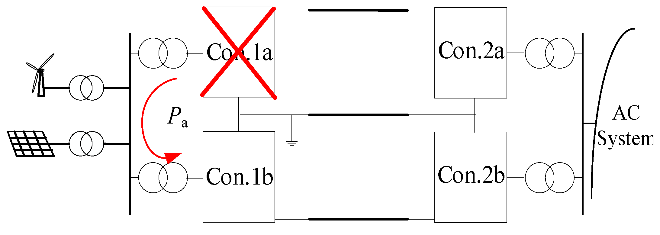
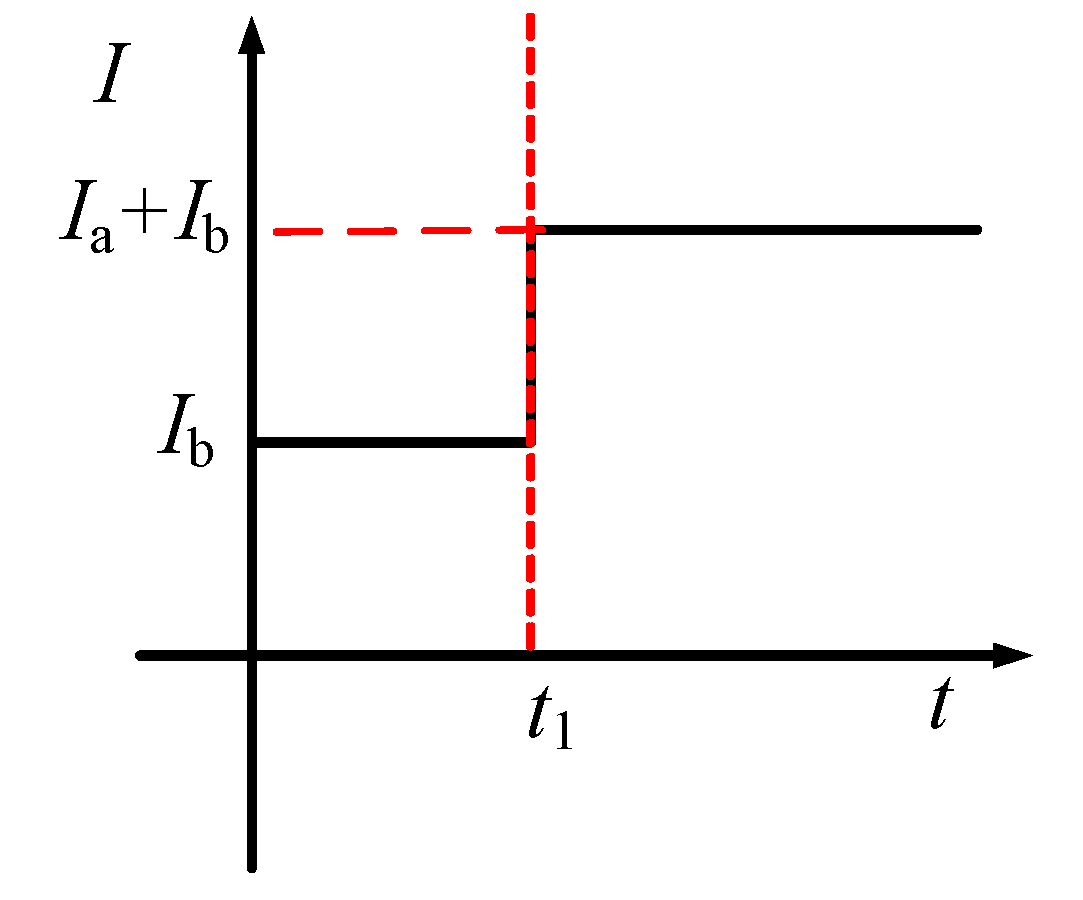
According to the above analysis, the sending terminal converter station shows voltage source characteristics, and the renewable energy power plant shows current source characteristics. Consequently, when the single-pole sending terminal converter station blocks, all the input power of the fault pole converter will be transferred to the non-fault pole converter rapidly, which will cause the bridge arm current to rise over the threshold. As shown in
Figure 2, the power of a-pole will be transferred to a b-pole after a fault. When the a-pole sending terminal converter block, the AC side current
Ib of the b-pole sending terminal converter steps to
Ia +
Ib due to the constant voltage control of the sending terminal converters, as shown in
Figure 3.
3. New Coordinated Control Strategy Multiple MMC Converter Stations Connected Islanded Renewable Power System
Since each pole of the converters can be controlled independently, in order to ensure the safe operation of the system and improve the stability of AC voltage control and surplus power consumption-ability of MMC-based DC power grid connected to an islanded renewable power generation integration system. This section proposes a new sending terminal topology called multi-point embedded topology, which can solve the problem of insufficient control dimension of conventional single-point embedded topology. The new topology is shown in
Figure 4b, in which the renewable energy generation plants connect to the same AC bus. The control strategy of the new topology is analyzed to achieve converter block fault ride through.
The operation power of the receiving terminal depends on the generation power of the renewable energy generation integration system, so the margin design of the converter station at the sending terminal is considered first.
3.1. Comparison of Two Topology Margins
According to the different connection forms of renewable power generation integration system, the connection forms of sending terminal are divided into “single-point embedded topology” and “multi-point embedded topology” as shown in
Figure 2 and
Figure 3, respectively. The single-point embedded topology means that each renewable power generation plant connects one converter station directly. There is no connection between different renewable energy systems. Multi-point embedded topology means that there has an electrical connection between different renewable energy systems, forming a large-scale equivalent renewable power generation plant to send out through the sending terminal of the DC grid. It is worth noting that the DC side structure of the two topologies is the same.
According to the analysis in
Section 2, for the single-point embedded topology, in order to avoid the damage of the device caused by the single-pole converter block fault at sending terminal, the minimum margin of each sending terminal converter is
where
PSMn is the margin of the
nth converter and
PSn is the rated capacity of the
nth converter.
Therefore, the overall margin is half of the total rated capacity of all converters at the sending terminal.
With the single-point embedded topology, each converter cannot be used as a standby for each other to avoid the damage of the device caused by the single-pole converter block fault at sending terminal, which will cause a large waste of converter station capacity. For the multi-point embedded topology, there has an electrical connection between the sending terminal converters, which are spare for each other. Therefore, the multi-point embedded topology can improve the reliability on the premise of reducing the reserved margin of the converter station. In this scenario, the reserved margin design principle is when the largest single-pole converter fails, its power can be transmitted to other converters and will not exceed their rated power. According to this principle, the system reserved margin is
where
PSMΣ is the reserved operation margin of the sending terminal converter.
PSΣ is the total rated capacity of the sending terminal converters.
PREN is the rated power of a renewable energy generation system.
PSmax is the rated power of the maximum converter. It can be seen that the reserved margin of the multi-point embedded topology is significantly smaller than that of the single-point embedded topology. Therefore, with the same total rated capacity of the converters, more renewable energy generation power can be transmitted on the condition of the multi-point embedded topology.
The response time scale of the existing security control device is more than 100 ms [
8], which means it is not possible to cut off the surplus transmission power before the fault develops to the protection action limit value. Therefore, the coordination control strategy of the MMC-based DC power grid is considered to solve the problem of overvoltage and overcurrent caused by converter block fault.
3.2. Coordinated Control Strategy of the Multi-Point Embedded Topology
If the conventional control strategy is adopted in the multi-point embedded topology, when the block fault occurs in the sending terminal converter station with constant VF control, the upper control command of the converter station needs to be changed to make the constant PQ station switch to constant VF control. The switching process is complex and the system easily loses stability in the switching process.
Therefore, combined with the system reserved operation margin, a control strategy based on droop control is proposed. All the receiving terminal converter stations are connected to the AC power grid. This paper mainly studies the coordinated control strategy for sending terminal converters. In view of the overcurrent and overvoltage characteristics caused by the block fault of the sending terminal single-pole converter, the control objectives of the coordinated control strategy are as follows:
The unbalanced power after fault can be quickly transmitted to the non-fault converter.
The transmission power of any converter shall not exceed its rated power.
Ensure the stability of AC side voltage.
Combined with the advantages of constant PQ control and VF control, this paper proposes a control method suitable for the sending terminal converters of MMC-based DC power grid connected to an islanded renewable power generation integration system.
The probability of two V/F controlling converter stations occur fault at the same time can be ignored. Therefore, it is proposed to select two converters to adopt V/F voltage control, which can ensure the voltage support of the sending terminal. Meanwhile, in order to make the change of active power reflected in the frequency, the real-time active power is introduced into the frequency given link, which is named the P-F link. The new control method is named P-F/V control. The control diagram is shown in the red outline of
Figure 5.
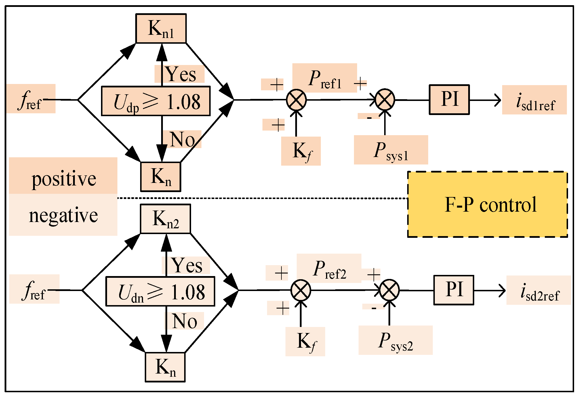
With the introduction of frequency tracking results, the change of frequency caused by fault can change the active transmission power of the P/Q controlling converter, which is named as F-P link. When the system frequency rises, the active transmission power will increase. On the contrary, the active transmission power will decrease when the frequency falls. The above new control method is a typical droop control, which is named F-P/Q control. The control diagram is shown in the black outline of
Figure 5.
Based on the above control strategy, the voltage support for islanded renewable power generation integration system can be guaranteed firstly. Secondly, each converter station can independently control the power flowing into the converter station, thus the communication problem between the converter stations can be solved. According to the power system operation guidelines, the normal operating frequency range of the AC side is 48–50.2 HZ [
23]. Connected with islanded renewable power generation integration system, the sending terminal converter station operates in the rectifying state. Combining the above characteristics, the coefficient of droop control can be obtained according to the slope of the curves shown in
Figure 6.
3.3. Effectiveness of the Coordinated Control Strategy
Supposing that there are
poles in the sending terminal, 1-pole converter and 2-pole converter adopt F-P/Q control and the remaining
−2 poles adopt P-F/V control. The unknown quantity in the system is
x = [
usd,
usq,
usd1,
usq1,
usd2,
usq2, …,
usdn,
usqn,
iLd,
iLq,
isd1,
isq1,
isd2,
isq2, …,
isdn,
isqn,
f1,
f2,
pL,
p1,
p2, …,
pn,
qL,
q1,
q2, …,
qn]. There are 6
n + 6 unknown quantities in total.
usd and
usq are the d-axis and q-axis voltage of AC bus voltage, respectively.
usdi and
usqi are the d-axis and q-axis AC side voltage of the
i-pole converter, respectively.
isdi and
isqi are the d-axis and q-axis AC side current of the
i-pole converter, respectively.
f1 and
f2 are the AC-side system frequency of 1-pole and 2-pole converter, respectively.
pi and
qi are the active power and reactive power of the
i-pole converter respectively. In order to keep the AC side frequency stable, the P-F/V control must be adopted for the converters which have the same capacity.
The Li is the line inductance between the renewable power system and the i-pole converter. There are 2n + 2 equations in Equation (5).
The transmission active power and reactive power of renewable power systems are
pL and
qL, it can be seen as known quantities.
For two poles with P-F/V control, the control equations are shown as Equation (7).
For
n−2 poles with F-P/Q control, the control equations are shown as Equation (8). There are 10 equations in Equation (7).
The f is the tracking result of PLL and can be considered as a known quantity. Equation (8) has 4(n − 2) equations.
According to Equations (5)–(8), the total number of equations is 6n + 6. Since the number of unknown quantities is equal to the number of equations, the system of equations has a unique solution, so the proposed control method can be stable.
3.4. The Post-Fault Characteristic Analysis of the Coordinated Control Strategy
The single-pole block fault at the sending terminal can be divided into two types: P-F/V controlling converter block and F-P/Q controlling converter block. On the premise of a reasonable reserved margin of converters, if one of the P-F/V controlling converters blocks, the remaining converters can realize the stable control of PCC voltage. Additionally, the fault will change the frequency of the P-F/V controlling converter, and then increase the reference active power of F-P/Q controlling converters to transfer the surplus power at the sending terminal. If the F-P/Q controlling converter block, the frequency change caused by the fault will lead to the change of power, which will lead to a fault and will cause the frequency change of the P-F/V controlling converter. It can ensure that the power of the P-F/V controlling converter adapts to the frequency change.
In addition, when a single-pole converter block fault occurs in the receiving terminal, the surplus power of the fault pole can be transferred into the non-fault pole by switching the droop coefficient of the F-P link to slow down the rising speed of DC voltage, as shown in
Figure 7.
When the DC voltage exceeds the threshold value after block fault occurs at the receiving terminal, the reference active power value of the sending terminal converter is changed by changing the F-P droop control coefficient of the fault pole and the non-fault pole. Therefore, the non-fault pole layer can accept more active power to reduce the surplus power of the fault pole layer.
4. Simulation Analysis
In order to verify the effectiveness of the proposed coordinated control strategy when the single-pole converter occurs block fault. A 4-terminal MMC-HVDC grid model is established as shown in
Figure 8. S1 and S4 are sending terminal converter stations. S2 and S3 are receiving terminal converter stations. The rated parameters of the system are shown in
Table 1,
Ps is single-pole converter rated power,
C0 is the capacitance of the sub-module,
Larm is the bridge arm inductance,
Us is the rated voltage of AC bus and the number of sub-modules is 100. S1 and S4 both adopt constant VF control. S2 adopts constant DC voltage control and S3 adopts constant active power control.
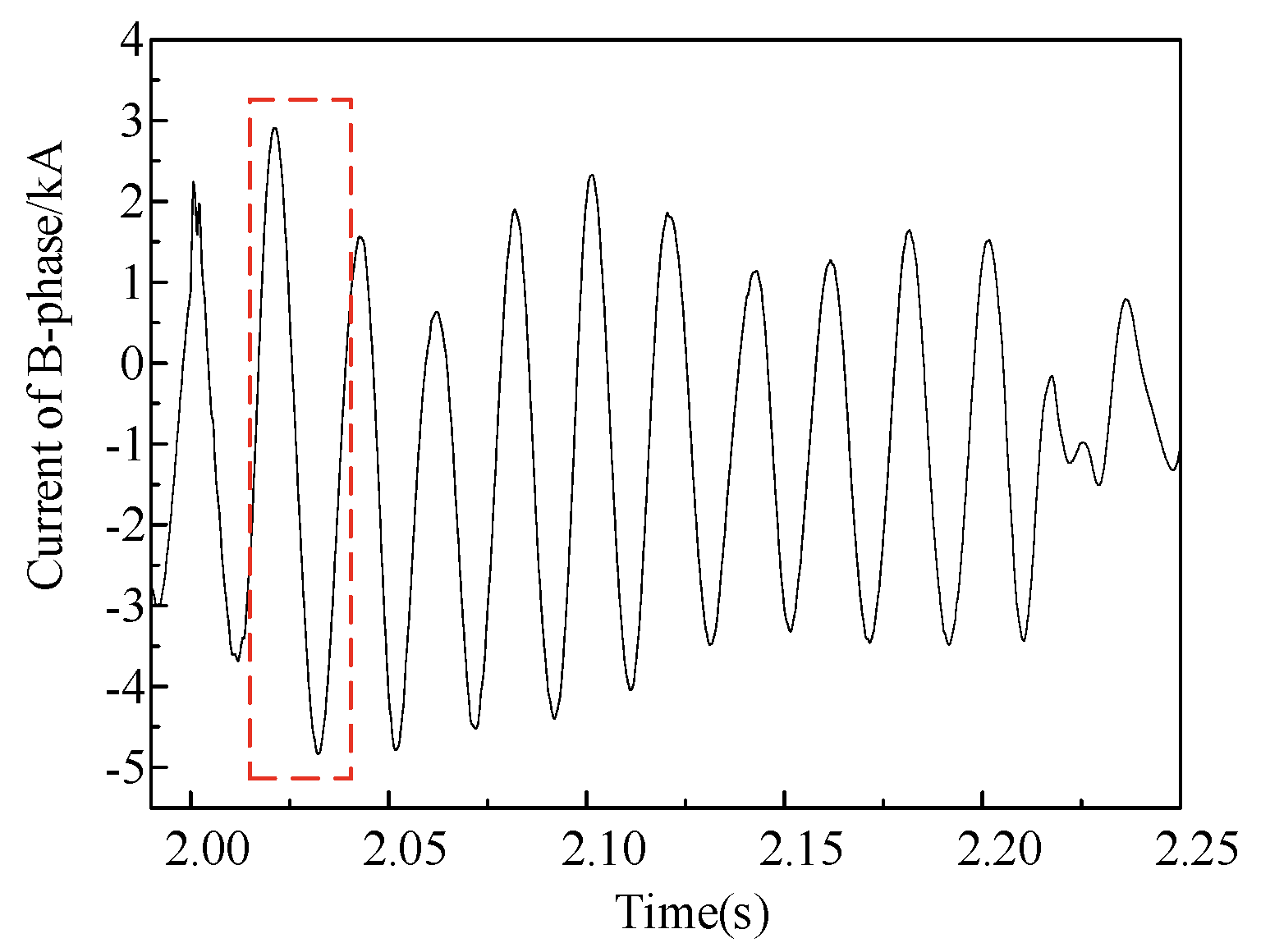
Figure 9 is the overvoltage waveform caused by single-pole receiving terminal converter block fault when conventional control strategy is adopted.
Figure 10 is the overcurrent waveform. It can be seen that the overvoltage and overcurrent are serious in case of fault when the conventional control strategy is adopted.
The AC side of S4 and S1 is connected to the same AC bus. P-F/V frequency droop control is adopted for the positive and negative pole of station S4, and F-P/Q droop power control is adopted for S1. According to the rated capacity of S4 and S1 stations, the operation margin should be 1500 MW, and the generation power of renewable energy power system is 3000 MW.
Three simulation examples are set up to verify the effectiveness of the proposed strategy.
- Case1:
Renewable energy generation power fluctuation.
Case1 is set up to verify the control performance of the proposed coordinated strategy when the renewable energy generation power fluctuates in normal operation.
The initial power of sending terminal is 3000 MW, and the transmission power of the S1 converter station is 1000 MW, and that of S4 is 2000 MW. When
t = 2 s, the generation power rises from 3000 MW to 3400 MW in 0.5 s. The electrical quantity changing process of converter stations is shown in
Figure 11.
As shown in
Figure 11a,c, the fluctuation power flows into S4, resulting in the increase in frequency with the P-F control. It leads to an increase in the active power of the S1 converter station under the F-P control. As the constant reactive power control is adopted in the S1, reactive power does not change in the whole process shown in
Figure 11b. In order to maintain the stability of AC voltage, S4 absorbs part of reactive power from the renewable power generators shown in
Figure 11a. As shown in
Figure 11d, the AC voltage remains constant throughout the process.
- Case2:
Single pole converter block at the sending terminal.
(1) Voltage controlling converter block fault.
At 0.3 s, the system loses a voltage controlling pole converter because of the positive pole converter of the S4 block due to the fault. The simulation curve is shown in
Figure 12. It can be seen from
Figure 12a that after the positive pole of the S4 block, the power is rapidly transferred to the negative pole of S4. Because of the P-F control logic, the increase in incoming power of the converter station increases system frequency, as shown in
Figure 12b. Due to the influence of F-P droop control, the transmission power of S1 increases, to ensure that the negative pole converter of S4 will not overload. In
Figure 12c, the system voltage can keep stable because the VF control system of S4 works. In
Figure 12d, the degree of overcurrent is far less than that of a conventional control strategy.
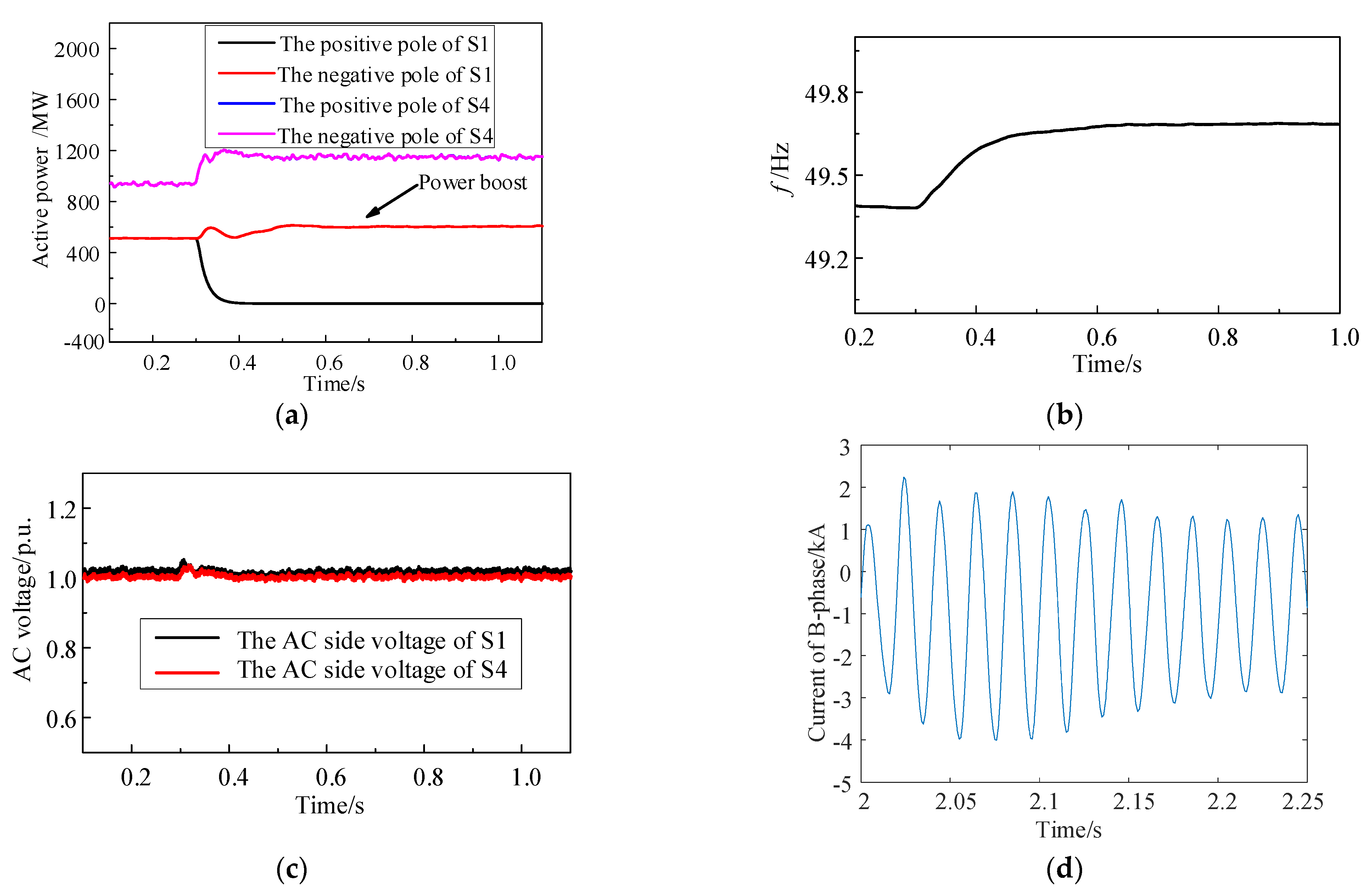
(2) PQ controlling converter block fault.
At 0.3 s, the positive pole of S1 occurs block fault. The active power curves of S4 and S1 are shown in
Figure 13a. It can be seen that the active power of the S1 negative pole is rapidly transferred to S4 and evenly distributed by the positive and negative poles, which causes the system frequency to increase. The changing process of frequency is shown in
Figure 13b. As the frequency increases, the transmission power of the S1 negative pole increases rapidly to ensure that the S4 transmission power does not overload. The system voltage is stable after block fault, as shown in
Figure 13c. The degree of overcurrent is less than that of conventional control strategy, as shown in
Figure 13d. The effectiveness of the control strategy is verified.
The simulation results show that the proposed coordinated control strategy can keep the AC voltage of the renewable energy side stable. Meanwhile, the transient power that generated by the receiving-end or sending-end fault station, will not lead to the overvoltage of the DC side.
- Case3:
Single-pole converter block at the receiving terminal.
According to the reserved margin design principle of the above analysis, the transmission power of converter stations is shown in
Table 2. It can be seen from the power of S1 and S4, the multi-point embedded topology system can send 750 MW active power more than the single-point embedded topology system with the parameters in
Table 2. The initial power of the single-point and multi-point embedded topology system is shown in
Table 2.
When
t = 2 s, the receiving terminal converter station block. As seen in
Figure 14a–c, the active power of the converter station cannot be controlled with the single-point embedded topology. With the multi-point embedded topology, part of the fault pole power can be transferred to the non-fault pole, ensuring DC voltage will not reach the protection setting value within 160 ms after the fault.


