1. Introduction
Mathematics has been used to solve geometric problems throughout history, something that has proliferated with the possibility of establishing metric (e.g., distances or angles) and geometric (e.g., parallelism or perpendicularity) variables for analysis, or implementing such variables in the development of computer-aided design (CAD) software. Such augmentations have become increasingly powerful, such that neither hand drawing—with either classical instruments or Euclidean tools (compass, set square, and bevel)—nor the need for in-depth knowledge of classical-geometry procedures are essential for designers anymore.
Hence, many design-related institutions have replaced some of their classical-geometry material to ensure that students receive proper training on the use of the CAD tools involved in three-dimensional (3D) geometric modeling processes [
1,
2,
3]. However, classical geometry is often needed for sketching, a complex and broadly applied process in the design field [
4].
The multidisciplinary teams involved in the implementation of the most commonly used CAD software in engineering [
5] collect user feedback to solve the problems they encounter and make improvements to simplify procedures. These improvements are developed from mathematical algorithms [
6], resulting in appropriate graphic representation.
Following the introduction of parametric design, in recent decades, CAD software has progressed towards the integration of computer-aided engineering (CAE) tools. Although traditionally they have been considered separately, the unification of design software with engineering analysis tools such as finite-element analysis (FEA), offers the advantage of reducing time and cost in design, as well as the standardization of formats between providers [
7]. For the same purpose, in recent years, the main CAD systems have made progress in the integration of tools for life cycle analysis (LCA). Certainly, the introduction of LCA concepts at an early stage of design also allows us to accelerate the design of new products and save costs. On the one hand, the connection between the geometry of an object, the selection of the material, and the analysis of the life cycle of the product is logical [
8]. On the other hand, it is especially interesting to use these tools to analyze the environmental footprint of products, energy consumption, and propose solutions based on environmentally friendly materials [
9,
10].
Despite the fact that the functionality of CAD software has not stopped growing in recent years, it seems to have found in computer-aided innovation (CAI) a new field of improvement for its systems and a set of emerging tools useful for designers and engineers [
11,
12,
13]. CAI is important for the product design process [
14,
15,
16], and CAD software apparently increases its users’ creative performances [
17]. The main tool for such innovation is Computer-Aided Sketching (CAS) [
6,
18], which simplifies the human aspect of drawing validation tasks in the engineering context [
19].
Recent scholarly articles have represented the current sketching processes and the importance of research in this field: studies have been carried out from the perspective of product design [
20,
21], taking into account the needs and difficulties expressed by the designers [
22], and from the academic or training point of view [
23]. Studies have also been carried out on the impact of the sketching process on the parameterization of elements [
24] and the 3D sketching process in day-to-day operations and its influence on 3D reconstruction [
25,
26] and previewing [
27]. In this sense, various recent investigations have proposed improvements in the geometric field of CAD programs [
28,
29,
30], making it transparent that there is still an existing gap in improvement in CAD sketching techniques.
Precisely, this article represents a significant contribution through reintroducing concepts that geometry experts had discarded for operational reasons in CAD Software. An example from Euclidean geometry is the problem of Apollonius [
31,
32], where a circumference tangential to three given circles in a plane had to be found. In the 16th century, Adriaan van Roomen solved the problem using intersecting hyperbolas [
33]. However, François Viète improved upon this method by exploiting the assimilation points and lines as extreme cases of circumferences [
34].
The appearance of parametric CAD software was a major milestone for geometry generation based on the modification of parameters associated with geometric conditions affecting one or more entities; similarly, the introduction of other intermediate graphic entities with certain geometric conditions would simplify the development of 3D space. This also applies to two-dimensional (2D) space because most 3D shapes are generated from 2D shapes through operations such as extrusion, revolution, or sweep.
This research demonstrates the substantial improvements possible for 2D- and 3D-design processes through implementing relevant and widely used geometric-place (both plane and spatial) applications in the currently available commercial CAD software. Consequently, the incorporation of geometric places into CAD software could increase technical-design productivity by eliminating some intermediate operations, such as symmetry, and improving the geometry training of less skilled users.
Academically, this implementation––the object of future research and development––could be used for CAD teaching purposes in design-related schools and institutions worldwide.
Background
Although graphic entities meeting certain geometric criteria have previously been suggested by renowned mathematicians and geometers, difficulty obtaining the graphic part has previously complicated their use. In the past, problems were always reduced to the plane, and geometers believed that the use of curves not drawn with a compass was inelegant.
A common consensus regarding the definition of a geometric place or locus describes it as a set of points that satisfies one or more of these properties [
35]: distance, angle, or some other parametric feature. A practical locus problem is found in Aristotle’s Meteorology [
36].
It is common to speak of equidistance in the context of the property of distance, that is, points that are at the same distance. Thus, given a fixed point, a locus can be derived from the points that meet the condition of being at a fixed distance from the given point; this is the circumference. The concept can be expanded further: in three-dimensional space, the third dimension, z, can be used to obtain the expression ; this is the sphere equation, defined by points that are equidistant from a fixed point, which is the center of the sphere.
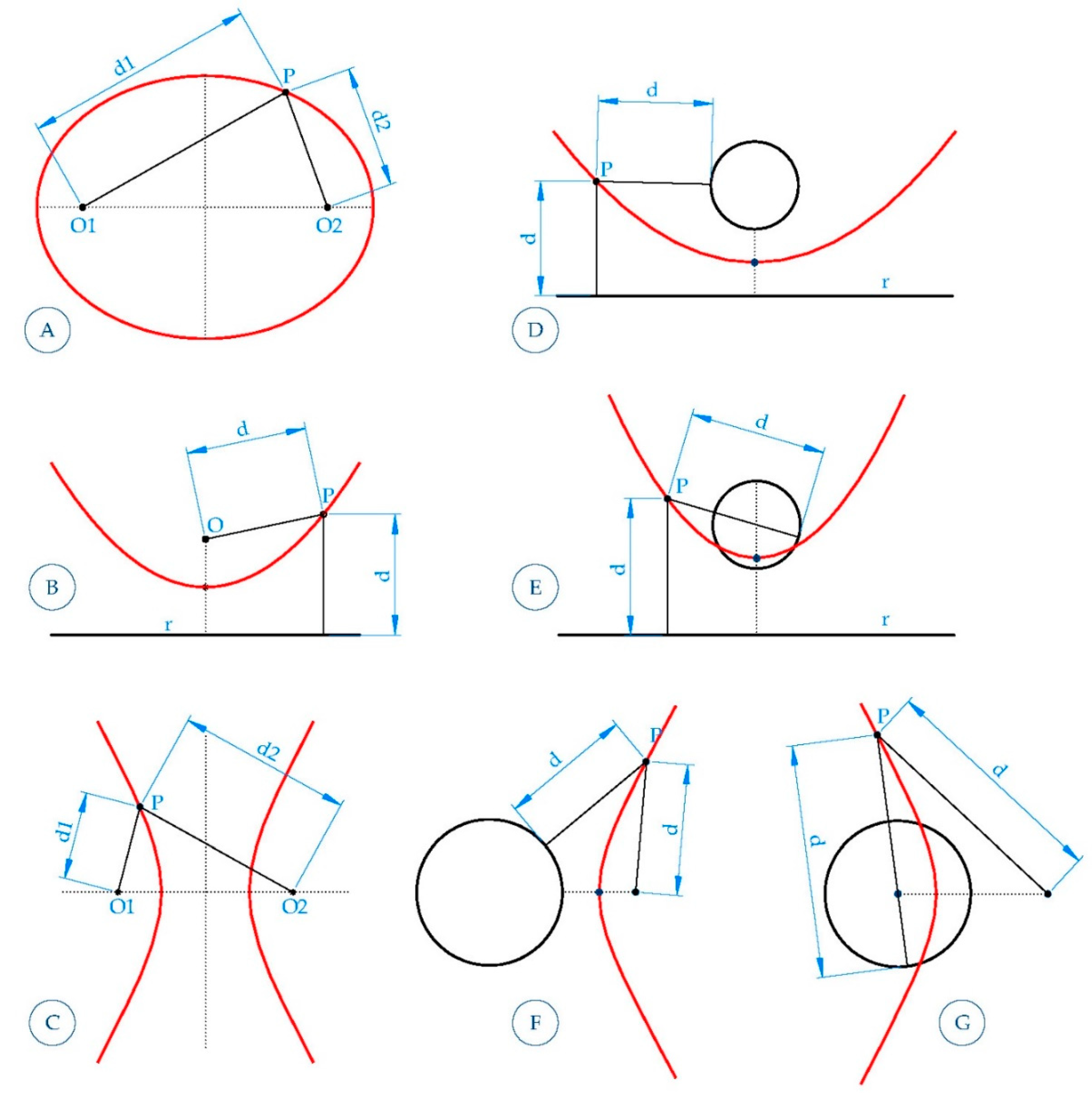
All conical curves can be defined as loci relating two entities, either as points to each other (ellipse as a sum of distances), point and line (parabola), or the difference in distances to two points (hyperbola). Furthermore,
Figure 1 shows that the condition of the point changes according to the circumference.
Equally, as with the extension to the three-dimensional space of the circumference, the sphere was obtained from the ellipse, the ellipsoid of revolution would be obtained from the parabola, the paraboloid of revolution, and from the hyperbola, the hyperboloid of revolution.
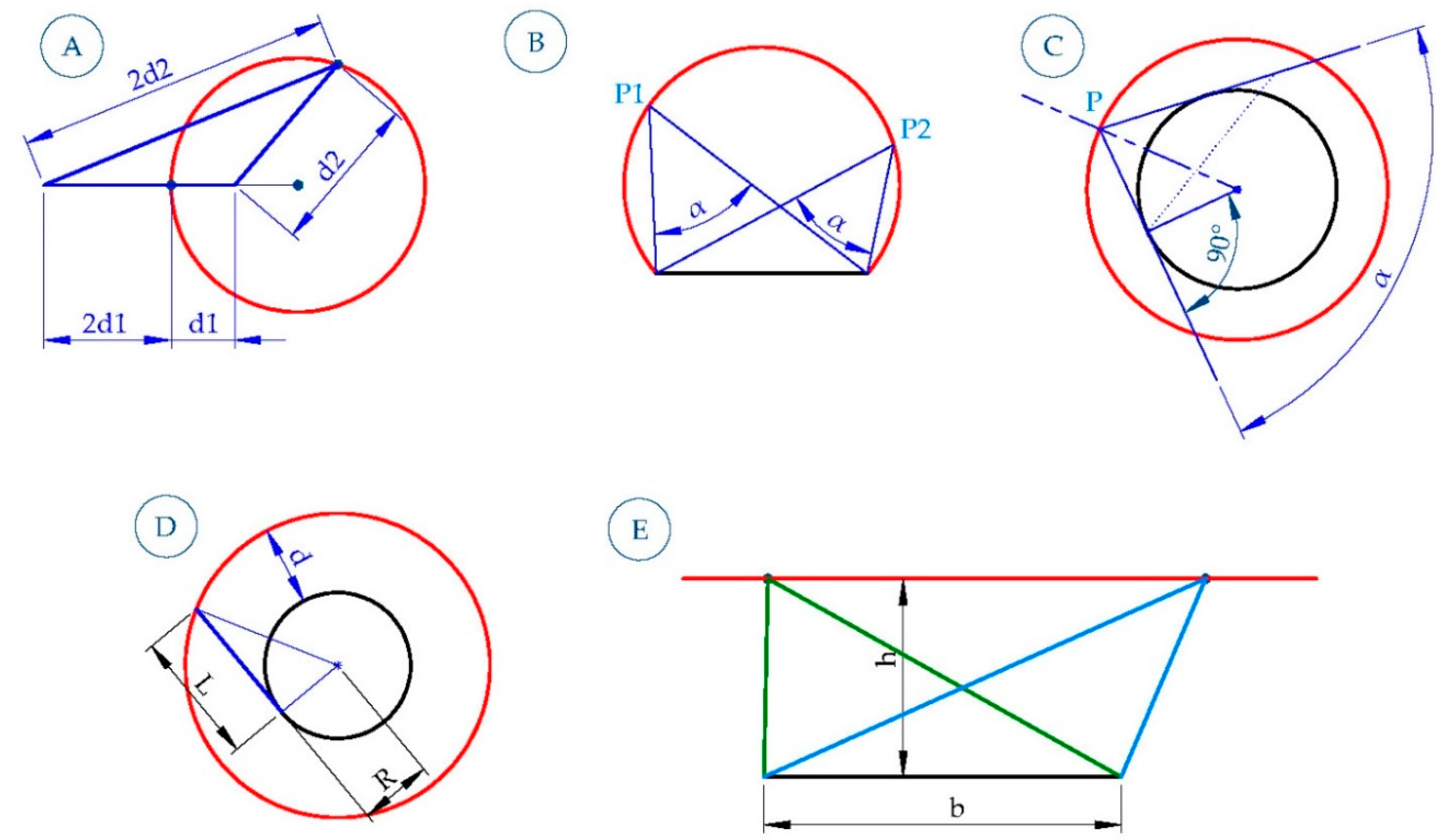
The geometric places described thus far use the property of equidistance. However,
Figure 2 presents some examples of how they may be derived from other distance properties (minimum, maximum, or proportional distance) or angles.
As the geometric places method has become the common ground for solving geometric problems in engineering in the last 30 years, the most powerful software applications have begun to explicitly or implicitly exploit different possibilities of the locus concept, such as in auxiliary tools for 2D design. However, the concept has not been fully developed, leading this article to emphasize its broad possibilities, such that the most useful geometric places for 3D design are visible and implemented in commercial CAD software. The article hypothesizes that implementing a set of functions to illuminate geometric places in commercial CAD software will simplify and facilitate the design process for users. Therefore, the main objective of the paper is to demonstrate the theoretical benefits of implementing loci functions in CAD software.
The remainder of the paper is structured as follows:
Section 2 explains the methods;
Section 3 reflects on the findings;
Section 4 presents the research’s conclusions.
2. Methods: A Novel Focus of Locus
As shown above, the number of possible loci is virtually unlimited. This article intends to develop the theory using some of the most practical geometric places as a model, in order to implement them on 3D design CAD software in the future. Among these are those formed by lines or circumferences. These are well known in classical geometry. However, those presented here are curvilinear. The only requirement is that the CAD software can draw the curves, whether circumferences or another kind of curve.
The theory must be supported with examples—presented from lesser to greater complexity––that allow intuitive understanding of the advantages of implementation and that it includes proposals for accessing the new tools so that they can be integrated as options (e.g., menus or sidebar tools) in the CAD software.
To validate the hypothesis, three examples are presented: one on the plane and two in space. The methodology for solving the examples involved individually considering the different geometric places involved as equations, and then finding the solution for these equations graphically [
36]. The examples were solved graphically using Solidworks 2019 Premium (Dassault Systèmes, Waltham, MA, USA). Editing the images required 3ds Max from Autodesk (San Rafael, CA, USA).
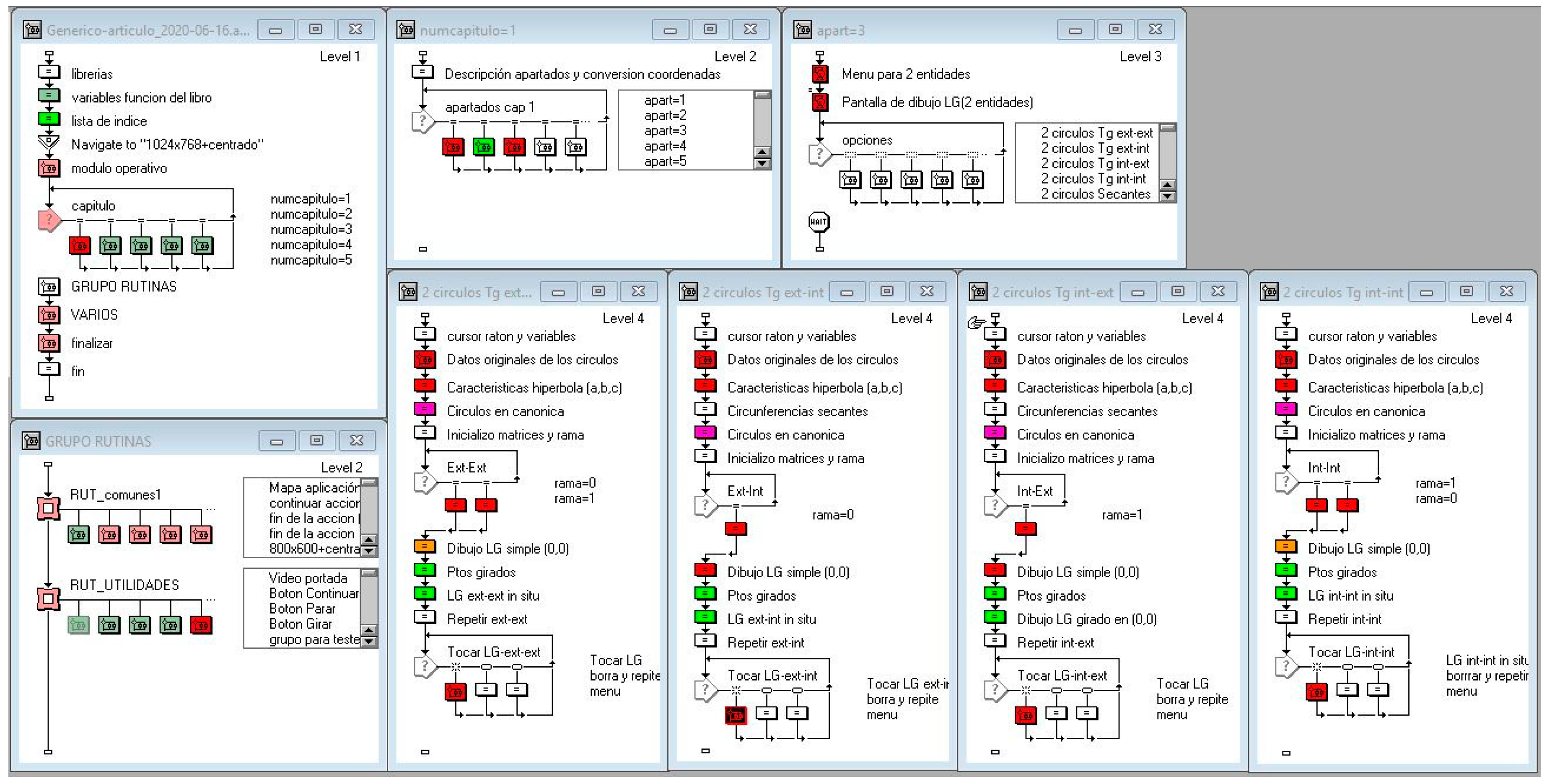
In addition, to facilitate understanding of the scientific proposal and its benefits, an own-software tool developed in Adobe Authorware v7.0.2 (Adobe, San José, CA, USA) is also presented. The tool has not been implemented in any CAD software; its purpose is just academic and demonstrative. Although the software application does not yet have all the geometric places functions implemented, the data structure is shown in
Figure 3. The structure of the computer application is similar to others shown in published data [
37], and it was divided into four levels of functional hierarchy. The first level is the main structure of the program. The second level serves to lead to the proper set of functions according to the number of entities involved. The third level allows the selection of the desired function and the last one, to select the entities and solve the problem. In order to clarify how the developed tool works, an extra locus example is provided and solved.
2.1. Plane Example
The first example is rather elementary: two geometric places incorporating the concept of distance, the perpendicular bisector and the bisector.
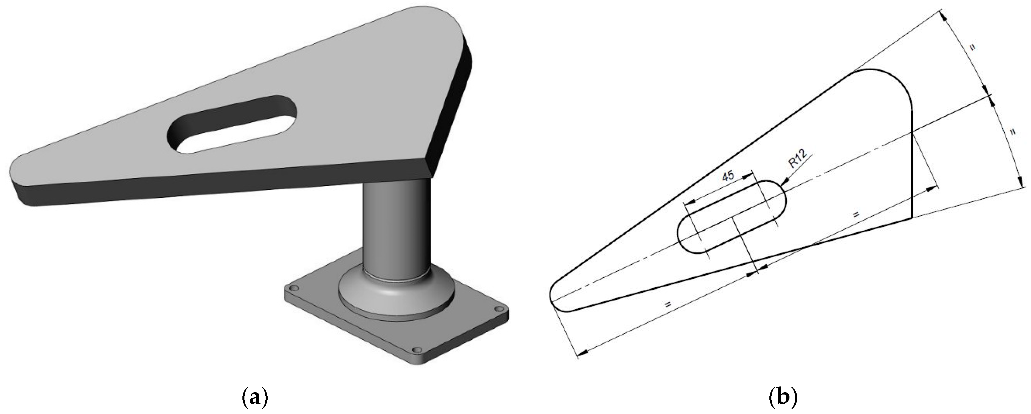
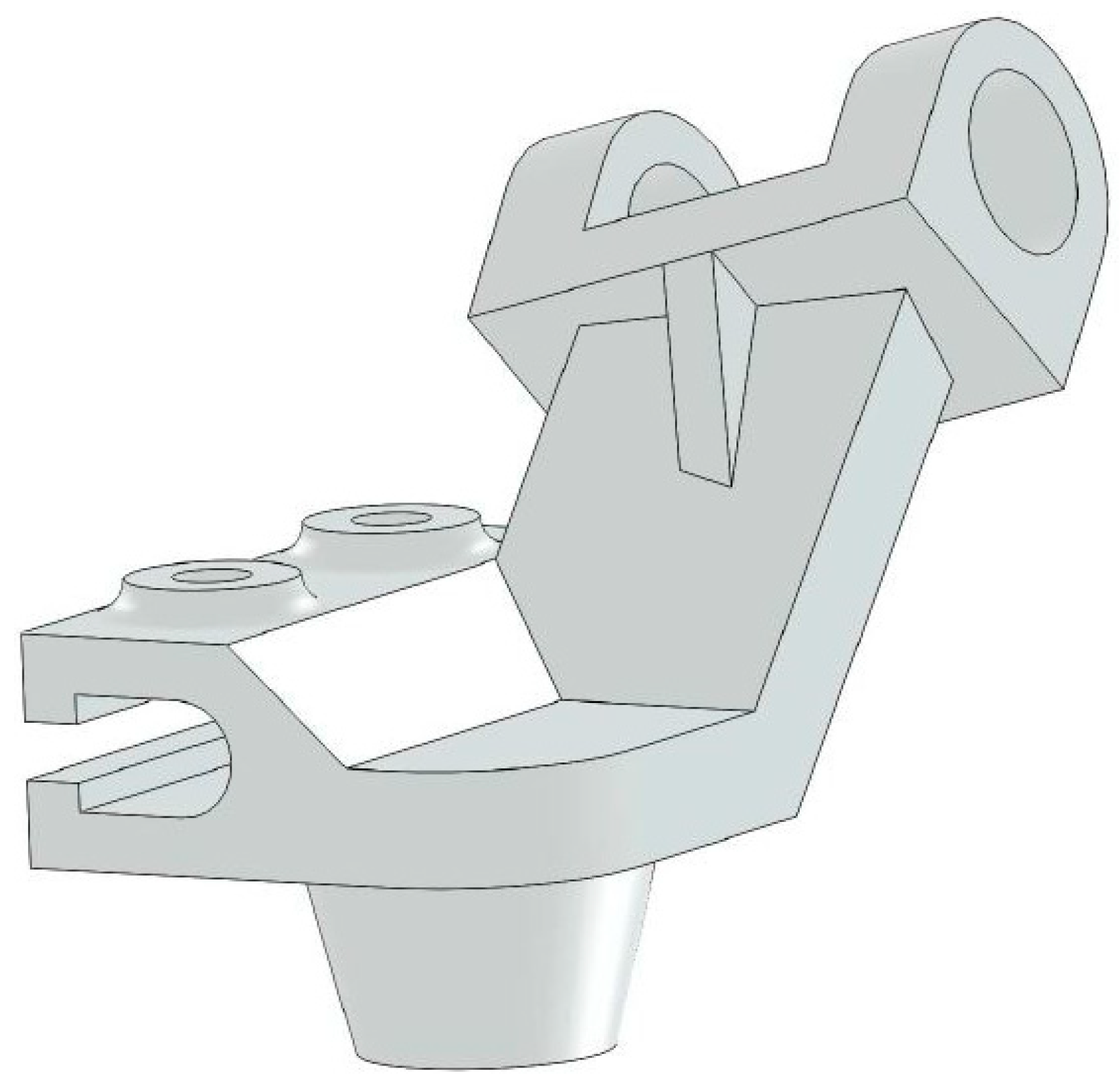
The challenge was, given the outer perimeter of the flat face of an object, which was formed by three straight edges and two arcs of circumference (
Figure 4a), to locate the slot of known dimensions so that its center was on the bisector of the angle formed by the non-perpendicular straight edges and it was at the same distance from the perimeter cut-off points (
Figure 4b).
Using parametric CAD software such as Solidworks, SolidEdge, Autodesk Inventor and Catia, among others, we initially drew a similar shape, and then fit it to the real model by applying dimensional and geometric restrictions. To draw the bisector line, we started from a given point (the center of the left end of the circumference); however, if we needed to find another point, we would, for example, draw another circle tangential to the two lines, and then join the centers of both circles and extend the line to the perimeter. Then, the slot could be drawn and placed at the midpoint of that line.
Using a vector program (e.g., AutoCAD), the bisector could be drawn traditionally or using a tangent circle. Then, we would extend one or both and cut off the bisector to locate the midpoint. To find the centers of the circumferences of radius 12 of the slot, we would have to use another circumference of radius 45/2, draw both circumferences, trace the tangent lines on both sides, and then cut to eliminate the excess lines.
Thus, a possible alternative to the geometric places method is to combine two of the most obvious geometric places: the bisector, being the geometric place defined by the points at the same distance from two lines, and the perpendicular bisector, being the geometric place defined by the points at the same distance from two points. The intersection of these two geometric places determines the center of the slot.
The simplicity of this approach makes it difficult to appreciate the advantages of using these geometric places. However, it can be demonstrated that this approach can be applied to a multitude of cases that previous methods could not so easily solve. Most relevant, however, is that this methodology can be easily applied to three-dimensional space, where it is more complicated to find the correct solution intuitively.
First, it is necessary to demonstrate the usefulness of the concept in three-dimensional space. Two examples are presented. In the first example, curved geometric places are not needed; however, the second example does involve curved surfaces.
2.2. Spatial Example 1
One of the simplest spatial geometric places is the plane bisecting two planes, defined as the plane formed by points that are equidistant from two other planes. When they are parallel, the bisecting plane is also parallel, and very often the nerves—the stiffening elements of a part—are located in the center of said bisector plane. An example of this is shown in
Figure 5. The geometric place would provide the placement of the plane that positions the nerve without having to rely on parallelism or perpendicular restrictions, so that we could generate it even with more than one pair of faces (the outer or the inner planes of the fins). The advantage over other options stands out.
2.3. Spatial Example 2
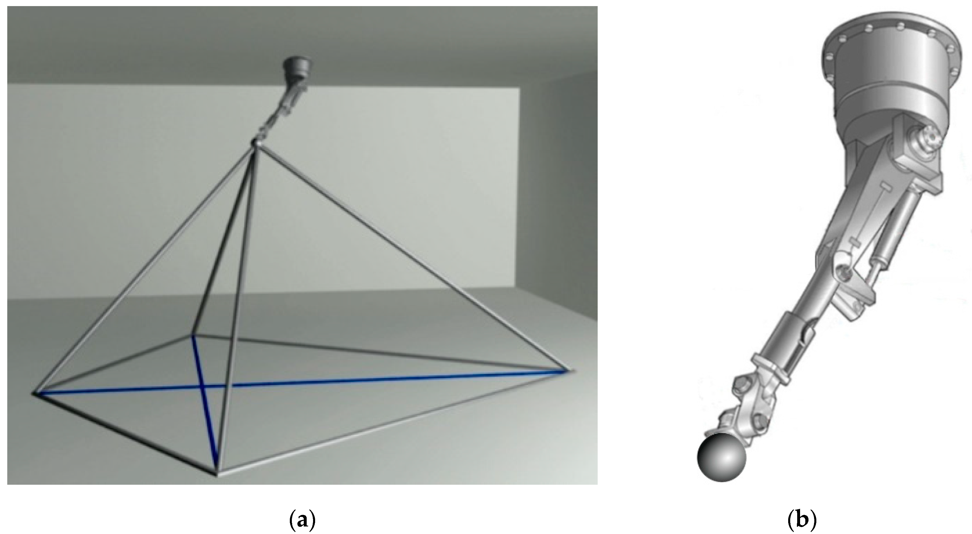
Figure 6 shows that a pyramidal structure with a quadrangular base was modeled to fulfill the following requirements: first, a quadrilateral base defined by two horizontal diagonals perpendicular to each other (
Figure 6a); second, a vertex of the pyramid, where the four lateral edges meet, is located in the center of a spherical ball, held by a mechanical arm attached to the ceiling at a given place (
Figure 6b).
The mechanical arm had to have a fixed length and be able to rotate in any direction (L = the distance from the ball to the rotation center of the arm). Furthermore, the lateral edges had to start from each diagonal, forming a 100° angle at the vertex.
The problem here was positioning the small sphere to meet the conditions described; the lengths of the four lateral bars of the pyramidal structure could be as short as possible.
The following geometric places were involved:
Locus1: The geometric place of the points of the space that observe one of the segments at a 100° angle (spatial “arc capable”; in other words, the surface of revolution generated by a 100° “arc capable” that spans one of the arms of the cross);
Locus2: The geometric place of the points of the space that observe one of the segments at a 100° angle (100° “arc capable” that spans the other arm of the cross);
Locus3: The geometric place of points in space that are at a distance L from the rotation center of the rotating arm (sphere).
After the geometric places that intervene have been determined, all possible solutions can be found. Different approaches are equally valid: solving the intersection between Locus1 and Locus2, and then finding the intersection with the sphere (there would be two solutions on the sphere surface); solving the intersection between Locus1 and Locus3 and then finding the intersection with Locus2; solving the intersection between Locus2 and Locus3 and then finding the intersection with Locus1.
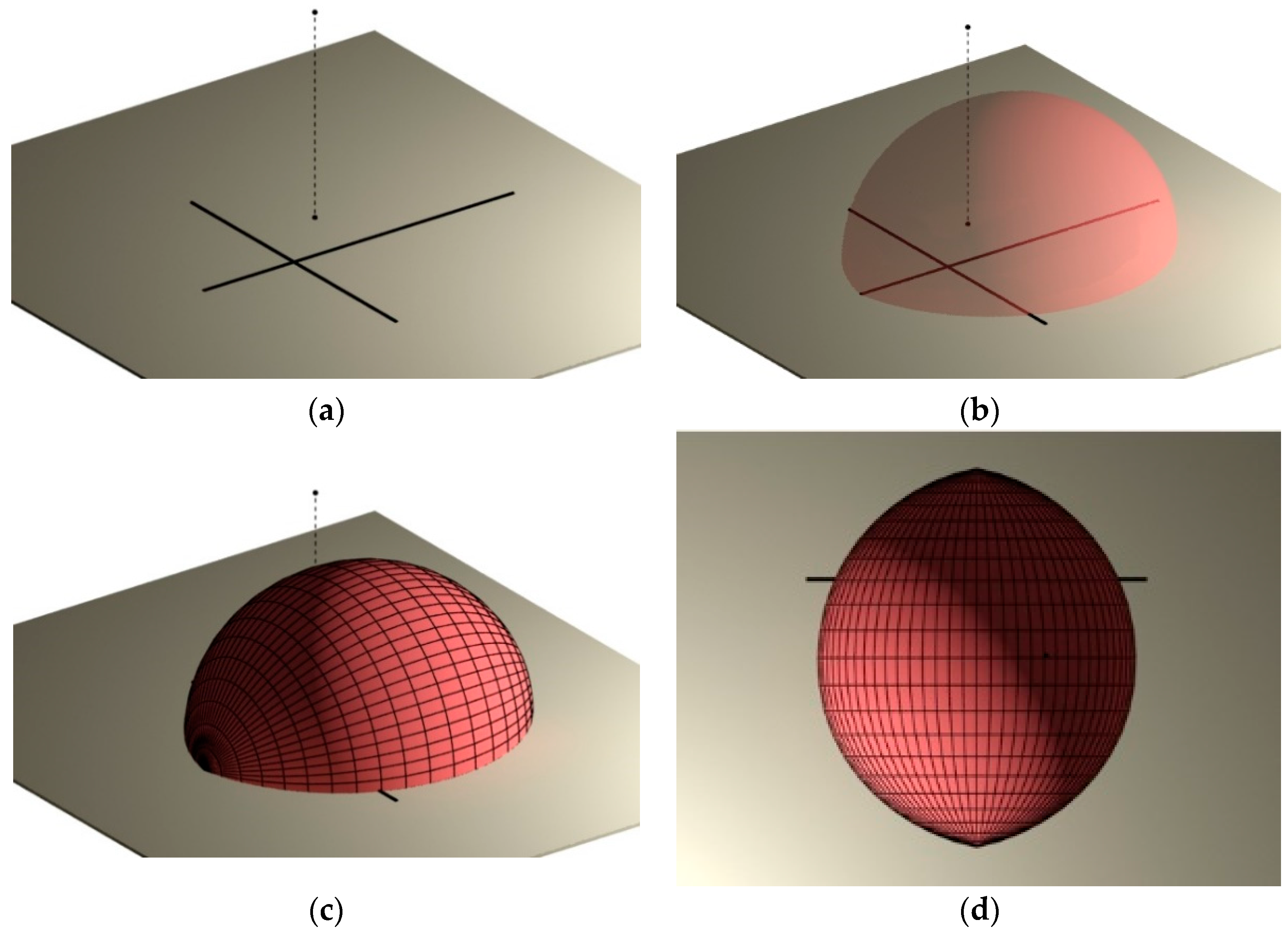
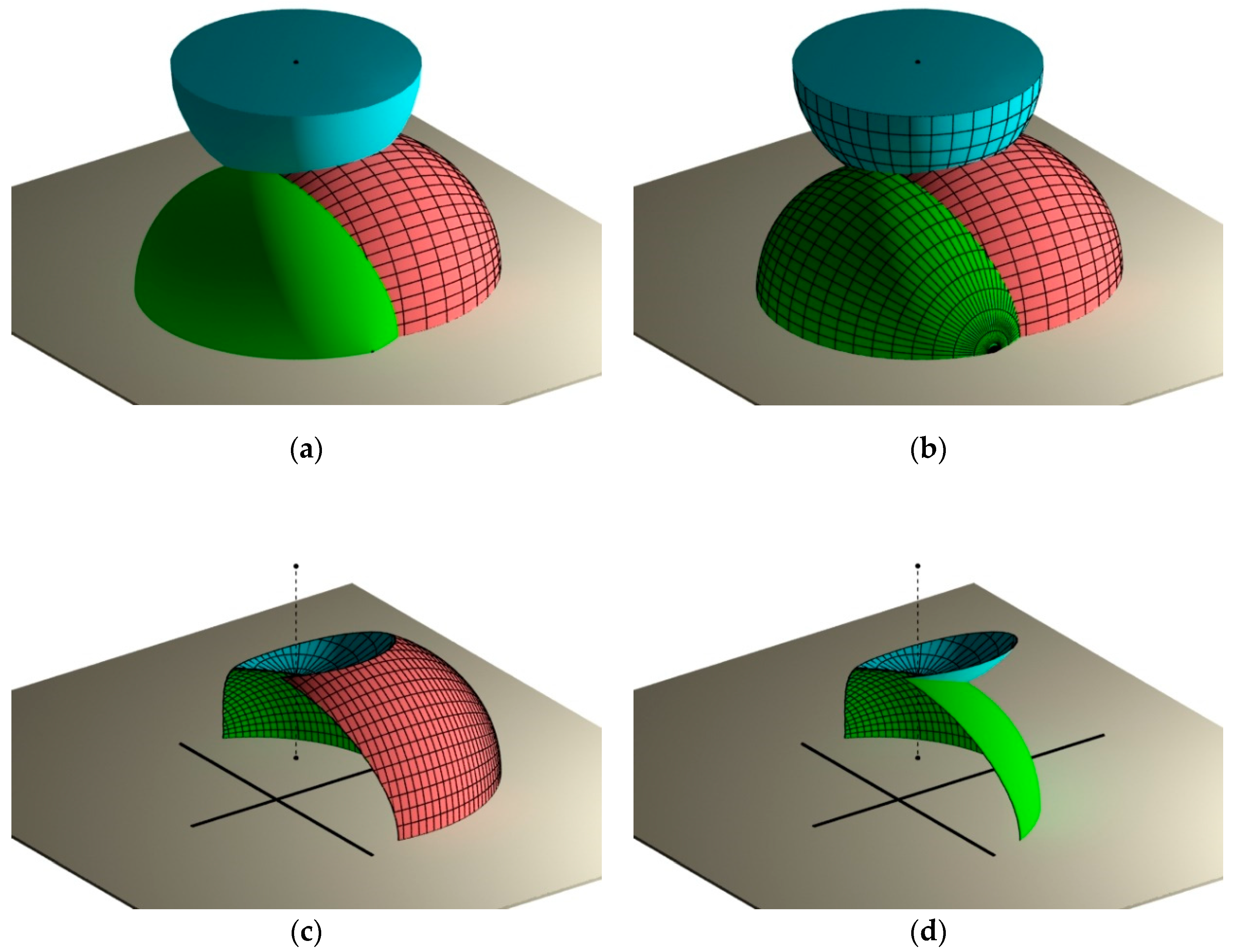
This research uses the last approach as an example, using a series of images (
Figure 7) combining solid and wireframe models and transparencies for a better understanding of the shape and the intersection of the geometric places.
The initial data were the two cross-shaped segments, the point on the ceiling that the arm can rotate on and the length of the arm (
Figure 7a). A perspective view was chosen in order to be more intuitive than dihedral projections.
Figure 7d shows several superior (top view) projections to avoid surfaces generated through the “arc capable” Locus1 and Locus2 being confused with spheres (i.e., because they resemble rugby balls more than spheres).
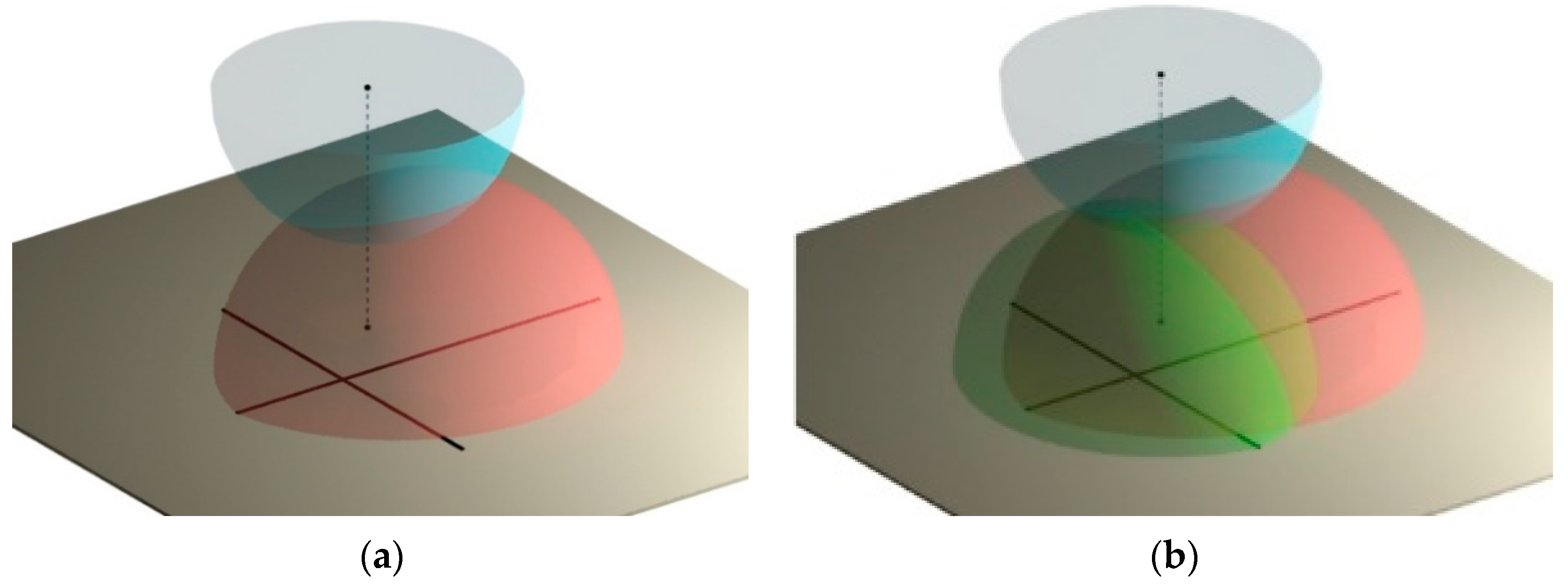
Figure 8a adds a hemisphere as the geometric place where the lower end of the fixed-length arm can move when rotating on its ceiling anchor.
Figure 8b uses transparent solid models to enable a comparison of the three geometric places.
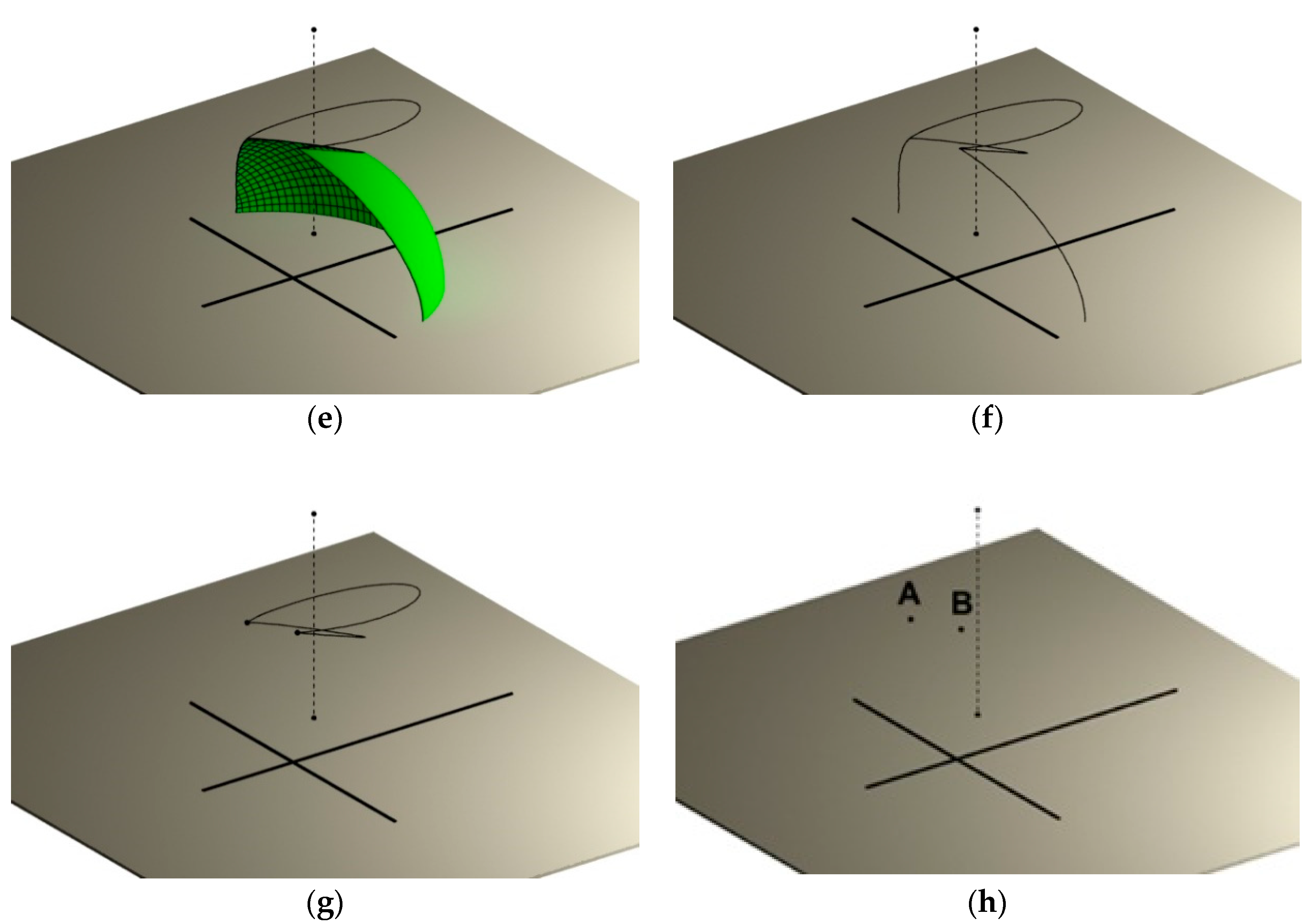
To better illustrate the example,
Figure 9 shows wireframe models of the different geometric places.
Any of the three procedures would lead to an identical solution: the location of the exit points. In this case, the only two possible points are those that appear in
Figure 9h as points A and B; these are the result of finding the intersection of the three geometric places.
Finally, we considered the lengths of the resulting bars. The two solutions meeting the initial requirements were deemed correct.
The procedure’s mathematics would comprise solving the equation system generated by applying the boundary conditions. In other words, the three graphic elements would be taken to an analytical level. However, it has been demonstrated that the images are much more illustrative than the mathematics would be, especially for the geometric places that correspond to a spatial “arc capable”.
2.4. Locus Example Solved with Developed Tool
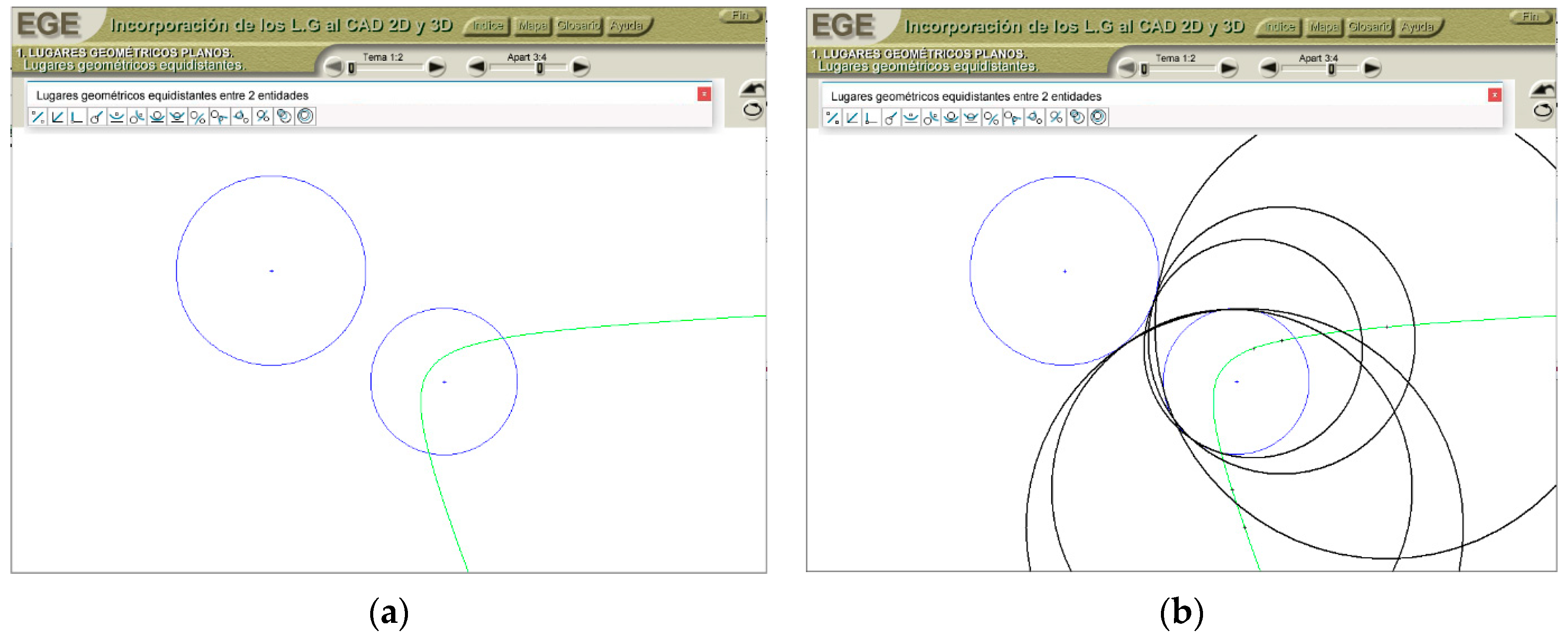
In this sample, a basic case of locus equidistant to two entities is presented. Two circumferences are given (with diameter and center known), and it is requested to find the locus of all the centers of the circumferences that are exterior tangents to the upper circumference and interior tangents to the circumference placed at the bottom. The developed tool provides the solution to this problem by clicking on the proper function icon and, later, clicking on the two entities given in the proper order. Automatically, the tool represents the solution to the problem by generating a construction curve (
Figure 10a, in green), where all the centers of circumference’s tangent to both entities are located in the conditions of the statement (some of them represented in
Figure 10b, in black).
3. Reflections
Before the advent of computers, the geometric places that could be represented using traditional instruments or Euclidean tools (compass, set square, and bevel) were used in the service of drawing designs. The geometric places were based on very simple concepts—such as distance or angle equality—and could be easily drawn with such tools.
Though the first personal computers had little graphical processing power, when graphical processing became more powerful, applications that reproduced human design work were released, albeit with limited scope. Over time, they evolved to take advantage of their increasing capacity for calculus and providing automatic solutions to the problems of classical geometry. Still, the lines or curves those calculations implied were not visible.
More recently, CAD software has been significantly improved through incorporating relative-position relationships between entities; these relationships include parallelism, perpendicularity, concentricity, tangency, or distance equality.
Methodologies changed in recent years, allowing graphic entities to adapt to any given design condition through restrictions or parameters, improving functionality. However, the inability to use equidistant curves complicates choosing the appropriate entities’ positions, so they can be adjusted later to their final state by incorporating said restrictions or parameters. Hence, this research has substantial potential practical applications.
Upon understanding the procedure’s dynamics—especially given the infinite number of geometric places that can be determined—it is convenient to limit the system to illuminating only the most useful geometric places, a feature that 3D design experts would like CAD software to have.
A broader analysis could be done, but only in space, since the plane could be considered as the intersection of the spatial geometric place with the plane. However, given that the planes are more recognizable, they will be considered separately.
Given that this article demonstrates that the incorporation of geometric places into CAD software represents an improvement in 3D CAD design, the main objective of this research is to promote the functionality and competitiveness achieved by taking the system to 3D space. In this context, the first example has enabled the identification of auxiliary operations of classical geometry, including the bisector of an angle formed by two edges and the perpendicular bisector of a segment, which has not yet been implemented in the most commonly used CAD software. The second example identified the intuitive functions of geometric places in space, including the two-sided bisector plane, the equidistant plane at two points, and the paraboloid equidistant from a plane. Currently, obtaining these geometric places through CAD software is not carried out through the methodology used in this research; instead, it is achieved through the selection of basic entities by the designer, such as straight-point, three points, point and perpendicular to straight, and parallel line. The contribution of these new functions would provide alternative options for the designer. The third example showed that space loci that have not been previously used have properties that make them valuable for the development of complex designs; these enable a designer to use points with simultaneous properties, located at the intersections of the geometric places, without the need for mathematical operations and substantial numbers of intermediate operations. Finally, the last example served to identify the ease with which geometric place problems could be solved if loci functions are implemented in CAD software.
4. Conclusions
This article has presented the geometric places of the plane and the possibilities of improvement derived from their implementation in commercial CAD software as auxiliary tools in the CAS process. The possibility of adding several extremely intuitive curved geometric places to extend the limited options of traditional geometry has also been considered.
Some examples have been used to demonstrate these ideas.
First, an example of a 2D figure positioned on an object’s flat face represents a significant improvement over the vector and parametric tools used in commercial CAD software because it is more intuitive and does not require the designer to execute as many operations.
Second, two more complex 3D examples were presented. In the last one, the use of spatial geometric places not previously used as auxiliary elements in the design process was shown to be an effective and highly intuitive tool. This approach provides curved surfaces whose points have notable features, a considerable innovation. Its incorporation into CAD software in the near future could greatly simplify the work of designers.
Third, a locus sample solved with an own software tool has shown the potential of loci implementation in CAD software.
The research has demonstrated the convenience of carrying out a systematic study of spatial geometric places and testing their relevance to improving 3D-design generation in commercial CAD software.
Thus, it has been made clear that the functionality of both 2D design and 3D design would be significantly improved by automating the process of finding the geometric places in CAD software. The design process would also become more logical and intuitive, and the number of operations would be reduced; designers would be able to find solutions that current parametric design programs do not provide.
The following actions are proposed following the incorporation of the geometric places of the plane:
An analytical and graphical study of the most relevant spatial geometric places to take advantage of current calculation capacities; we also propose the creation of new initiatives promoting spatial geometric places in technical design;
Communication with 3D CAD software developers about the convenience of incorporating the most relevant plane geometric places, including those currently deemed ineffectual due to being curved lines not generated by circumferential arcs;
An investigation into the best approach to introducing loci functions within CAD programs to users, and insight into situations where these functions are able to solve a geometric problem, especially in more complex loci cases.

 ,
, 


