Article

A Strategic and Significant Method for the Optimal Placement of Phasor Measurement Unit for Power System Network

1
Department of Electrical and Electronics Engineering Universiti Teknologi Petronas, Bander Seri Iskandar, Tronoh 32610, Perak, Malaysia
2
Department of Computing and Information Systems Sunway University, 5 Jalan Universiti, Bandar Sunway, Petaling Jaya 47500, Selangor, Malaysia
3
College of Engineering, Electrical Engineering Department, Najran University, Najran 1988, Saudi Arabia
*
Author to whom correspondence should be addressed.
Symmetry 2020, 12(7), 1174; https://doi.org/10.3390/sym12071174
Submission received: 28 May 2020 / Revised: 14 June 2020 / Accepted: 22 June 2020 / Published: 16 July 2020
(This article belongs to the Special Issue Symmetry in Mechanical Engineering Ⅱ)

Abstract

:
Currently the new state of power system relies on a precise monitoring of electrical quantities such as voltage and current phasors. Occasionally, its operation gets disturbed because of the flicking in load and generation which may result in the interruption of power supply or may cause catastrophic failure. The advanced technology of phasor measurement unit (PMU) is introduced in the late 1990s to measure the behavior of power system more symmetrically, accurately, and precisely. However, the implementation of this device at every busbar in a grid station is not an easy task because of its expensive installation and manufacturing cost. As a result, an optimum placement of PMU is much needed in this case. Therefore, this paper proposes a new symmetry approach of multiple objectives for the optimum placement of PMU problem (OPPP) in order to minimize the installed number of PMUs and maximize the measurement redundancy of the network. To overcome the drawbacks of traditional techniques in the proposed work a reduction and exclusion of pure transit node technique is used in the placement set. In which only the strategic, significant, and the most desirable buses are selected without considering zero injection buses (ZIBs). The fundamental novelty of the proposed work considers most importantly the reduction technique of ZIBs from the optimum PMU locations, as far as the prior approaches concern almost every algorithm have taken ZIBs as their optimal placement sets. Furthermore, a PMUs channel limits and an alternative symmetry location for the PMUs placement are considered when there is an outage or PMUs failure may occur. The performance of the proposed method is verified on different IEEE-standard such as: IEEE-9, IEEE-14, IEEE-24, IEEE-30, IEEE-57, IEEE-118, and a New England-39 bus system. The success of the proposed work was compared with the existing techniques’ outcomes from the literature.

1. Introduction

Transformation of the power system into a healthier profile is done because of the modern technologies, which provides new ways of monitoring, controlling, and securing the power system. The secure monitored and controlled operation are one of the main concerns in power system. The improved strength of power system components assures guaranty for the better management and long-lasting life cycle of a network. Symmetrically, the precise measurement of voltage and current phasors is the fundamental concept in power system. These synchronization of voltage and current phasor measurements are now being obtained by the advanced metering device PMU. These revolutionized technologies can detect the dynamic and symmetry behaviors of the electrical waveforms within microseconds. A Global Positioning System (GPS) technology is linked with the PMUs device for accurate monitoring. This synchronized data from GPS is provided by phasor data concentrator (PDC) for state estimation in order to closely monitor, control, measure the dynamic voltage performance and ensuring stability in the network performance. Further, the old traditional techniques of monitoring and controlling tactics have been shifted after the invention of PMUs in the late 1990s by Phadke at Virginia Tech [1].
The accurate measurement of PMUs is productive in state estimation performance which estimates the current states of a power system and enhances the wide area management system (WAMS) operation. The synchro phasor technology enables to make a phase difference between both the signals. In fact, it is helps swapping the traditional supervisory control and data acquisition system (SCADA) with PMUs in developed countries [2]. PMU technology provides the whole system observability by getting voltage phasor of all the buses and incident current measurements from all the connected lines with installed PMUs in the network. Likewise, if PMU is installed at every busbar in a grid station, it will provide synchronized measurement which can protect, monitors, and control the system. Nonetheless, investment of the device is not reachable to the investors approach and power utilities which in turn is difficult to install at every busbar in a network. The problem is generated after the bunch of mismatched information through the installed PMUs from the busses. Large installation and high investors’ cost make it optimal PMU placement problem (OPPP).
Several efforts have been made and lots of research papers are published by the power researchers in order to discuss the synchro phasor optimum meter placement problem. The published work for the maximum depth of observability is classified into two different tactics which are topological and numerical analysis. Topological algorithm uses graph theory search procedure in which the decision relies on logical processes. This method focuses on the measurement type, network connections, and locations in order to make full rank spanning tree which makes whole system observable [3]. While some of the algorithms which are based on topological operation are namely, minimum spanning tree, graph theoretic procedure, and linear integer programming [4]. A mixture of binary and linear integer programming-based method is used in [5], which selects candidate with the help of different sort of measurements. Moreover in reference [6], two objectives are considered in which minimization of the PMU numbers and maximization of the network observability are accomplished using binary particle swarm optimization (BPSO). A novel hybrid topology using branch and bound (BB) with genetic algorithm (GA) is presented in [7]. This approach uses unnecessary removing nodes (buses) through the upper and lower bound calculation. In literature [8], Saikat Chakrabarti applies an exhaustive search method for the optimum PMUs location to give global solutions.
Contrarily, numerical technique uses the matrix manipulation of Jacobian measurement. If this measurement is of full rank, the system can be called numerically observable [9]. Different optimization algorithms have been used for the OPP problem namely, simulated annealing and genetic algorithm. However, the concept of this technique has computational complexities, uses large matrix calculations, and has iteratively time-consuming operations. Because of the large matrix estimations numerical technique takes more time when applying it on a large-scale network of IEEE- data system for OPP problem. Some numerical works are presented in [10], which consider orthogonal transformation of PMU placement for the consistent state estimation. In reference [7], author uses a linear integer programming method for the OPP problem, but it has a drawback of getting trapped in the local area and can only be suitable for a single solution. Although, there are multiple objectives regarding OPP problem. In addition, there are three new different categories of old and new techniques which come under the groups of topological and numerical observability. These are called mathematical, heuristics, and meta-heuristics techniques. Nowadays, majority of the work is being published in meta-heuristic approach because of its robust operation, easy implementation, fast computational efforts, and accurate results.
The low degree operation of numerical observability technique of finding the optimum OPPP solution has been observed in the prior studies. Therefore, this paper proposes a topological-based technique for the optimal PMU placement problem, considering the excluding criteria of ZIBs from the placement sets as there is no advantage of taking ZIBs as a suitable site selection. Moreover, after the removal of ZIBs the network is examined with PMUs channel limits and PMUs failures. The main purpose of excluding the ZIBs from placement set is that all the previous techniques that have functioned for the OPP problem consider ZIBs in their placement sets in order to consider it as an optimum location. Nevertheless, by selecting the ZIBs for optimum location is not important in this regard because it has no power injection and no power flows through it. In fact, another major drawback of considering ZIBs is not only a wastage of time and can be distractive for economical point of view. This important considered objective in the proposed work is used to fill the existed gap in the prior studies on OPP problem, also this gap will further facilitate researchers when considering the same OPP problem. This objective is considered as a novel work when compared with the current studies where the observability of the whole system is done using the consideration of ZIBs in their placement sets. The evaluation of the proposed work has been tested on the IEEE- data set such as, 9, -14, -24, -30, -57, -118, and New England-39 test system to benchmark the outcomes for the future research and investigate the various method for optimal PMU placement.
The paper comprises different sections, including Section 1. an introductory part of PMUs. Section 2. gives brief details about materials and methods which includes different sections for OPP problem formulation and Section 3. gives explanation of results and discussion. Finally, the last sections consist of conclusion and references.

2. Materials and Methods

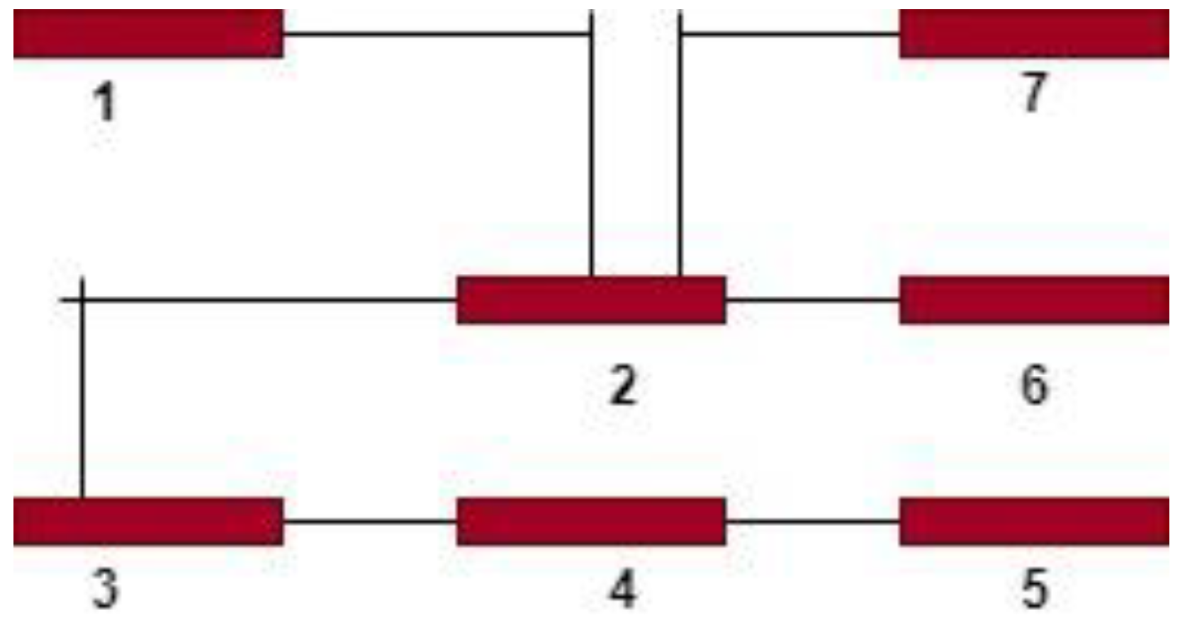
2.1. Fundamental Optimal PMU Placement Modelling

This is the basic approach that provides the initial material of the OPP problem. For the placement of PMUs at any specific busbar by utilizing any IEEE power network, a binary numbering phenomenon is used to decide the preferable places. To make this concept more understandable an OPPP is initialized by the basic linear integer programming for an n-bus system.
h i = { 1     if   PMU   is   placed   at   bus   i   0     otherwise }
m i n i = 1 n q j   . h j
Subject to the constraints:
B h 1
The   entries   of   the   h j   are   ( 0   and   1 )
where, in the present research the q j is supposed to be the cost factor of PMU installation at any b u s   j in the network and its value is assumed as 1 per unit. Furthermore, B is defined as the binary connectivity matrix of the N × N network whose entries are nonzero. The entries are obtained by incident matrix as shown in the Equation (5).
B i , j = { 1 i f   i = j 1 i f   i   c o n n e c t e d   t o   j 0 o t h e r w i s e }
Here is an example of 7 bus IEEE-test system with the defined binary connectivity matrix and its constraint functions are illustrated in Figure 1.
With the help of Equation (5) the matrix B can be generated by converting these entries into binary numbers (0 and 1).
B = [ 1   1   0   0   0   0   0 1   1   1   0   0   1   1 0   1   1   1   0   0   0 0   0   1   1   1   0   0 0   0   0   1   1   0   0 0   1   0   0   0   1   0 0   1   0   0   0   0   1 ]
The constraint function for this system can be written as:
f ( X ) = [ f 1 = x 1 + x 2 f 2 = x 1 + x 2 + x 3 + x 6 + x 7 f 3 = x 2 + x 3 + x 4 f 4 = x 3 + x 4 + x 5 f 5 = x 4 + x 5 f 6 = x 2 + x 6 f 7 = x 2 + x 7 ] 1
The constraint functions are expressed from connectivity matrix B . Consider an example of f 1 that represents the observability for bus 1. In which x 1 + x 2 are selected just because these two nodes are related to each other and only these nodes can make node 1 observable. Other nodes are not considered because of the disjunction between them.

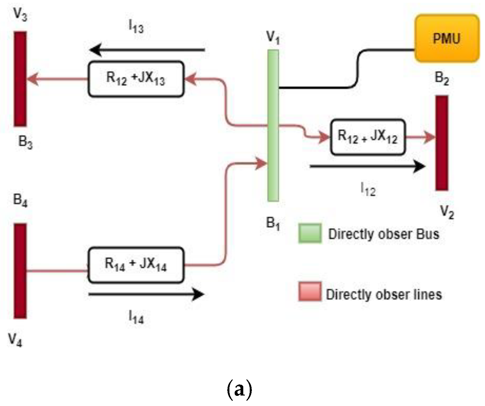
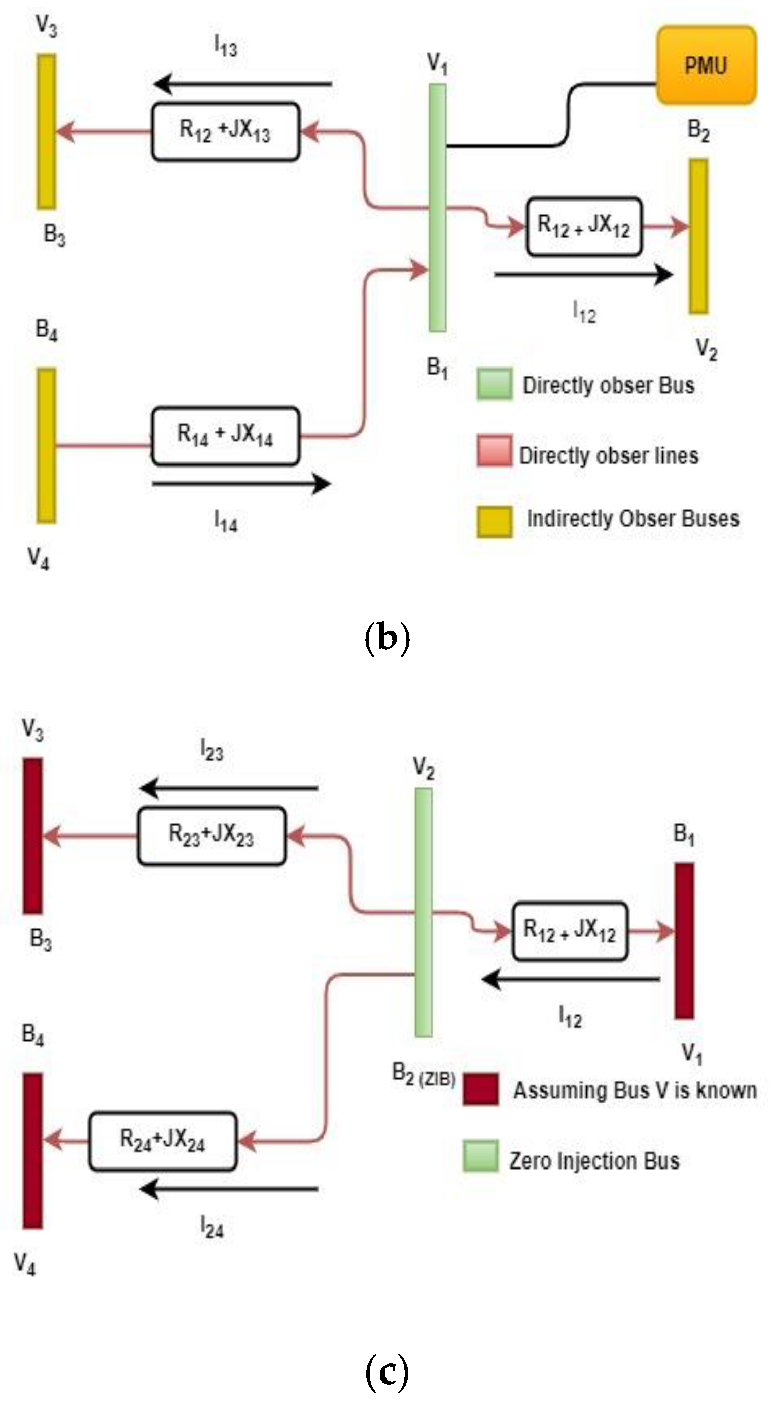
2.2. Observability Analysis Using PMUs

  • A bus with installed PMU is observed directly.
  • A bus adjacent to PMU installed bus can be observed through Ohm’s law.
  • If only one bus is unobservable, and rest of the incident buses are observed so the remaining one will be measured by KCL and KVL.
  • These rules are thoroughly explained in the visual representation as shown in Figure 2 [11].
Observability rule 1 explains how voltage phasor of the installed PMU bus and branches can be directly measured so the values of V 1 , I 12 , I 13 ,   a n d   I 14   can be measured directly by PMU.
According to rule 2, the corresponding lines adjacent to the installed PMUs bus are observable which are current phasors, I 12 , I 13 , a n d   I 14 . Since V 1 is already known so the remaining voltage phasors at V 2 , V 3 , and V 4 of the uninstalled PMUs bus can be calculated using ohm’s law given in Equations (8)–(13) [12].
I 12 = V 1 V 2 R 12 + J X 12
V 2 = V 1 I 12 ( R 12 + J X 12 )
I 13 = V 1 V 3 R 13 + J X 13
V 3 = V 1 I 13 ( R 13 + J X 13 )
I 14 = V 1 V 4 R 14 + J X 14
V 4 = V 1 I 14 ( R 14 + J X 14 )
These mathematical equations are derived from the standard Ohm’s law while considering the observability rule 2 in Figure 2b, which describes that if the current phasors of all the branches are known with one directly observable voltage phasor, then the remaining voltages lines can be obtained using generic formulas.
Conferring to rule 3. If there are buses adjacent to an unobserved ZIB, all are observable. So, the ZIB that is B-2 in the observability rule 3 case can be calculated by applying KCL and KVL. The remaining V 2 and I 12 , I 23 ,   I 24 which is the parameters of ZIB can be calculated as [12]:
V 2 = V 1 I 12 ( R 12 + J X 12 )
V 2 = V 3 I 23 ( R 23 + J X 23 )
V 2 = V 4 I 24 ( R 24 + J X 24 )
0 = I 12 I 23 I 24
The voltage phasor and current phasor on the unidentified ZIB can be estimated by the above given equations. Since V 2 is the unknown parameter in rule 3 a modelling of ZIB, here V 2 can be derived using the above-mentioned equations from Equations (14)–(17). These all constraint functions and equations lead to the optimum placement of PMU, minimizing the number of PMU.

2.3. IEEE-Networks Data

The proposed work is tested using the material of IEEE-bus networks which are taken from the MATPOWER toolbox. All the characteristics of test systems are tabulated in the given Table 1 and Table 2.
MATLAB R2014b software is used to implement the proposed work with the specified computer core™ i3-3110M CPU @ 2.40 GHz with a 4-GB installed RAM. MATLAB software is the fundamental material in this case which is used to generate the proposed model and algorithm code for the OPP problem. The features of IEEE-bus networks are tabulated in the given Table 1 and Table 2. The above two tables describe the external and internal characteristics of IEEE-bus networks. In which the material of the proposed work is taken from these standard bus-networks based on the bus’s connection, maximum number of lines connected to a single bus, and maximum degree of indexes. Furthermore, the internal characteristics of a system has generator buses, load buses, radial, and ZIBs so these materials are much more useful when considering OPP problem. Table 1 consists of overall network connectivity whereas Table 2 includes bus-bars incoming and outgoing power flows and power injections. The simulations are done through the available materials while considering the existing gap in prior studies.

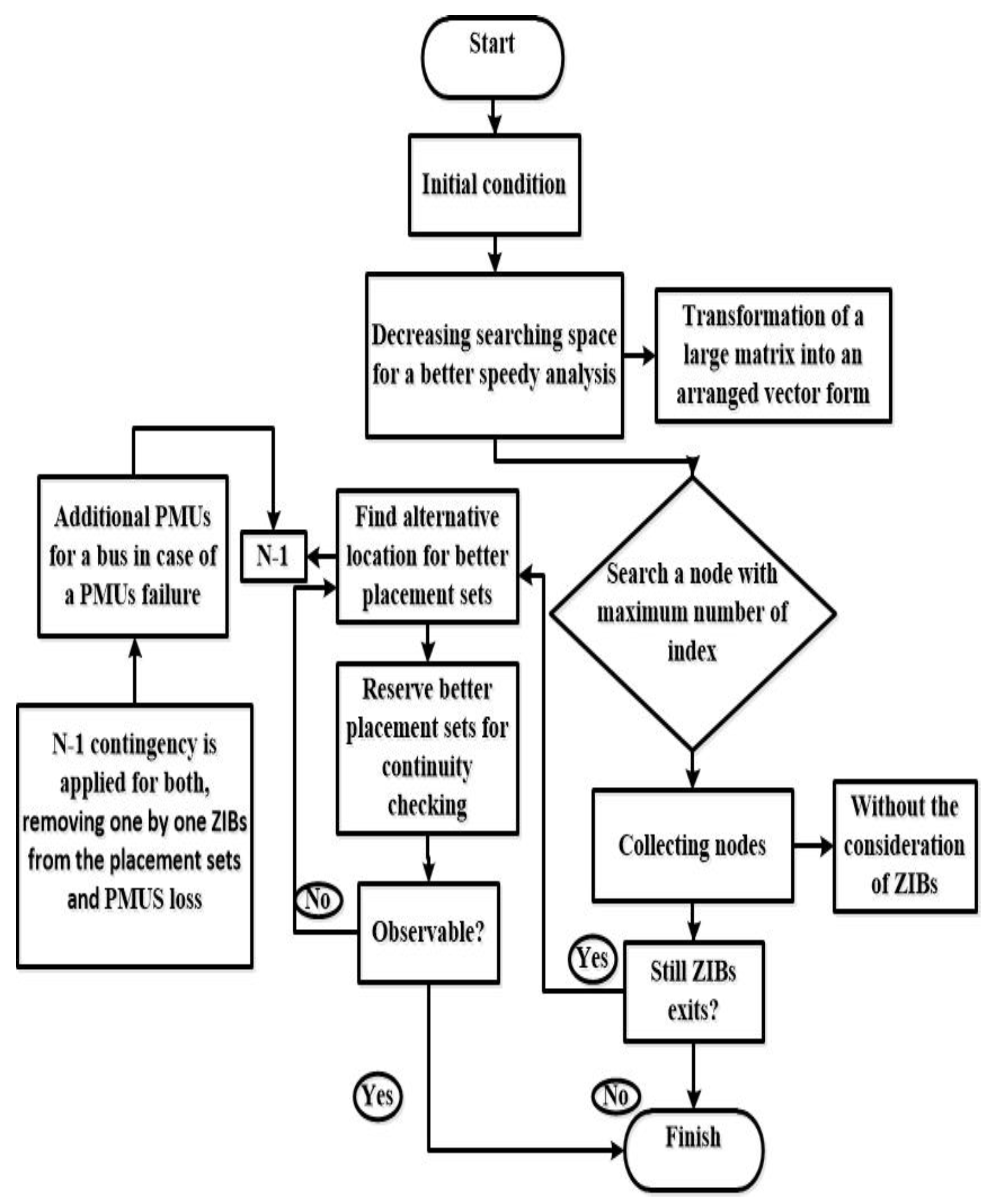
2.4. Proposed Method

A novel work is proposed on the elementary material based OPP problem formulation. This work is considering reduction approach of ZIBs from the optimum location, finding the alternative locations for PMUs failure at main point and to identify the channels limits of PMUs. The critical PMUs failure contingency is applied after getting the complete set of PMUs in any network. Further, during the operation of the proposed technique, first it randomly selects the optimum locations including ZIBs based on maximum degrees of index. Afterwards, an additional alternate pattern is followed by presentation of approach in which it operates continuously until the desired placement sets are obtained with the removal of pure transit nodes. Moreover, if any of the bus in the placement model is a radial bus, then the function does not consider it in a followed pattern. It is a policy of optimum PMU placement problem that needs to only allocate small number of PMUs in a network. Radial bus refers to a bus in a network that has only a single neighbor incident branch connected to it. Whereas, if a PMUs is placed at a radial bus then enlarged number of PMUs will be required in this context so maximum number of observations on a bus will be constrained. Let us assume, if a PMUs has unlimited number of channels it is better to select a bus with higher number of degrees. Thus, it can give better network coverage rather than placing on a radial bus.
The channel limits mainly explain the required number of PMUs in a network. It is further stated that when a PMU has additional number of channels, it can cover the greater number of nodes in a network which directly reduces the required number of PMUs. Suppose, if a single PMU has a greater number of channels or incident branches connected to the installed PMU node, it can be directly proportional to minimize the actual number of PMUs. Additionally, for a speedy analysis a topology-based observability rule is applied at the stage when a system generates binary adjacent matrix. Specifically, the matrix gets squeezed for a better resultant finding when there is a need of faster response. The large data matrixes are compressed using symmetric Cuthill Mckee-Permutaion which rearrange the elements and then converts it into vector form by getting the nonzero elements. Moreover, the effectiveness of the proposed work is verified on the IEEE-9, -14, -24, - 30, - 57, -118, and a New England 39-test system using MATLAB R2014b software. All these similar IEEE-datasets are taken in the proposed work in order to make proper benchmarking with previous literatures as these all are already applied for the validation and authentication of their work. Whereas, the enlarged number of IEEE-dataset taken in proposed design will surely provide an insight benefit to the researcher when considering multi-objectives task on OPPP. The operation of proposed work is explained in the flow chart Figure 3. Whereas, when the main program gets started it gives an initial solution for the OPP problem which is listed in the given Table 3.
The flow chart represents the complete cycle of the proposed method which follows the basic vision of the removal of ZIBs from the optimal location and makes sure the network optimum placement sets are completely free from the pure transit nodes. The operation is divided into two rounds: initial and final stage. If the initial stage fails in achieving the desired outcomes, this method is further operated for the final process because in initial stage the algorithm is quite slow to perform its operation because of the complexities in programming. In initial stage the basic material of OPP problem formulation is applied through the derivation of matrix B and constraint functions using the single line diagrams which helps in knowing the existence of binary digits in the preferable places. Afterwards, three observability analysis rules are applied using the KCL, KVL, and ohm’s law. The observation of the excluded ZIBs in the placement sets are done by the nearby incident buses using KCL and KVL equation listed above in the material section. The proposed method determines the length of matrix B, if the length is large and have unimportant element so it is reversed by symmetric Cuthill Mckee-permutaion in order to find ZIBs. It reduces the searching spacing for a faster response of algorithm, which additionally searches a node with maximum indexes or branches. To obtain the system-free ZIBs, the busbars are divided into different candidates features such as length, best candidate, best location of candidate, and ignoring the worst candidate location. After every iteration, the program stores the placement sets of best candidate locations then removes the ZIBs one by one at every cycle of algorithm in order to distribute PMUs in the explored place. Furthermore, the algorithm finds system’s observability with the help of repeating and finding alternative commands by storing the candidate previous and current placement sets. This new approach is applied after performing several tests on the previous techniques to fulfill the existing gap; however, they do not provide effective results in getting the desired objective which led to generate a new design approach. Moreover, the N 1 contingency PMU malfunction and channel limits is done through mathematical modelling using IEEE-single line diagram. For a channel limitation an equation is derived which produces the number of possible combination of branches as shown in Equation (18) [12].
A F j = { A C j I f   Y A T j 1 A T j < Y
where Y represents the channel limits and A F i shows the possible combinations related to branches of b u s   j , whereas A T i is the number of incidents to a b u s   j and A C j is the possible combination of Y out of number of incident. From the give Equation (18), it is quite clear that if the channel limits Y of any PMUs is greater that the number of combinations related to the branches A F j then one PMU is enough to observe all the incident branches connected to a installed PMU b u s   j .

3. Results and Discussion

The proposed technique has been discussed in detail in the previous section where solving the OPP problem using different objectives are emphasized. In order to verify the application of proposed work it is tested on several IEEE-bus networks starting from bus-9, -14, -24, -30, -39, -57 to 118. IEEE-network data are obtained from the standard MATPOWER site and implemented on MATLAB R2014b. Different cases are considered for the proposed approach followed by initial and final solution for the exclusion of pure transit node, single PMU failure, and PMU’s channel limits. Further, the PMUs is prevented from being allocated on the radial bus and does not take it as an optimum location. Rather, the nearby radial bus is suggested for the placement of PMU. The main aim of proposed method is to minimize the actual number of PMUs and maximize measurement redundancy of the network by exclusion of the ZIBs, PMUs loss, and PMUs channel limits. To achieve this, the simulation is carried out on two approaches, starting and final solutions. All the data of initial results are entered in Table 3 which is further explained in the same section. Besides, Table 4 illustrates the validity and effectiveness of proposed technique of final results. As it is evident that the proposed technique completely succeeded in removing the pure transit node from the optimum places. Whereas, the remaining Table 5 proves the simulation results and Table 6 and Table 7 provide the best outcomes of PMUs loss and PMUs channel limits.
As it can be seen in the given Table 3, the obtained initial solution somehow successfully removed the ZIBs, but the main purpose is to completely clear the whole system from ZIBs. It is clearly illustrated in the Table 3, in which during preliminary outcomes the proposed technique completely outperformed up to the mark and exterminated all the pure transit node in a few test cases such as, 14, 24, and 30-bus network. However, the inaccuracy of the initial solution has been noticed when it operates for a very small bus network-9 which has very fewer number of busses with a single ZIB. Even though, at this stage it is considering ZIBs as an optimum location which has been filtered during alterative stage by the proposed approach. In addition, for a larger system it chooses ZIBs as an optimum location because the number of PMUs become higher. First, the operation is fixed at which the PMU needs to be placed on a heavily loaded areas such as generator bus, PV or PQ loaded bus. In Table 3, when taking an example of IEEE-14 bus network, it consists of six generator busses. So, during the initial operation, the algorithm takes three generator buses for the optimum locations and same goes for the remaining test system. The increasing number of buses are directly proportional to the increasing number of demanded PMUs. For a complete observable system, it is stated in the existing literatures that almost 20-30% number of PMUs are required to install at any bus network [20]. Although, the initial solution is rectified to certain extent such as CPU time, number of PMUs, and location of PMU. Thus, the best outcomes are obtained in the final stage which are given in the Table 4.
Moreover, Table 5 is used to differentiate the results between proposed method and previous techniques. Whereas, these tabulated results are only used for the optimum locations of PMUs and comparing the quantity of PMUs.
The final solution is taken into the consideration because of the lack of performance in initial stage. The proposed work is divided into two parts, first, it is supposed to get the optimum locations without consideration of ZIBs from all the included busses in the system. If the process does not provide meaningful result, then operation is further extended to the final solution, in which it is not only operated for the exclusion of ZIBs, but also optimizes the greater number of locations and enhances the algorithm time. For removing every ZIBs from the placement sets after the initial solution a method is used to improve the searching space of a proposed algorithm. A symmetric Cuthill Mckee-permutaion technique is used to ordering the elements in the matrixes and reversing the length of large matrix elements into a vector form for better analysis. It is another function that only selects the non zeros digits which further helps in eliminating the pure transit nodes. These all processes are used for the purpose of benchmarking with present studies about OPP problem. The simulated results are tabulated in the given Table 4 in which it is noticeably observed that there is no pure transit node in the placement sets. For instance, existing most popular techniques such as genetic algorithm and particle optimization swarm which have operated for the same OPP problem even could not provide the authentication results with the hybrid approaches. Few of them do not have the availability of proper data when considering for the OPPP benchmarking. As it can be seen in the Table 5 that there is a clear amendment in minimum number of PMUs requiring across all the IEEE-test systems, except the outcomes is either symmetrical for larger test-system.

Effect of Channel Limit and Single PMUs Malfunction

Power system consists of sensitivity in all three parts of a network, any uncertainty event may happen can cause huge catastrophic failure. Particularly when it comes to the fault or malfunction of any device. Symmetrical as a PMU, it is a metering device installed across the particular busses to monitor and observe the behavior of a system. If one of the devices become malfunctioned, then the monitored bus gets affected and will remain unobservable. With respect to the OPP problem, a PMU loss must be considered in order to maintain the observability of the electrical network [21]. In this contingency every bus can be observed by at least two PMUs. It is more supportive in providing backup for the busses to monitor if any of the PMUs from the placement set gets out of function. The result of single PMU malfunction is presented in Table 6. Furthermore, when considering the channel limits constraint, most literatures assume that a single PMUs has unlimited number of channels. Although, in practical scenario industries manufacture a design which has a limited number of channels [22]. In case of considering channel limits, suppose the single line diagram of 14-bus network, as shown in IEEE, interconnected 14-bus network, Figure 4, in which bus-4 has five number of branches. In this context if bus-4 needs to observe by a single PMUs, it must have 6 number of channels to measure voltage phasor of bus-4 and 5 branch currents i.e., {4-2, 4-3, 4-5, 4-7, 4-9}.
This is the IEEE-14 bus network with specified parameters. The dark rectangular shaped with labeled numbering denotes the busbars with incidents lines coming and outgoing to it. Furthermore, the round orange circle attached with busbars shows the generation buses and yellow circle represents the radial bus. The rest of the buses without orange and yellow labeled are load buses [Source from MATPOWER].
Table 6 explains the total network observability when considering single PMU loss. The number of required PMUs increase when every bus is observed by at least two PMUs, in other words two PMUs are accountable for only one bus to monitor and observe. These number of PMUs are taken as an optimal, and minimization in the quantity ensures the complete system observability. As it can be noticed that a greater number of PMUs will be needed in this case when comparing the results to the exclusion of pure transit node and channel limits. As there are large number of radial buses those have only one neighboring branches. In order to make it observable double time a PMU must be needed to place on its neighboring branch and radial bus itself which is a reason of the increasing number of PMUs in every network. The obtained result is compared with recent studies which confirms the better simulation result provided by the proposed work.
The key purpose of a proposed approach is to identify a current gap and implement a new design which can operate for a multi-task objective. The obtained results determine the optimum locations without pure transit nodes and minimum number of PMUs in every possible combinations of PMUs channel limits. This identified gap will help in future work to the power engineers and researchers when they consider the same OPP problem, in fact it will be beneficial for economic perspectives, saves time and extra efforts. Additionally, the current limitations of the proposed design are IEEE-data set from MATPOWER implemented on MATLAB, which will be extended to a large IEEE-datasets and can be useful when consider it in real life practical contingencies such as smart grids, conventional distribution power stations. For cases considering channel limits, the number of PMUs is obtained for every channel and compared with current studies which is presented in Table 7. Whereas, the range of channel is set up to five limitations starting from 2–5. Limited number of channels confined the measurement of branch currents. That is why it is observed during the operation of channel limits 2 that lesser number of PMUs can measure small amount of branch currents. Thus, in case of consideration of channel limits if PMUs consist of an additional number of channels, a network will be examined by a small number of PMUs. Otherwise, during limited channels the system will experience large number of PMUs to be required to cover the whole network. It is clearly illustrated in the Table 7 that a greater number of PMUs channels provide lesser number of PMUs.

4. Conclusions

This paper presented a new technique for the optimum placement of PMUs for complete network observability. The operation of proposed method is based on a symmetry topological observability. For determining the OPP problem, multiple objectives are taken into the account such as initial and final solution technique is used to eliminate all the pure transit node from the optimum locations, case considering PMUs loss and channel limits. Prior literatures have taken ZIBs in all their simulation results which has no benefit to select it as an optimum location, as there is no power injection and zero power flows through it. The validation of proposed work is compared with the existing studies output which shows the minimum number, optimum locations in all cases of OPP problem. Moreover, simulated results of cases considering PMUs loss and channel limits are slightly enhanced from the previous techniques. Whereas, it can be noted that during both cases the symmetrical outcomes are obtained after several simulation run in large IEEE-networks.

Author Contributions

Conceptualization, N.B.M.N., M.B., and M.A.S.; formal analysis, M.B.; supervision, N.B.M.N.; methodology, M.A.S.; software, M.I., M.B.; validation, M.T., M.A.S., M.B.; writing original draft, M.B.; review and editing, N.B.M.N., M.A.S. All authors have read and agreed to the published version of the manuscript.

Funding

The authors thank the financial support by Universiti Teknologi PETRONAS (UTP) for this work and the research was funded by YUTP cost center (Ref: 0153AA-E93) from UTP.

Conflicts of Interest

The authors declare no conflict of interest.

References

  1. Chatterjee, S.; Kr, B.; Roy, S.; Ghosh, P.K. Optimal Placement of PMU Considering Practical Costs in Wide Area Network. In Proceedings of the 2017 14th IEEE India Council International Conference (INDICON), Roorkee, India, 15–17 December 2017. [Google Scholar]
  2. Martin, K.E.; Benmouyal, G.; Adamiak, M.G.; Begovic, M.; Burnett, R.O.; Carr, K.R.; Cobb, A.; Kusters, J.A.; Horowitz, S.H.; Jensen, G.R.; et al. IEEE standard for synchrophasors for power systems. IEEE Trans. Power Deliv. 1998, 13, 73–77. [Google Scholar] [CrossRef]
  3. Dua, D.; Dambhare, S.; Gajbhiye, R.K.; Member, S.; Soman, S.A. Optimal Multistage Scheduling of PMU Placement: An ILP Approach. IEEE Trans. Power Deliv. 2008, 23, 1812–1820. [Google Scholar] [CrossRef]
  4. Boisen, M.B. Power system observability with minimal phasor measurement placement—Power Systems. IEEE Trans. Power 1993, 8, 707–715. [Google Scholar]
  5. Xu, B.; Abur, A. Observability Analysis and Measurement Placement for Systems with PMUs. In Proceedings of the IEEE PES Power Systems Conference and Exposition, 2004, New York, NY, USA, 10–13 October 2004; pp. 2–5. [Google Scholar]
  6. Chakrabarti, S.; Venayagamoorthy, G.K.; Kyriakides, E. PMU placement for power system observability using binary particle swarm optimization. In Proceedings of the 2008 Australasian Universities Power Engineering Conference, Sydney, NSW, Australia, 14–17 December 2008. [Google Scholar]
  7. Mohammadi-Ivatloo, B. Optimal placement of PMUs for power system observability using topology based formulated algorithm. J. Appl. Sci. 2009, 9, 2463–2468. [Google Scholar] [CrossRef]
  8. Chakrabarti, S.; Kyriakides, E. Optimal Placement of Phasor Measurement Units for Power System Observability. IEEE Trans. Power Syst. 2008, 23, 1433–1440. [Google Scholar] [CrossRef]
  9. Chen, J.; Member, S.; Abur, A. Improved Bad Data Processing via Strategic Placement of PMUs. In Proceedings of the IEEE Power Engineering Society General Meeting, 2005, San Francisco, CA, USA, 16 June 2005; pp. 1–5. [Google Scholar]
  10. Chen, J.; Member, S.; Abur, A. Placement of PMUs to Enable Bad Data Detection in State Estimation. IEEE Trans. Power Syst. 2006, 21, 1608–1615. [Google Scholar] [CrossRef]
  11. Sun, L.; Chen, T.; Chen, X.; Ho, W.K.; Ling, K.V.; Tseng, K.J.; Amaratunga, G.A. Optimum Placement of Phasor Measurement Units in Power Systems. IEEE Trans. Instrum. Meas. 2019, 68, 421–429. [Google Scholar] [CrossRef]
  12. Hanis, N.; Rahman, A.; Zobaa, A.F. Binary PSO Algorithm for Optimal PMUs Placement. IEEE Trans. Ind. Inform. 2017, 13, 3124–3133. [Google Scholar]
  13. Xu, P.; Wollenberg, B.F. Power System Observability and Optimal Phasor Measurement Unit Placement. 2015 Department of Electrical and Computer Engineering College of Science and Engineering University Minnesota Twin Cities. IET Gener. Transm. Distrib. 2015, 9, 1–55. [Google Scholar]
  14. Azizi, S.; Dobakhshari, A.S.; Member, S.; Sarmadi, S.A.N. Optimal PMU Placement by an Equivalent Linear Formulation for Exhaustive Search. IEEE Trans. Smart Grid 2012, 3, 174–182. [Google Scholar] [CrossRef]
  15. Marín, F.J.; García-Lagos, F.; Joya, G.; Sandoval, F. Optimal Phasor Measurement Unit Placement using Genetic Algorithms. In Lecture Notes in Computer Science, Proceedings of the International Work-Conference on Artificial Neural Networks, 2–4 June 1999; Springer: Berlin/Heidelberg, Germany, 2007; pp. 486–493. [Google Scholar]
  16. Peng, J.; Sun, Y.; Wang, H.F. Optimal PMU placement for full network observability using Tabu search algorithm. Int. J. Electr. Power Energy Syst. 2006, 28, 223–231. [Google Scholar] [CrossRef]
  17. Hajian, M.; Ranjbar, A.M.; Amraee, T.; Shirani, A.R. Optimal placement of phasor measurement units: Particle swarm optimization approach. In Proceedings of the 2007 International Conference on Intelligent Systems Applications to Power Systems ISAP, Toki Messe, Niigata, Japan, 5–8 November 2007. [Google Scholar]
  18. Gomez-Exposito, A.G.; Abur, A. Power System State Estimation: Theory and Implementation; CRC Press: Boca Raton, FL, USA, 2004; Volume 9, pp. 101–108. [Google Scholar]
  19. Zhong, J. Phasor Measurement Unit (PMU) Placement Optimisation in Power Transmission Network based on Hybrid Approach; RMIT University: Melbourne, Australia, 2012. [Google Scholar]
  20. Theodorakatos, N.; Manousakis, N.M.; Korres, G. Optimal PMU Placement Using Nonlinear Programming. arXiv 2015, arXiv:1507.05258. [Google Scholar]
  21. Theodorakatos, N.P.; Manousakis, N.M.; Korres, G.N. A sequential quadratic programming method for contingency-constrained phasor measurement unit placement. Int. Trans. Electr. Energy Syst. 2015, 25, 3185–3211. [Google Scholar] [CrossRef]
  22. Veilumuthu GV, R.; Theresa, P.A. Optimal PMU placement and observability of power system using PSAT. Int. J. Comput. Commun. Inf. Syst. (IJCCIS) 2012, 2, 67–71. [Google Scholar]
  23. Reddy, K.S.; Rao, D.A.K.; Kumarraja, A.; Varma, B.R.K.; Scholar, M.E.; College, S.E. Implementation of Integer Linear Programming and Exhaustive Search Algorithms for Optimal PMU Placement under Various Conditions. In Proceedings of the 2015 IEEE Power, Communication and Information Technology Conference (PCITC), Bhubaneswar, India, 15–17 October 2015; pp. 1–5. [Google Scholar]
  24. Maji, T.K.; Acharjee, P. Multiple Solutions of Optimal PMU Placement Using Exponential Binary PSO Algorithm for Smart. IEEE Trans. Ind. Appl. 2017, 53, 2550–2559. [Google Scholar] [CrossRef]
  25. Korkali, M.; Member, S.; Abur, A. Placement of PMUs with Channel Limits. In Proceedings of the 2009 IEEE Power & Energy Society General Meeting, Calgary, AB, Canada, 26–30 July 2009; pp. 1–4. [Google Scholar]
  26. Yuehui, C.; Haiyan, C.; Jinfu, C.; Xianzhong, D. An Improved Particle Swarm Optimization Algorithm for Multistage and Coordinated Planning of Transmission Systems. In Proceedings of the 2005 IEEE/PES Transmission & Distribution Conference & Exposition: Asia and Pacific, Dalian, China, 18 August 2005. [Google Scholar]
  27. Djurovi, I.; Vujŏ, I. Optimal placement of PMUs with limited number of channels. Electr. Power Syst. Res. 2012, 90, 93–98. [Google Scholar]
  28. Wihartiko, F.D.; Wijayanti, H.; Virgantari, F. Performance comparison of genetic algorithms and particle swarm optimization for model integer programming bus timetabling problem. IOP Conf. Ser. Mater. Sci. Eng. 2018, 332, 012020. [Google Scholar] [CrossRef] [Green Version]
Figure 1. IEEE-7-Buess network.
Symmetry 12 01174 g001
Figure 2. (a). Observability rule 1. Modelling; (b). Observability rule 2. Modelling; (c). Observability rule 3 modelling (ZIB).
Symmetry 12 01174 g002aSymmetry 12 01174 g002b
Figure 3. Flow chart of removing the pure transit for the optimum placement of phasor measurement unit (PMU).
Symmetry 12 01174 g003
Figure 4. Interconnected IEEE-14 bus network [25].
Symmetry 12 01174 g004
Table 1. Attributes of the network system [13].
IEEE-Bus NetworkNo. of Connected LinesMaximum Lines Connected to a BusMaximum Degrees of Bus
9-bus934
14-bus2054
24-bus3859
30-bus4176
39-bus46516
57-bus8069
118-bus1861249
Table 2. Characteristics of buses [13].
Test SystemGenerator BusesLoad BusesReference BusesPure Transit Nodes
9-bus3313
14-bus5811
24-bus111314
30-bus62416
39-bus1020110
57-bus745114
118-bus5478110
Table 3. Initial solution of proposed work obtained for optimum placement of PMU problem (OPPP).
Test CasesNo. of PMUs
N P M U
Locations of PMUsLocation of ZIBs in Placement SetLocation of ZIBs in Test-CasesCPU Time in Seconds (s)
9-bus network34, 7, 944, 6, 80.31105
14-bus network48, 3, 5, 11-70.21095
24-bus network71, 7, 22, 10, 9, 15, 14-11, 12, 17, 240.7826
30-bus network71, 5, 16, 13, 10, 15, 19-6, 9, 22, 25, 27, 281.405
39-bus network132, 13, 15, 17, 19, 22, 24, 26, 34, 36, 37, 38, 392, 13, 17, 19, 222, 5, 6, 10, 11, 13, 14, 17, 19, 223.22
57-bus network142, 10, 13, 17, 19, 16, 24, 29, 30, 32, 38, 50, 54, 56247, 11, 21, 22, 24, 26, 34, 36, 37, 39, 40, 45, 46, 486.218
118-bus network392, 117, 7, 14, 11, 10, 19, 36, 29, 115, 17, 21, 43, 37, 32, 25, 59, 53, 62, 58, 41, 57, 73, 46, 110, 105, 49, 70, 118, 78, 80, 95, 100, 102, 93, 91, 82, 89, 84375, 9, 30, 37, 38, 63, 64, 68, 71, 8121.4111
Table 4. Alternative/final solution of proposed work obtained for OPPP.
Test Cases N P M U Locations of PMUsLocation of ZIBs in Test-CasesCPU Time in Seconds (s)
9-bus network22, 54, 6, 80.006
14-bus network22, 970.02132
24-bus network62, 3, 7, 10, 16 2111, 12, 17, 240.2324
30-bus network52, 3, 10, 12, 196, 9, 22, 25, 27, 280.3567
39-bus network71, 3, 16, 20, 23, 25, 292, 5, 6, 10, 11, 13, 14, 17, 19, 220.5334
57-bus network101, 13, 19, 29, 30, 32, 38, 51, 54, 567, 11, 21, 22, 24, 26, 34, 36, 37, 39, 40, 45, 46, 480.8455
118-bus network291, 12, 13, 19, 21, 25, 29, 32, 36, 41, 43, 46, 49, 53, 57, 59, 62, 70, 73,78, 80, 82, 85, 90, 92, 95, 101, 105, 110, 115, 1185, 9, 30, 37, 38, 63, 64, 68, 71, 811.0232
Table 5. Comparison of proposed work with current techniques.
TechniquesTest-Cases
9-Bus14-Bus24-Bus30-Bus39-Bus57-Bus118-Bus
Proposed work226571029
Genetic algorithm [14] N/A387N/A1229
Dual search [4], [15]N/A3N/AN/AN/AN/A29
Tabu search [16]N/A3N/AN/AN/A13N/A
Particle swarm optimization [17]N/A3N/A7N/A1128
Binary search algorithm [8]N/A3678N/AN/A
Binary particle swarm optimization [18]N/A3810811N/A
Greedy algorithm [19]N/A3N/A7811N/A
Branch and Bound algorithm [7]N/A3N/A791229
N/A: data is not available.
Table 6. PMU locations for single PMU failure.
Test Cases N P M U Proposed WorkExisting Techniques
Location of PMUs[12][23][24]
9-bus network61, 2, 3, 6, 8, 9N/A6N/A
14-bus network92, 4, 5, 6, 7, 8, 9, 10, 13999
24-bus network131, 4, 6, 7, 8, 10, 11,13, 14, 15, 17, 20, 211414N/A
30-bus network192, 3, 6, 7, 8, 9, 10, 12, 13, 15, 16, 19, 22, 23, 24, 25, 26, 27, 2921N/A20
39-bus network282, 3, 5, 6, 8, 9, 10, 12, 13, 15, 16, 19, 20, 22, 23, 25, 28, 29, 30, 31, 32, 33,34, 35, 36, 37, 38, 3928N/AN/A
57-bus network331, 3, 4, 6, 9, 11, 12, 13, 14, 17, 19, 20, 22, 24, 26, 28, 29, 30, 32, 33, 34, 36, 37, 38, 39, 41, 44, 47, 48, 50, 51, 53, 5633N/A33
118-bus network682, 3, 5, 6, 9, 10, 11, 12, 15, 17, 19, 21, 22, 24, 25, 27, 29, 30, 31, 32, 34, 35,68N/A69
37, 40, 42, 43, 45, 46, 49, 51, 52, 54, 56, 57, 59, 61, 62, 64, 66, 68, 70, 71,73,
75, 76, 77, 79, 80, 83, 85, 86, 87, 89, 90, 92, 94, 96, 100, 101, 105, 106, 108,
110, 111, 112, 114, 116, 117
Table 7. Case considering PMU channel limits.
Test-CasesChannel Limits, L Proposed Work
N P M U
Existing Techniques
[12][26][27][28]
9-bus network25N/AN/AN/AN/A
34N/AN/AN/AN/A
43N/AN/AN/AN/A
14-bus network277777
355555
444444
534444
24-bus network21212N/AN/AN/A
388N/AN/AN/A
477N/AN/AN/A
567N/AN/AN/A
30-bus network21515151515
31011111111
4910101010
5910101010
39-bus network21921N/AN/AN/A
31414N/AN/AN/A
41313N/AN/AN/A
51313N/AN/AN/A
57-bus network22929292929
31919191919
41717171717
51717171717
118-bus network263N/AN/AN/AN/A
342N/AN/AN/AN/A
436N/AN/AN/AN/A
536N/AN/AN/AN/A

