Dynamic Modeling and Vibration Characteristics Analysis of Transmission Process for Dual-Motor Coupling Drive System


Abstract
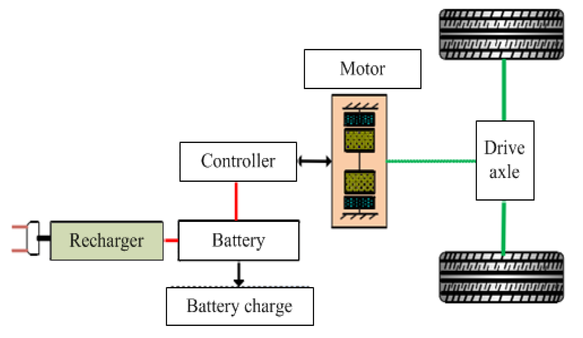
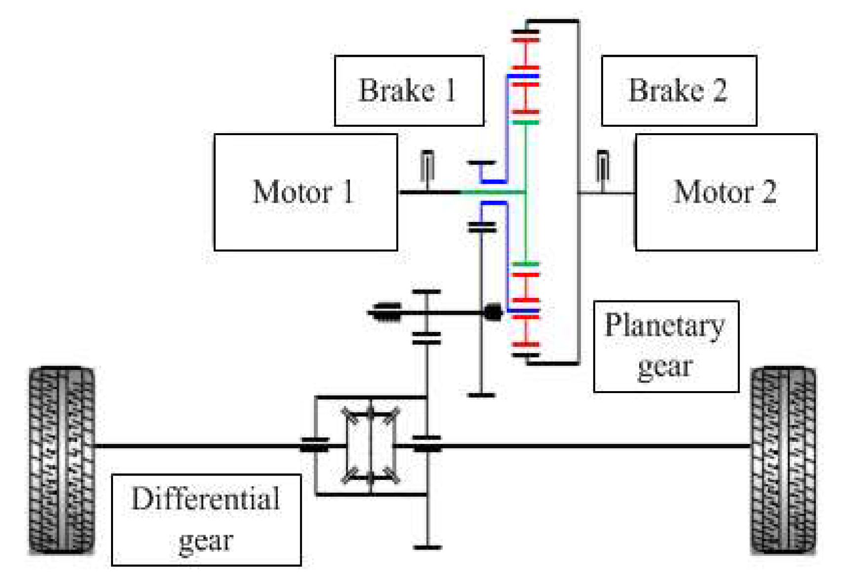
:1. Introduction
2. Dynamic Model of DCDS with TMM
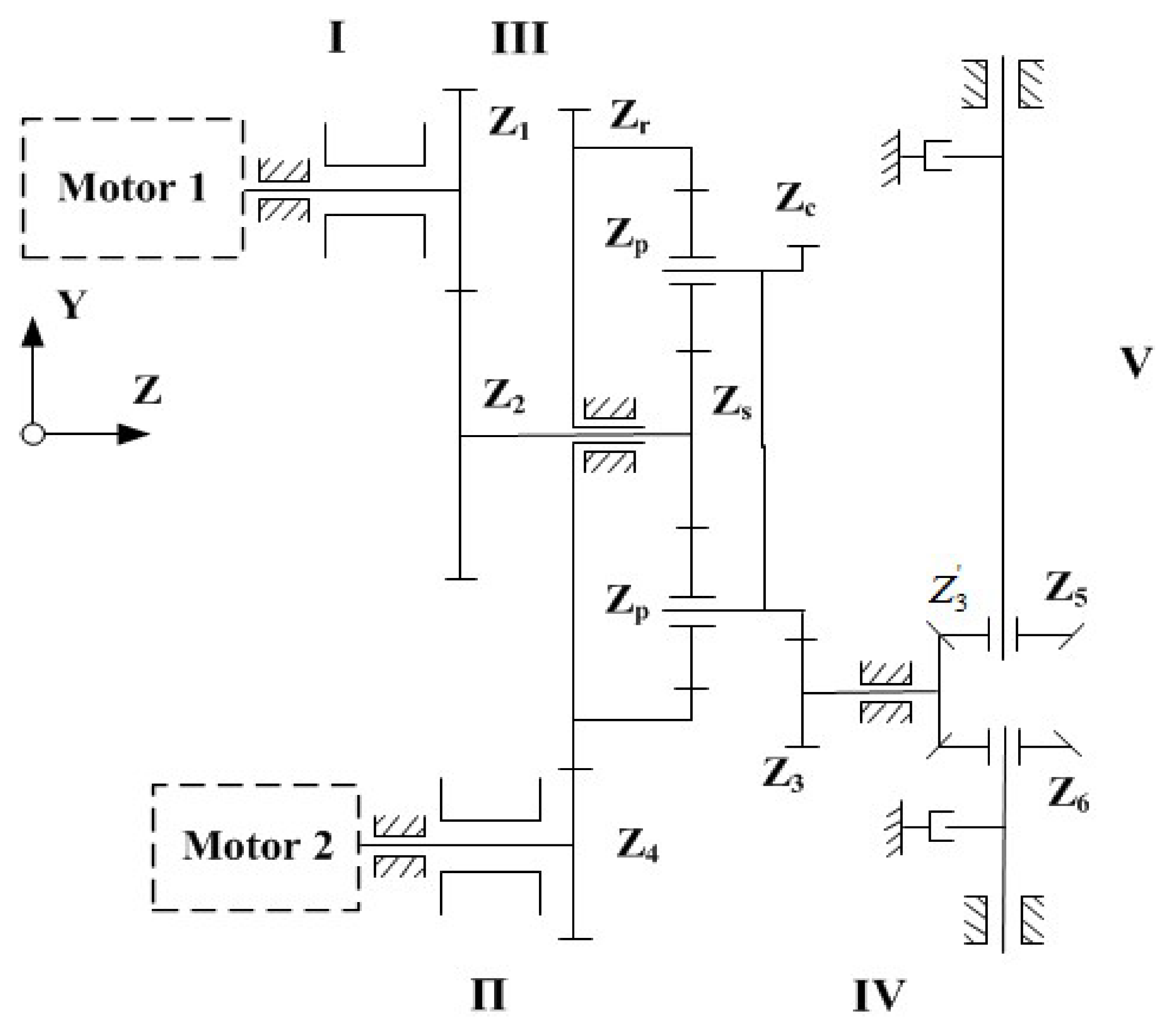
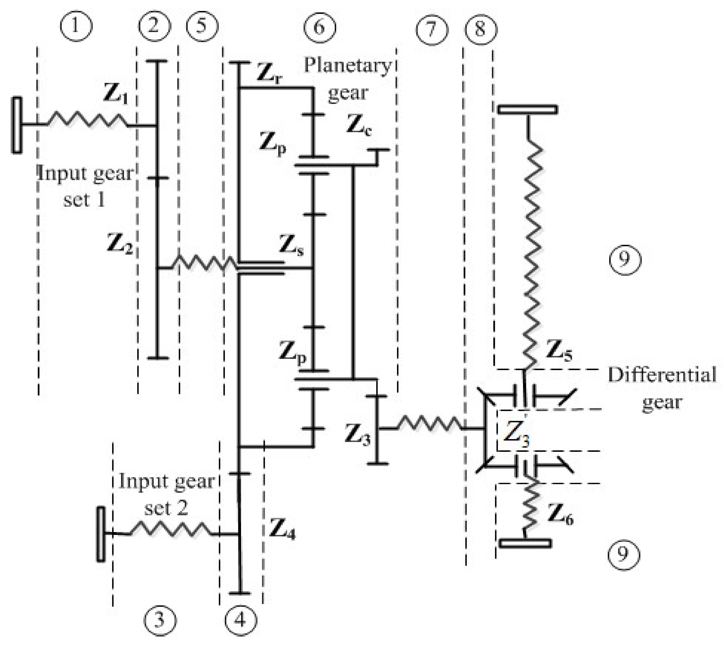
2.1. Establishment of the Model for the Whole DCDS
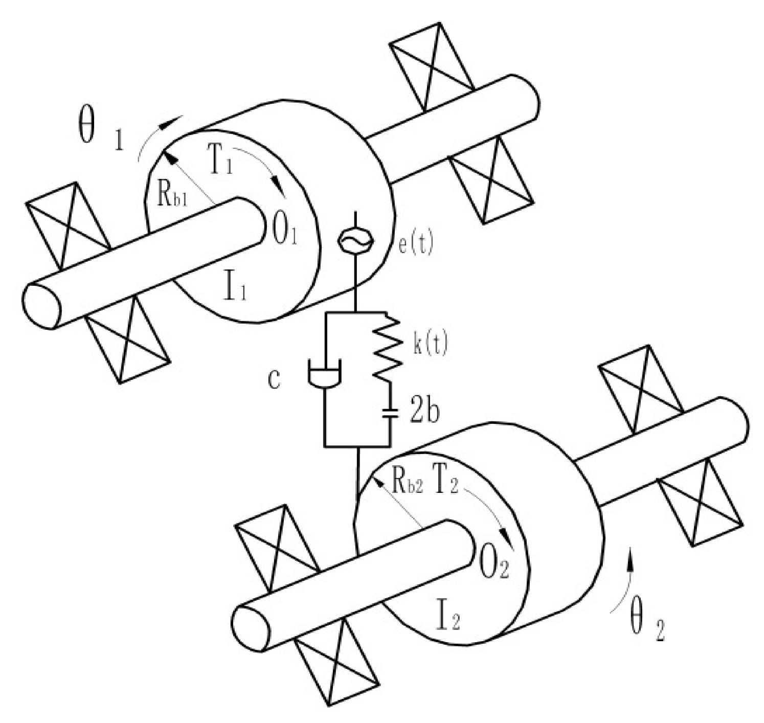
2.2. Modeling of Meshing Process for an Individual Pair of Gears
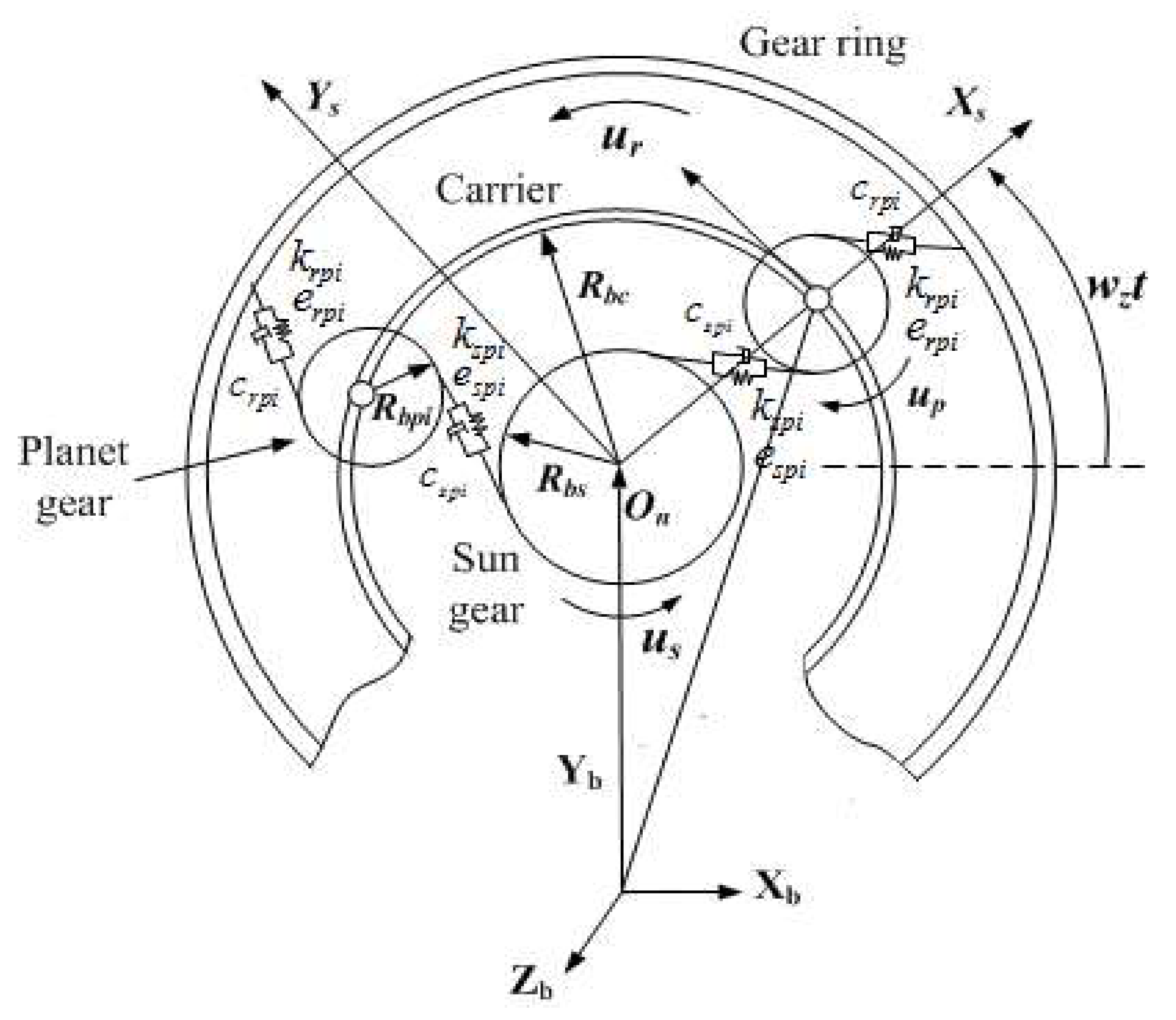
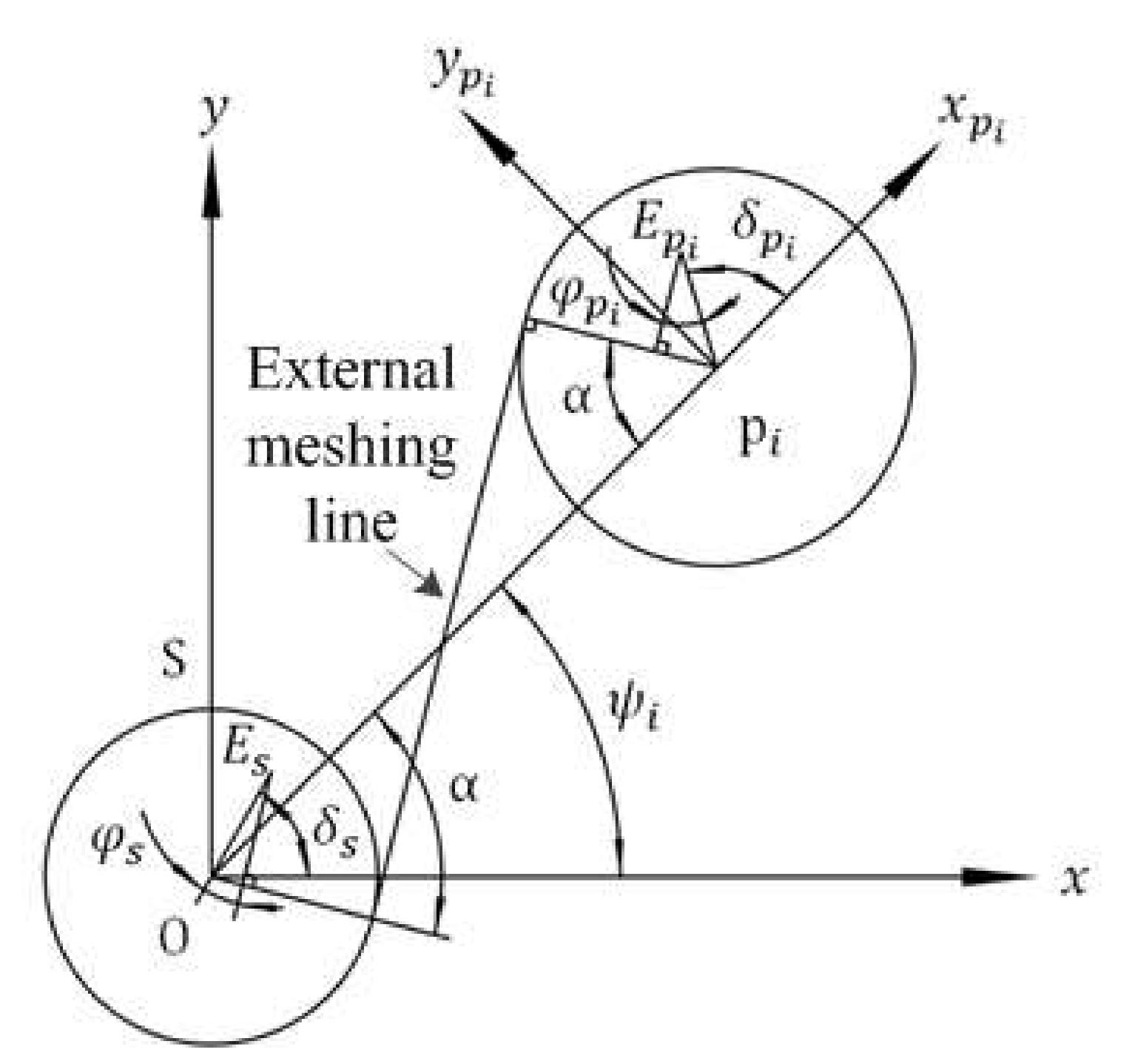
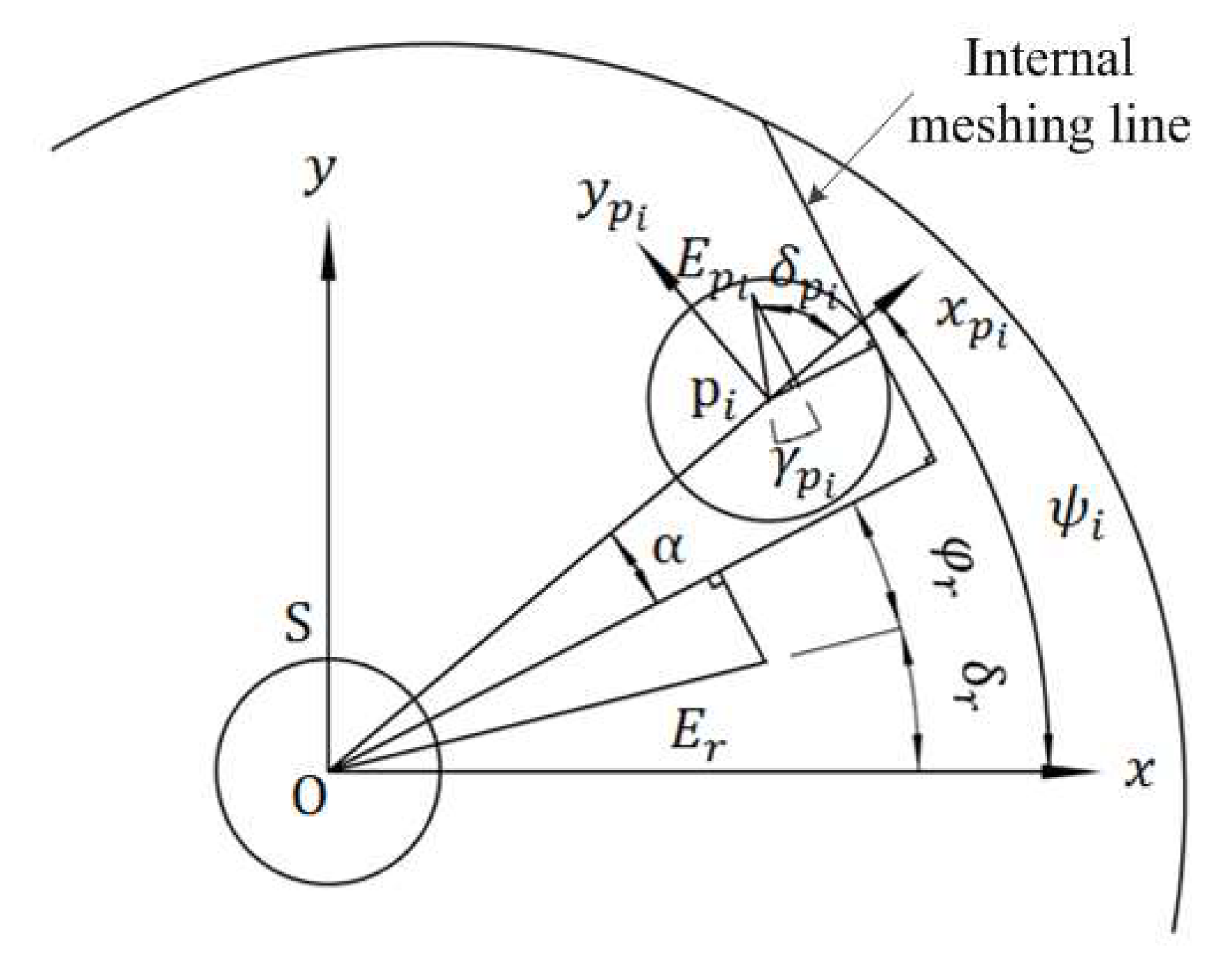
2.3. Modeling of the Transmission Process for the Planetary Gear
2.4. Modeling of the Transmission Process for the Differential Bevel Gear
3. Dynamic Characteristics Analysis and Test of the Transmission Process for DCDS
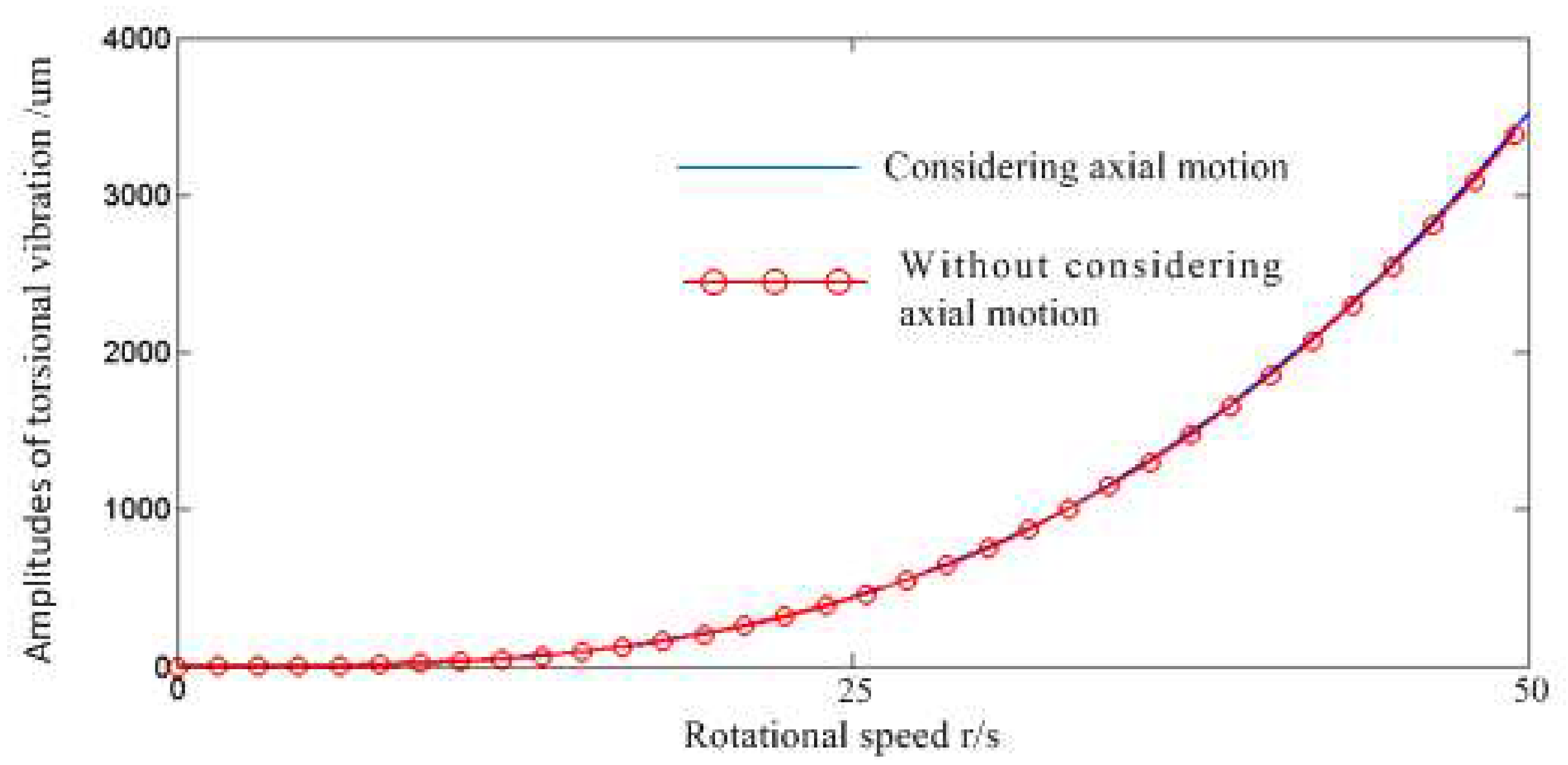
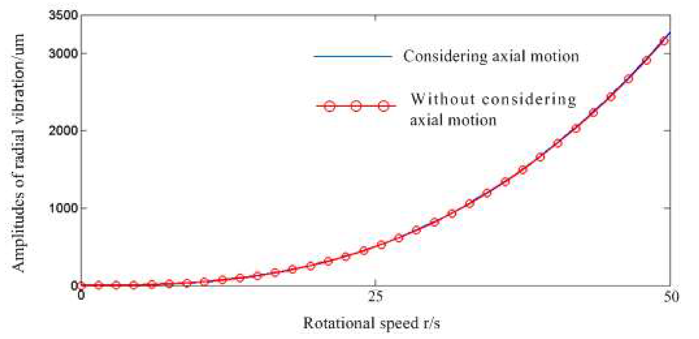
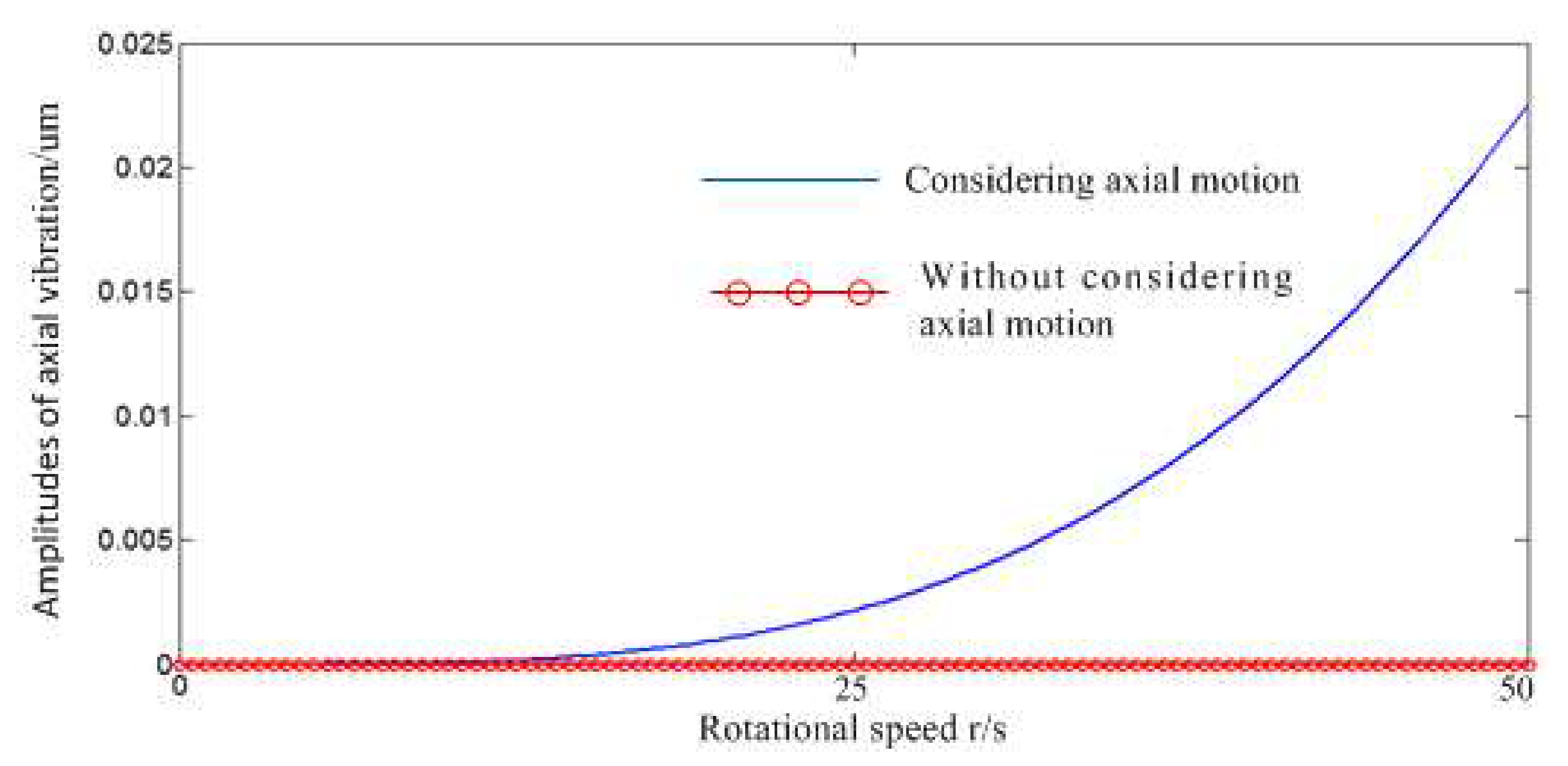
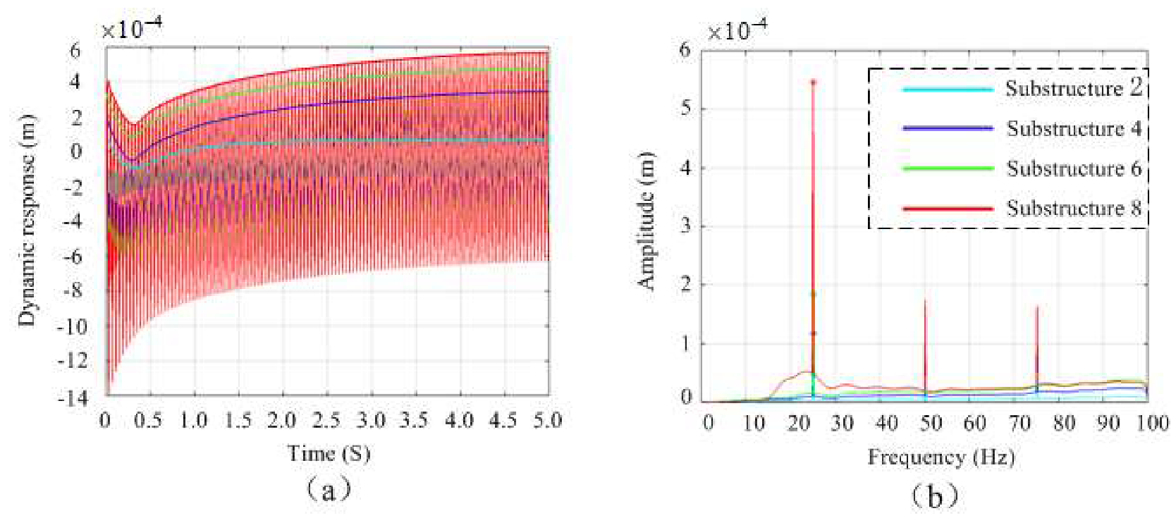
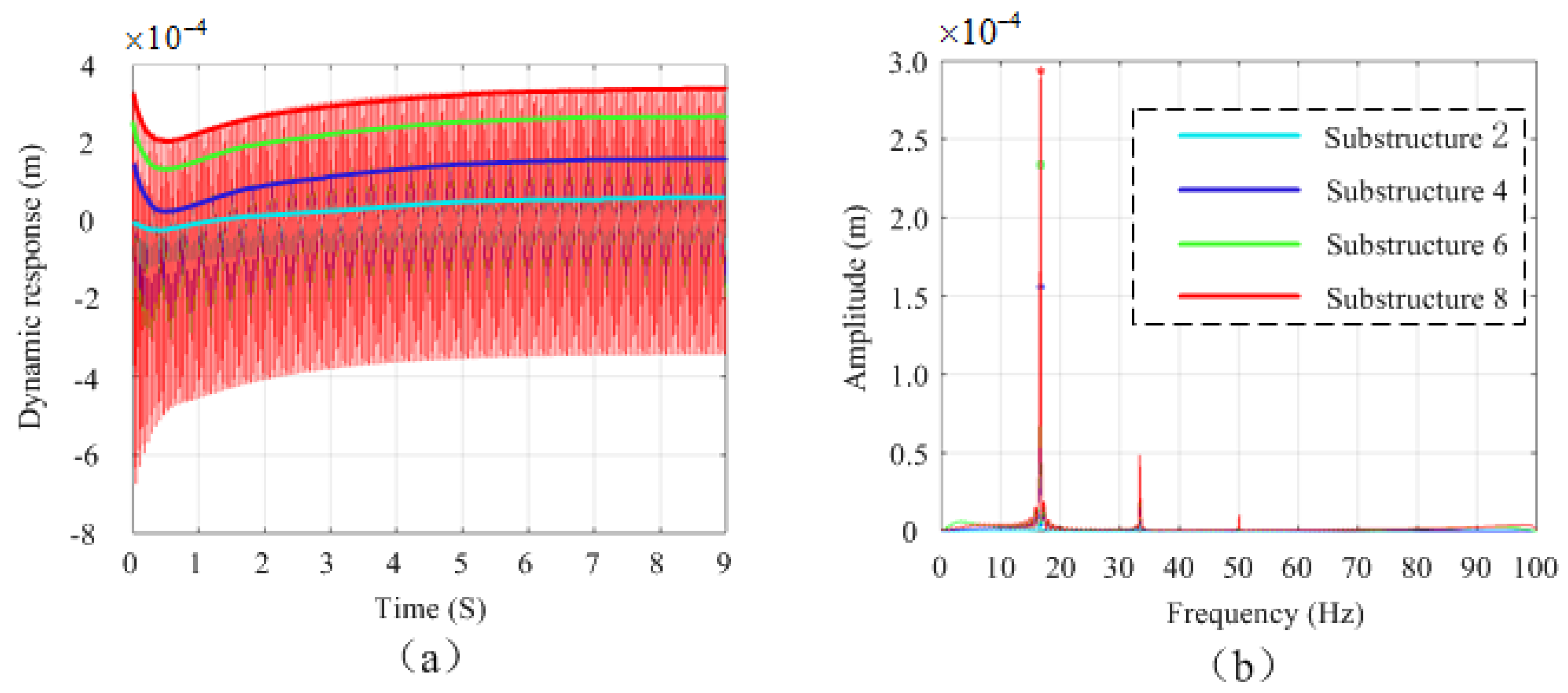
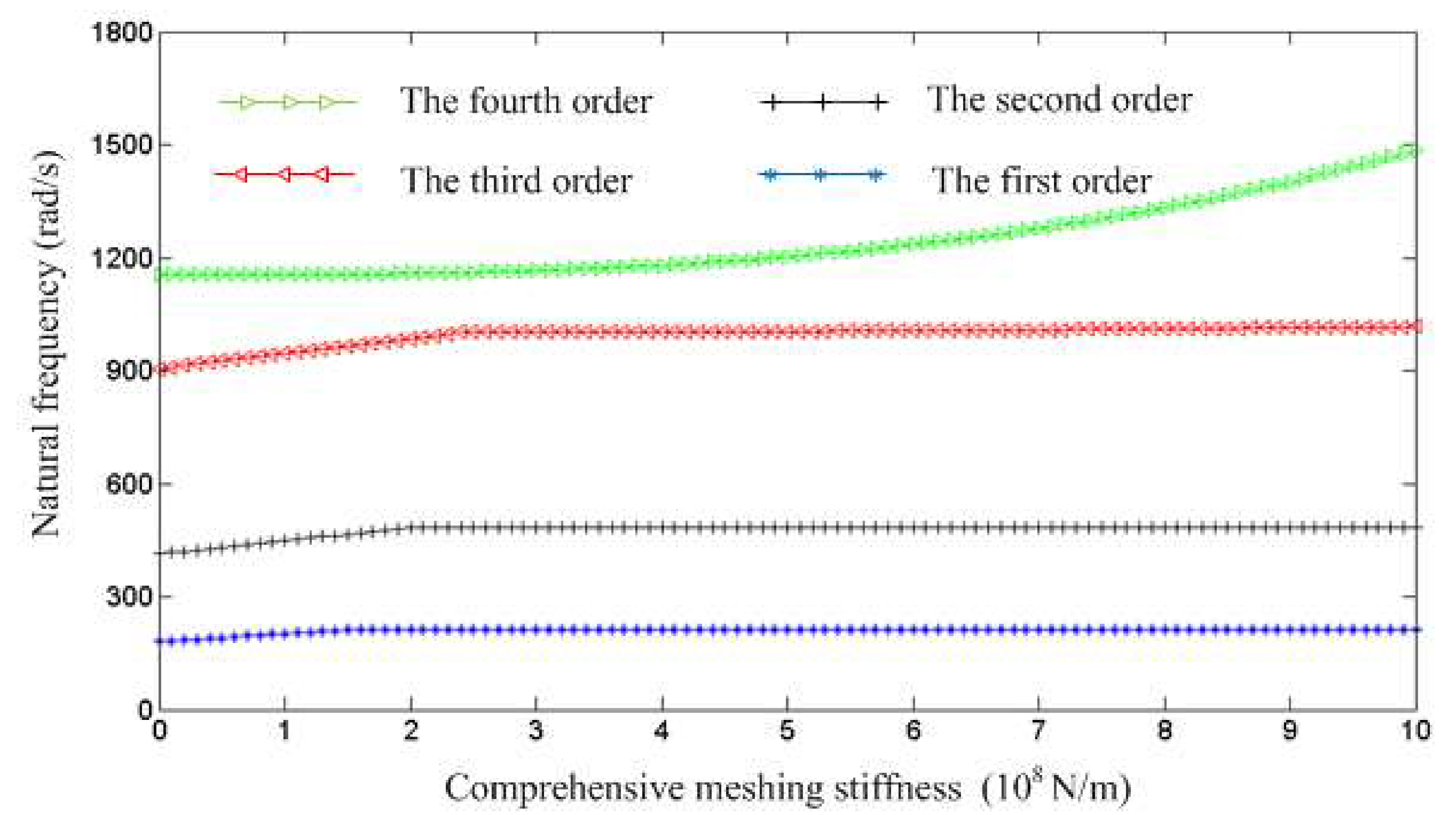
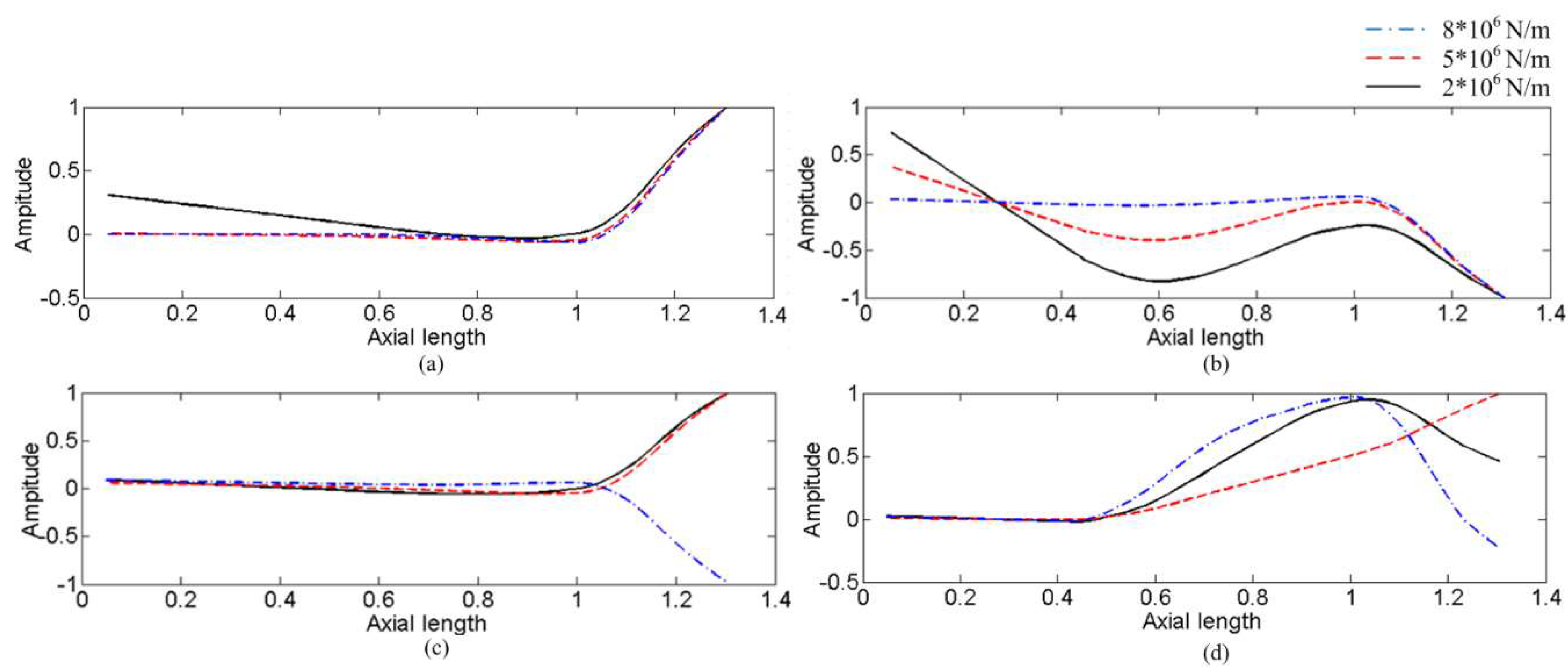
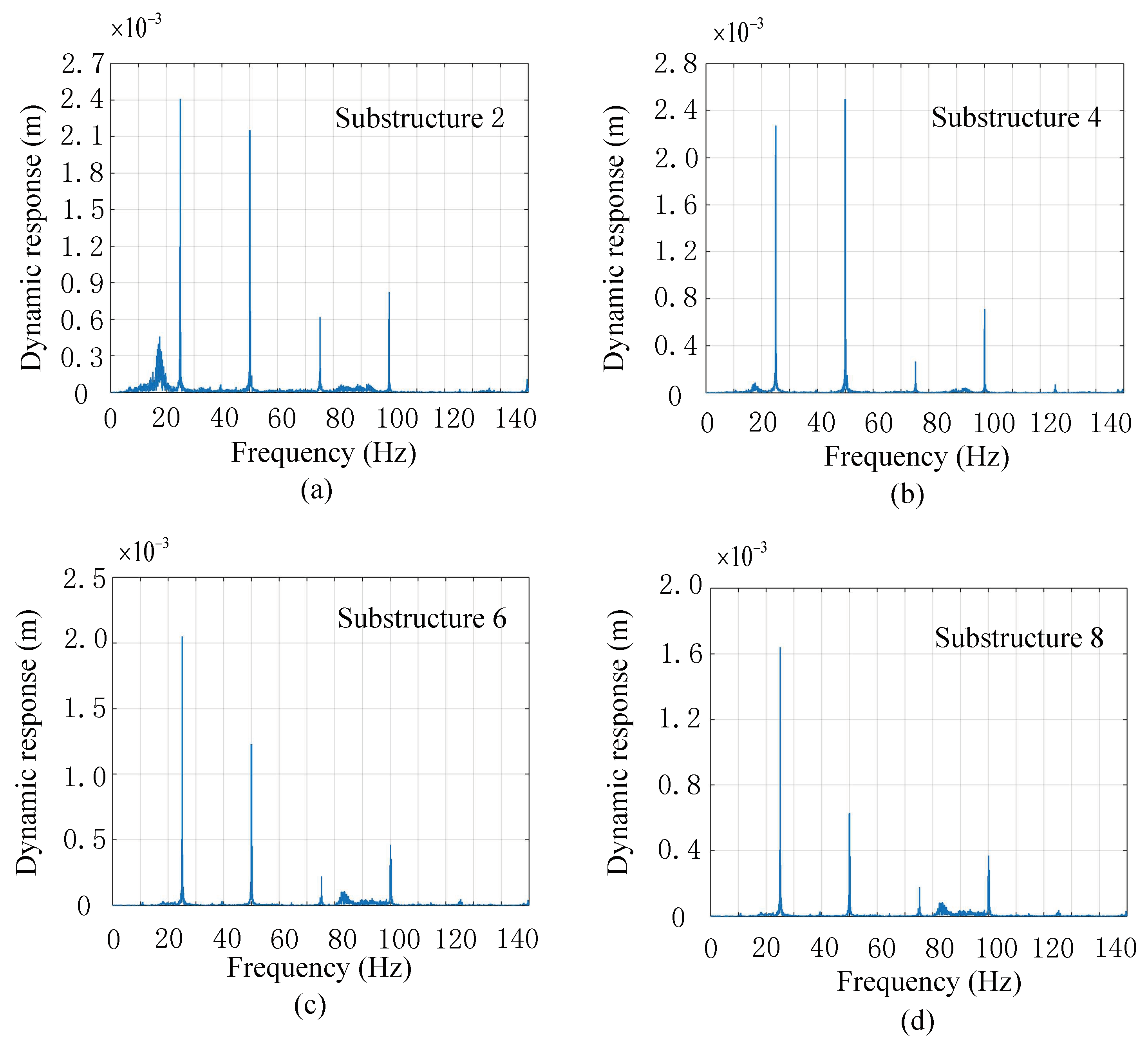
3.1. Dynamic Characteristics Analysis
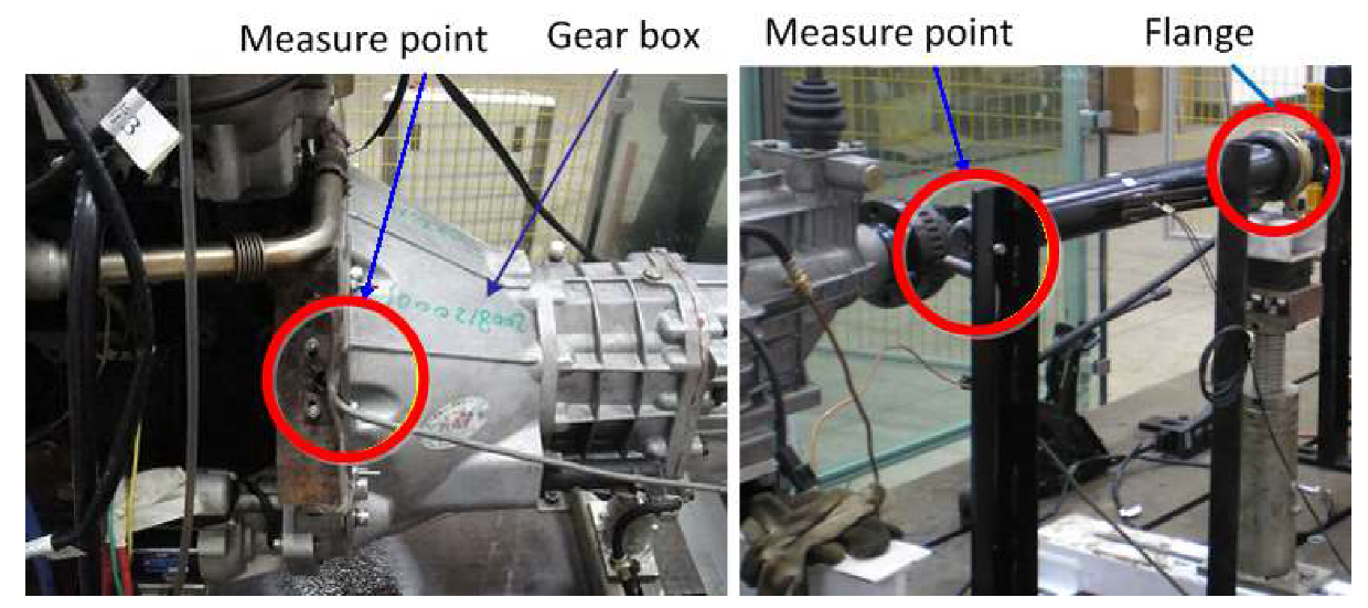
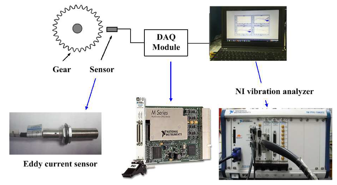
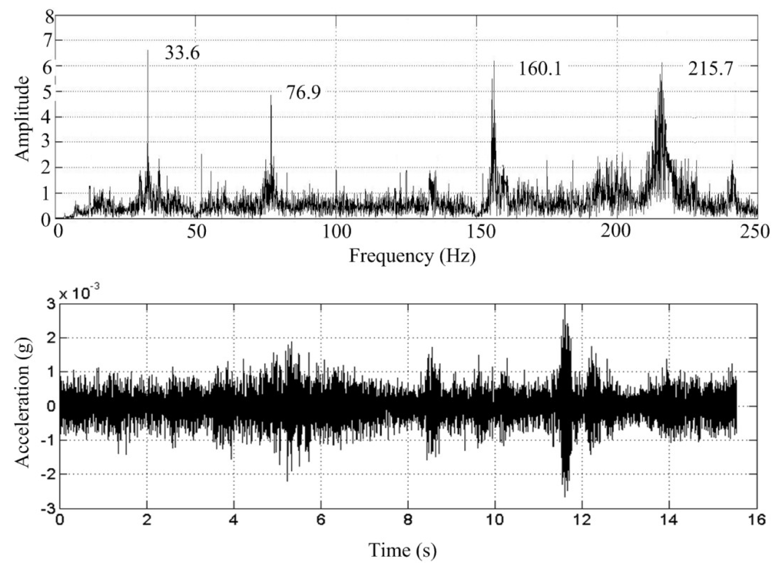
3.2. Experiment Setup and Test
4. Conclusions
Author Contributions
Funding
Conflicts of Interest
References
- Hu, J.; Zheng, L.; Jia, M.; Zhang, Y.; Pang, T. Optimization and Model Validation of Operation Control Strategies for a Novel Dual-Motor Coupling-Propulsion Pure Electric Vehicle. Energies 2018, 11, 754. [Google Scholar] [CrossRef] [Green Version]
- Utkin, V.I. Sliding mode control design principles and applications to electric drives. IEEE Trans. Ind. Electron. 1993, 40, 23–36. [Google Scholar] [CrossRef] [Green Version]
- Klaus, H. High Voltage Electric Vehicle-Implement Interface. SAE Int. J. Commer. Veh. 2008, 1, 383–391. [Google Scholar]
- Fan, W.; Lu, H.; Zhang, X.B. Two-Degree-Of-Freedom Dynamic Model-Based Terminal Sliding Mode Control with Observer for Dual-Driving Feed Stage. Symmetry 2018, 10, 488. [Google Scholar] [CrossRef] [Green Version]
- Wang, H.; Sun, F. Dynamic Modeling and Simulation on a Hybrid Power System for Dual-Motor-Drive Electric Tracked Bulldozer. Appl. Mech. Mater. 2014, 494, 229–233. [Google Scholar] [CrossRef]
- Zhang, S.; Xiong, R.; Zhang, C.; Sun, F. An optimal structure selection and parameter design approach for a dual-motor-driven system used in an electric bus. Energy 2016, 96, 437–448. [Google Scholar] [CrossRef]
- Thompson, A.G. Optimal and Suboptimal Linear Active Suspensions for Road Vehicles. Veh. Syst. Dyn. 1984, 13, 61–72. [Google Scholar] [CrossRef]
- Kim, C.; Ro, P.I.; Kim, H. Effect of the suspension structure on equivalent suspension parameters. Proc. Inst. Mech. Eng. Part D J. Automob. Eng. 1999, 213, 457–470. [Google Scholar] [CrossRef]
- Kim, Y.J.; Song, B.; Kim, J. Load torque estimation for a parallel hybrid agricultural vehicle in field operations. Int. J. Precis. Eng. Manuf. 2013, 14, 1865–1868. [Google Scholar] [CrossRef]
- Chen, L.; Liu, F. Stability analysis of motor-driven actuators in dry clutches with nonlinear stiffness element. In Proceedings of the American Control Conference, Seattle, WA, USA, 24–26 May 2017; IEEE: Seattle, WA, USA, 2017. [Google Scholar]
- Bin, X.; Chao, Z.; Shuo, C.; Enrong, M.; Yuefeng, D. Transmission performance of two-wheel drive electric vehicle. Trans. Chin. Soc. Agric. Mach. 2015, 46, 8–13. [Google Scholar]
- Berriri, M.; Chevrel, P.; Lefebvre, D. Active damping of automotive powertrain oscillations by a partial torque compensator. Control Eng. Pract. 2008, 16, 874–883. [Google Scholar] [CrossRef]
- Wang, S.Y.; Sinha, S.C. Parametric Instability in a Gear Train System Due to Stiffness Variation. In Proceedings of the ASME 2013 International Design Engineering Technical Conferences and Computers and Information in Engineering Conference, Portland, OR, USA, 4–7 August 2013. [Google Scholar]
- Parker, R.G.; Agashe, V.; Vijayakar, S.M. Dynamic Response of a Planetary Gear System Using a Finite Element Contact Mechanics Model. J. Mech. Des. 2000, 122, 304. [Google Scholar] [CrossRef]
- Parker, R.G. A Physical Explanation for the effectiveness of planet phasing to suppress planetary gear vibration. J. Sound Vib. 2000, 236, 561–573. [Google Scholar] [CrossRef] [Green Version]
- Kahraman, A. Load sharing characteristics of planetary transmissions. Mech. Mach. Theory 1994. [Google Scholar] [CrossRef]
- Qiu, X.; Han, Q.; Chu, F. Load-sharing characteristics of planetary gear transmission in horizontal axis wind turbines. Mech. Mach. Theory 2015, 92, 391–406. [Google Scholar] [CrossRef]
- Duchemin, M.; Berlioz, A.; Ferraris, G. Dynamic Behavior and Stability of a Rotor under Base Excitation. J. Vib. Acoust. 2006, 128, 576–585. [Google Scholar] [CrossRef]
- Han, Q.; Chu, F. Dynamic response of cracked rotor-bearing system under time-dependent base movements. J. Sound Vib. 2013, 332, 6847–6870. [Google Scholar] [CrossRef]
- Shen, T.; Dong, Y.; Nuchkrua, T. On Asymptotical Stability Contouring Control of Dual-arm Robot with Holonomic Constraints: Modified Distributed Control Framework. IET Control Theory Appl. 2019, 13, 2877–2885. [Google Scholar]
- Kahraman, A. Natural Modes of Planetary Gear Trains. J. Sound Vib. 1994, 173, 125–130. [Google Scholar] [CrossRef]


| Planetary Gear | Differential Bevel Gear | ||
|---|---|---|---|
| Number of teeth | 20 | Number of teeth | 35 |
| Modulus | 1.5 | Modulus at main aspect | 1.5 |
| Pressure angle | 20 | Pressure angle | 20 |
| Length of shaft | 30 mm | Cone apex angle | 45 |
| Helical angle | 12.5 | ||
| Order | Natural Frequency of Dynamic Model (rad/s) | Natural Frequency of Experimental Test (rad/s) | Relative Error (%) |
|---|---|---|---|
| First | 219.604 | 211.008 | 4.07 |
| Second | 500.219 | 482.932 | 3.58 |
| Third | 1083.379 | 1005.428 | 7.75 |
| Fourth | 1389.928 | 1354.596 | 2.61 |
© 2020 by the authors. Licensee MDPI, Basel, Switzerland. This article is an open access article distributed under the terms and conditions of the Creative Commons Attribution (CC BY) license (http://creativecommons.org/licenses/by/4.0/).
Share and Cite
Fan, W.; Yang, Y.; Su, X. Dynamic Modeling and Vibration Characteristics Analysis of Transmission Process for Dual-Motor Coupling Drive System. Symmetry 2020, 12, 1171. https://doi.org/10.3390/sym12071171
Fan W, Yang Y, Su X. Dynamic Modeling and Vibration Characteristics Analysis of Transmission Process for Dual-Motor Coupling Drive System. Symmetry. 2020; 12(7):1171. https://doi.org/10.3390/sym12071171
Chicago/Turabian StyleFan, Wei, Yongfei Yang, and Xiangang Su. 2020. "Dynamic Modeling and Vibration Characteristics Analysis of Transmission Process for Dual-Motor Coupling Drive System" Symmetry 12, no. 7: 1171. https://doi.org/10.3390/sym12071171