Article

Numerical Simulation of Drag Reduction on a Square Rod Detached with Two Control Rods at Various Gap Spacing via Lattice Boltzmann Method

1
Mathematics Department, SBK Women’s University, Quetta 87300, Pakistan
2
Faculty of Mathematics and Statistics, Ton Duc Thang University, Ho Chi Minh City 72915, Vietnam
3
Mathematics Department, COMSATS University, Islamabad 44000, Pakistan
4
Department of Mathematics, Cankaya University, 06790 Ankara, Turkey
5
Institute of Space Sciences, 077125 Magurele, Romania
6
Department of Medical Research, China Medical University Hospital, China Medical University, Taichung 404, Taiwan
7
Department of Mathematics, College of Arts and Sciences, Wadi Aldawaser, 11991, Prince Sattam bin Abdulaziz University, Al-Kharj 16278, Saudi Arabia
*
Author to whom correspondence should be addressed.
Symmetry 2020, 12(3), 475; https://doi.org/10.3390/sym12030475
Submission received: 16 January 2020 / Revised: 28 February 2020 / Accepted: 5 March 2020 / Published: 18 March 2020

Abstract

:
Numerical simulations are performed to examine the effect of size of control rods (d1) and spacing ratio (g) on flow around a square rod with upstream and downstream control rods aligned in-line using the lattice Boltzmann method (LBM). The Reynolds number (Re) is fixed at Re = 160, while the spacing between the main rod and control rods is taken in the range 1 ≤ g ≤ 5 and the size of the control rod is varied between 4 and 20. Seven different types of flow mods are observed in this study at different values of g and d1. Variation in force statistics, like mean drag coefficient (Cdmean), Strouhal number (St), root mean square values of drag (Cdrms) and lift coefficients (Clrms), and percentage reduction in mean drag coefficient is discussed in detail. It was examined that vortex shedding completely suppressed at (g, d1) = (1, 12), (2, 12), and (2, 16) where steady flow mode exists. Moreover, it was found that at large gap spacing, where g = 5, the effect of control rods on the main rod vanishes. Due to this strong vortex shedding produced and as a result, maximum value of Cdmean is found at (g, d1) = (5, 8). The negative values of mean drag force are also observed at some gap spacing and size of control rods are due to the effect of thrust. Furthermore, the maximum percentage reduction in Cdmean is 121%, found at (g, d1) = (2, 20).

1. Introduction

When a structure is exposed to fluid flow, it experiences fluid forces like drag and lift. These forces may cause vibrations of the structure and at favorable conditions can trigger the structure. In the present study an attempt is made to reduce these forces. The shed vortices of a square rod are suppressed by placing two control rods in an upstream and downstream position aligned in-line with the main rod. This type of flow control method is classified as passive control method. The other method that requires external energy in order to control fluid flow is known as active control method. The implementation of passive method is easy as compared to active method. Control plate and small secondary control rods are the two most important passive control devices widely used in literature for the suppression of vortex shedding and reduction of fluid forces. Many studies available in literature are based on passive control method to control flow and save energy.
Mittal and Raghuvanshi [1] examined the vortex suppression behind the main circular rod with two small control rods and found the vortex shedding suppression at low range of Reynolds number (Re) under suitable location of the main and control rod. Zhao et al. [2] numerically investigated that the mean drag coefficient (Cdmean) and root-mean-square value of lift coefficient (Clrms) depend strongly on the gap between the main and small control rods. Turki [3] examined the influence of a control plate’s length on vortex shedding behind a square rod numerically and observed that for Re < 150, the Strouhal number (St) started to decrease and for Re ≥ 150, the St increased by increments in length of the plate. The jump in mean drag coefficient (Cdmean) at Re = 150 and 200 was also examined. Kuo and Chen [4] employed the passive control method to overcome fluid forces on a circular rod in the uniform flow by putting two control rods symmetrically at various stream locations of the main circular rod. They investigated that at 0.8 ≤ g ≤ 3, the Clrms values on the main rod showed a 70%–80% reduction. Malekzadeh and Sohankar [5] studied the reduction of fluid forces on a square rod through passive control method by placing a control plate at the upstream position. This study was carried out at Re = 50–200, the width of control plate was taken between 0.1 and 0.9, and gap spacing varied between 0.1 to 0.7. They reported maximum reduction of fluid forces, when the width of the control plate was 0.5 and g = 3. Ali et al. [6] numerically studied the wake alteration behind a square rod attached with downstream control plate at Re = 150. They examined the sensitivity in the near wake structure for changing the spacing ratio. They observed the flow mode within the gap and downstream of the channel. Moreover, a sudden jump in St values was also observed at g = 2–2.5. Wu et al. [7] experimentally studied the suppression in vortex shedding using multiple control rods. They used four small circular rods of the same size attached to the main circular rod at 2400 < Re < 7600. Bao and Tao [8] examined the fluid force reduction on a circular rod using dual control plates arranged parallel to each other numerically. They reported that the delay of vortex shedding over the main rod with two control plates is more when compared to a single control plate. They also observed stronger wake suppression at relatively shorter control rod lengths. Gupta [9] analyzed the reduction of vortex induced vibration behind a square rod in the presence of a small control rod by using Re = 100 and reported 10% to 15% in drag reduction. Two-dimensional lattice Boltzmann was used by Islam et al. [10] at Re = 100 and 160 for flow behind a square rod detached with multiple control rods. They reported maximum drag reduction at g = 3 and also reported the effect of thrust. Lu et al. [11] examined the effect of multiple control rods, g, and Re on the flow modes and on fluid dynamic forces of a circular rod through the finite element method. Vamsee et al. [12] performed numerical simulations to investigate the effect of a single upstream control plate and two control plates in the upstream and downstream position of a single square rod. They examined that the length of the control plate and its position play an important role in controlling the flow behind the main rod. Islam et al. [13] numerically studied different flow regimes for flow over a square rod with a downstream control plate at Re = 150 and g = 0–11. They classified the flow into extended-body (0 ≤ g ≤ 1.53), reattachment (1.9 ≤ g ≤ 4), and fully developed (4.8 ≤ g ≤ 11) flow regimes. The authors reported that g = 2 is the optimum space and the maximum reduction in drag force was examined at g = 0. Islam et al. [14] examined the influence of Reynolds number on flow over a square rod using passive control method for small, moderate, and wide gap spacings. They found maximum reduction in force coefficients at closely gapped spacing and observed fully developed flow at moderate and wide gap spacings. Islam et al. [15] observed a reduction in Cdmean of 8.3%, when two control rods were placed at an upstream distance, 51% when the two control rods were placed at a downstream distance and 50.8% when four control rods were placed upstream and downstream of a square rod. Islam et al. [16] placed three control rods upstream and three downstream of a main rod and studied the effect of Re and g. They found weakly vortex shedding, and steady and strongly-induced vortex shedding flow modes. They examined that the vortex shedding suppression was dependent on both g and Re, but the latter one was more effective.
From the above discussion it was observed that investigations related to the effect of controlling devices on the reduction of fluid forces and vanishing of vortex shedding behind a square rod are still far from complete. Due to this fact, the present study was conducted in order to investigate the effect of gap spacing and size of control rods in terms of reduction of fluid forces and to control flow for saving energy. The flow around the chimneys, parallel suspension bridges, the vibrations of radar masts, heat exchanger pipes, and high structures are applications of flow control in industry. It needs to be emphasized that the wake structure mechanism for different flow patterns of flow over a square rod in the presence of small controlling square rods is quite different from that over a circular rod, because in case of a square rod, the separation point is fixed as compared to a circular rod, causing differences in the critical flow patterns. Furthermore, the aerodynamic forces differ significantly and depend on the separation mechanism for two geometries.
Therefore, in the present study five important points will be focused on: (i) Change in flow modes by changing d1 and g; (ii) influence of g and d1 on flow mechanism; (iii) existence of optimum spacing and size of control rod; and (iv) to find ideal gap spacing and size of control rod in terms of maximum reduction. These points will be analyzed in terms of vorticity, time-signal analysis of fluid forces, and variation in force statistic.

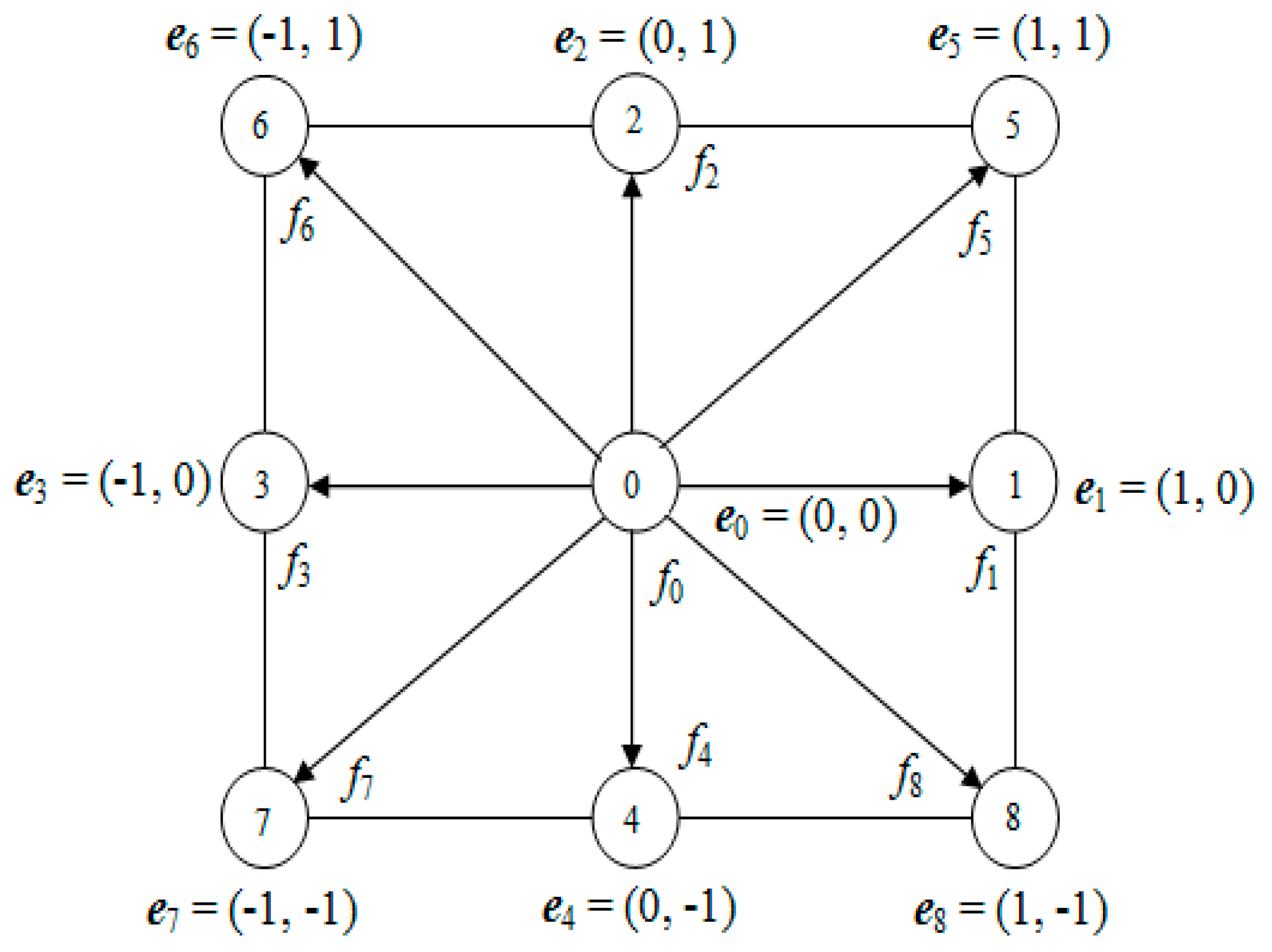
2. Lattice Boltzmann Method

The numerical technique lattice Boltzmann method (LBM) is an effective approach used to solve complex fluid problems, either those single or multiphase flows, and will be used here to solve this problem [17,18]. This numerical technique has several merits as compared to other techniques, such as the finite volume or finite element methods. For example, the streaming and collisions are local in nature, which provide an opportunity for parallel computing [18]. It is explicit in nature and the non-linear term in the Navier-Stokes equation [18] can easily be handled through this method. It is second-order accurate in both space and time [19,20]. In this technique, the pressure is calculated through the equation of state. The model used here is the two-dimensional nine particles (D2Q9) velocity model (Figure 1). The general form of the Boltzmann transport equation is:
f i ( x + e i ,   t   + 1 ) =   f i ( x ,   t ) 1 τ [ f i ( x ,   t )   f i eq ( x ,   t ) ] ;
where f i ( x ,   t ) and f i eq ( x ,   t ) are distribution and equilibrium distribution functions and τ is the stability parameter. The equilibrium distribution function is defined as:
f i eq ( x ,   t ) =   w i ρ [ 1 + 3 ( e i . u ) / c 2 + 4.5 ( e i . u ) 2 / c 4 1.5 u 2 / c 2 ]
Numerically, Equation (1) is solved in two steps:
Streaming:
f i ( in ) ( x ,   t ) = f i ( out ) ( x     e ,   t     1 ) ,
Collision:
f i ( out ) ( x ,   t ) =   f i ( in ) ( x ,   t )   1 τ [ f i ( in ) ( x ,   t )   f i eq ( x ,   t ) ]
The density ρ and momentum ρ v of particles are calculated as:
ρ = i = 0 8 f i ,   ρ v = i = 1 8 f i e i
The weighting coefficients ( w i ) for D2Q9 model are
w 0 = 4 / 9 ,
w 1 =   w 2 =   w 3 =   w 4 = 1 / 9
w 5 =   w 6 =   w 7 =   w 8 = 1 / 9 ,
The kinematics viscosity is defined as [18]:
ν = 1 / 3 ( τ 0.5 ) ,

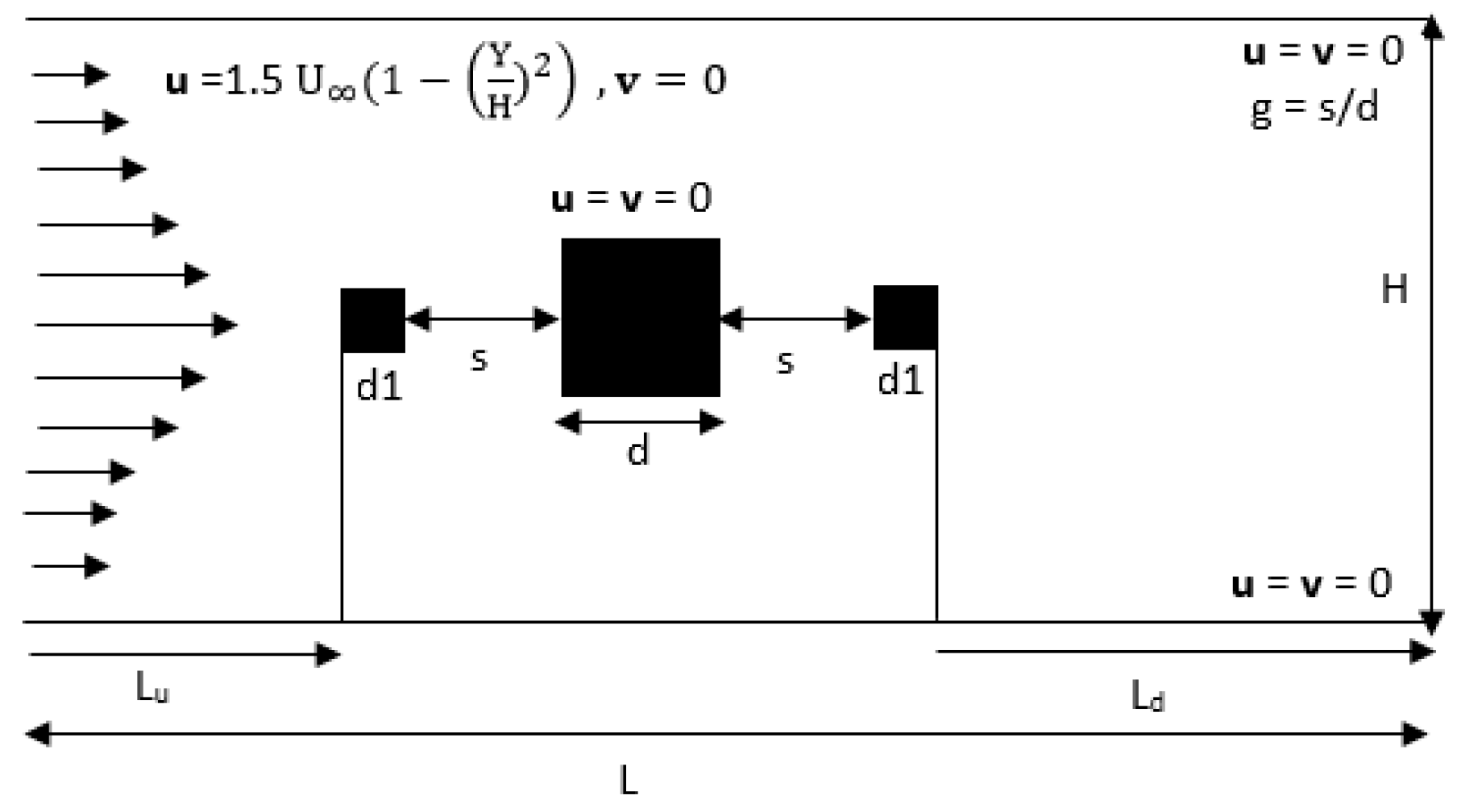
3. Problem Statement, Boundary Conditions, and Important Parameters

The schematic diagram for flow over a square rod of size ‘d’ detached with two small control rods of size ‘d1’ in upstream and downstream position is presented in Figure 2. The gap (g) between the main rod and control rods is similar. The effect of spacing and size of control rods on the overall fluid force reduction and vortex shedding suppression is analyzed for spacing to main rod size ratio g = s/d = 1–5 and size of rod d1 = 4–20 at fixed Re = 160. The upstream and downstream distances and height of the channel are fixed in this study at Lu = 8d, Ld = 33d, and H = 11d, respectively. L is the length of the channel in the horizontal direction and it varies by changing the spacing values within the main rod and control rods.
The parabolic velocity profile ( u = 1.5   U ( 1 ( y H ) 2 ) ,   v = 0 ) is incorporated at the inlet of the channel [21]. The no-slip boundary condition (bounce back treatment) is used for flow at the surface of control rods and main square rod as well on the upper and lower walls of the channel [21]. The convective type boundary condition ( u t + U u x = 0 ) is assigned at the exit of the channel [22]. The momentum exchange method is employed to calculate the total fluid forces [20]. Some essential physical parameters used in the present work are defined as follows:
The Reynolds number is defined as:
Re   = U max d ν
The Strouhal number (St), drag coefficient (Cd), lift coefficient (Cl), root-mean-square value of drag (Cdrms), and lift coefficients (Clrms) are given as:
St   = f s d U
C d = F d 0.5 ρ U 2 d
C l = F d 0.5 ρ U 2 d
C drms = t = 1 n [ Cd ( t ) mean ( Cd ) ] 2 / n
C lrms = t = 1 n [ Cl ( t ) mean ( Cl ) ] 2 / n
where fs is the vortex shedding frequency, Fd and Fl are the components of force in longitudinal and transverse direction, respectively, and n is the total number of time steps.

4. Code Validity and Grid Independence Study

To check the accurate grid points, 10, 20, and 40 grid points were selected and calculated the values of Cdmean, Cdrms, and Clrms against the chosen grid points. These calculated values were compared with one another at Re = 160 and presented in Table 1. The upstream distance Lu is 8 d and downstream distance Ld is 33 d. It is clear from the results represented in the table that the 20-point grid gives accurate results to fulfill the convergence criteria as compared to other selected grid points. Guo et al. [21] also found the accuracy of a 20-point grid to meet the convergence criteria.
For validation of the code, the calculated values of force statistics like Cdmean, Cdrms, and Clrms for flow over a square rod at Re = 100 and 150 for this study were compared with the experimental values of Okajima [23], Norberg [24], and numerical values of Sohankar [25], Rubichuax et al. [26], and Abograis and Alshayji [27] for flow past a single rod (see Table 2). It can be seen that the present result shows similar values with other available studies and negligible differences is found between these values. This indicates that the flow characteristics can be simulated in an effective manner through the present code. The selected cases for the present simulation are given in Table 3.

5. Results and Discussion

5.1. Analysis of Flow Modes

A numerical study was conducted in a two-dimension channel to analyze the reduction in flow induced forces and suppression of vortex shedding behind a main square rod in existence of two square control rods placed at both upstream and downstream locations of the main rod. Computations are carried out by applying LBM at various gap spacings at a fixed Reynolds number of 160. In this section, the analysis of flow mode was presented in terms of vorticity contours and time history analysis of drag and lift coefficients. Seven types of flow modes were examined at different values of gap spacing and size of control rods. The modes are named according to their flow characteristics. In the vorticity graphs the dashed lines represent negative vortices emerging from the upper corner of the rods, while the solid lines represent the positive vortices generated from the lower corner.

5.1.1. Single Bluff Body (SBB) Flow Mode

The first flow mode was observed at a small gap spacing that was g = 1 to 2, while the size of the control rod was d1 = 4 (see Figure 3a,b). Due to the small space, no flow passed between the gaps and the shear layers transformed from the upstream control rod rolled up to form vortices in the region of the downstream control rod only (Figure 3a,b). The triad of rods behave like an isolated body in the flow field and this flow mode is named as single bluff body flow mode. The shed vortices move in an alternate manner towards the downstream location of the channel. It is clear from Figure 3a,b that shed vortices remain distinct throughout the channel after detaching from the main rod and two small control rods. When g is increased from g = 1 to 2, the strength of the generated vortices decreases while the length of shear layer increases. This flow mode was also examined by Zdravkovich [28] at gap spacing within the range g = 1–1.8 and Malekzadeh and Sohankar [5] at h/w = 0.1 (where h is length and w is width of the control plate) for g = 1.1–5 at Re = 160.
Temporal histories of Cd and Cl are presented in Figure 4a–d for SBB flow mode. Lift coefficient shows regular behavior at g = 1 and 2 for d1 = 4 due to an alternate formation of vortices, while drag shows modulated behavior due to change in size and strength of vortices at downstream wake region. The fluctuating magnitude of Cd and Cl coefficients decreases with increasing gap spacing from g = 1–2.

5.1.2. Without Rolled up Shear Layer Reattachment (WSLR) Flow Mode

The second flow mode was observed at (g, d1) = (1, 8), (1, 16), (1, 20), (2, 8), and (2, 20). Here we only discuss the cases (g, d1) = (1, 8), (1, 16), and (2, 20) (see Figure 4a,b). As the gap spacing and size of both the control rods are changed, the flow behaves very differently, and it is no longer SBB flow mode. The shear layer emerges from upstream and the control rod reattaches to the main rod and control rod directly at downstream location without rolling up in the gap between the main rod and downstream control rod. The length of the shear layer at the downstream wake region decreases as g and d1 increase (see Figure 4a,b). It is clear from the vorticity plots of WSLR flow mode that the shear layer detaching from the upstream control rod moves without roll up in the gaps and vortices formed at downstream position of the computational domain (see Figure 4a,b). When the size of the control rods is equal to the size of the main rod then the three in-line square rods shed scattered vortices (Figure 4c).
Temporal variations of Cd and Cl for WSLR flow mode is presented in Figure 4c–f). From the figure it is clear that lift coefficient shows the periodic behavior for both selected cases due to an alternate shed vortice and drag coefficient exhibits modulated behavior due to change in the shape and size of shed vortices. The magnitude of drag force for both cases is negative due to the effect of thrust.

5.1.3. Rolled up Shear Layer Reattachment (RSLR) Flow Mode

The third existing flow mode is called rolled up shear layer reattachment (RSLR) flow mode, that was investigated at (g, d1) = (3, 4), (4, 16), and (5, 4) (see Figure 5a–c). It was noticed that when the gap increased from g = 2 to 5 for different sizes of control rods, then fluid entered in both gaps. The generated shear layer from the upstream control rod rolled up completely but the complete formation of vortices between the gaps does not exist (Figure 5a–c). It can be seen from Figure 5a–c that the shed vortices are observed only at the downstream location of the channel and the strength of shed vortices for small size of control rods (i.e., d1 = 4 is maximum as compared to d1 = 16 for g = 4). This flow mode is also observed at (g, d1) = (3, 12), (3, 16), (3, 20), (4, 4), and (4, 20). Igarashi and Suzuki [29] also investigated this flow behavior and named this mode as with reattachment and roll up flow for three circular rods. This kind of flow mode was also found by Islam et al. [13] for flow past a square rod with a detached control plate.
In Figure 5d–g the time signal analysis of Cd and Cl for RSLR flow mode was presented at (g, d1) = (4, 16) and (5, 4). It can be seen from the figure that for both cases the drag and lift coefficient show periodic behavior. The amplitude of drag force increases with increments in gap spacing from g = 4 to 5 and by decreasing the size of the control rod from d1 = 16 to 4. Yet this trend reverses in case of lift coefficient; this is because as the size of control rods decreases, the strength of vortices increases, which enhances the magnitude of the drag coefficient.

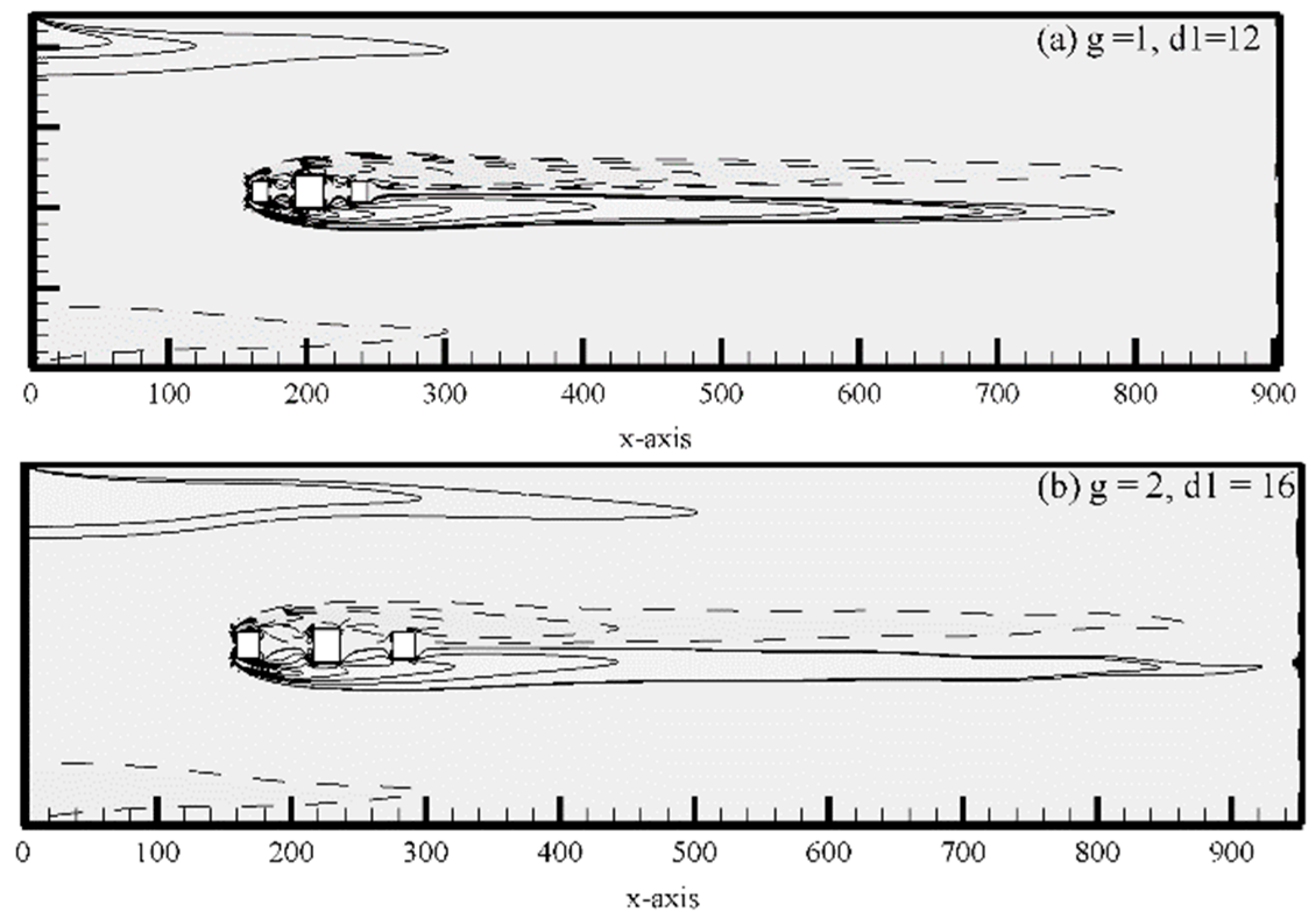
5.1.4. Steady Flow (SF) Mode

The fourth flow mode was observed at (g, d1) = (1, 12), (2, 12), and (2, 16). The vorticity contours of steady flow mode are shown in Figure 6a,b. From Figure 6a,b it is clear that the shear layer emerging from the upstream control rod did not reattach to the main rod as well as the downstream control rod and moved in a similar manner throughout the computational domain. As a result, steady flow behavior was observed and there was no vortex formation. On the basis of these facts, this flow mode is named as steady flow. Due to steady flow the drag and lift coefficient graphs are a straight line (not shown). The straight line for drag coefficient is evidence that there was no formation of vortices. Vamsee et al. [12] found SF behavior for the case of detached dual plates by considering the fixed length of upstream control plate at 1d.

5.1.5. Critical Flow (CF) Mode

The fifth flow mode was named as critical flow mode observed at (g, d1) = (5, 12) and (5, 16). The vorticity contours and corresponding time-trace analysis of drag and lift coefficients are shown in Figure 7a–c; g is large enough to pass the flow. Therefore, fluid enters the gaps between the control rods and main rod and the shed vortices can be seen in the gaps (see Figure 7a,b). The distortion and merging of vortices can be seen at the near wake region of the downstream control rod (Figure 7a,b). This is due to the fact that the unsteady wake emerged causing the upstream control rod to interact with the main rod, which generated a more unstable wake. A similar phenomenon is observed within the main and downstream control rod. In this flow mode the shape and size of shed vortices are different from other flow modes and the shed vortices do not move in a smooth way. Complex amalgamations and detachments in flow are observed downstream of the computational domain. Sewatkar et al. [30] reported critical flow mode for six in-line square rods.
The drag coefficient of critical flow showed more modulation in amplitude of cycles; that is, the amplitude of each cycle varied and after four cycles the amplitude repeated (Figure 7c). This indicates that the amplitude of drag force applied on the main rod is no longer regular. The lift coefficient of this flow mode shows periodic behavior with varying amplitude (see Figure 7d).

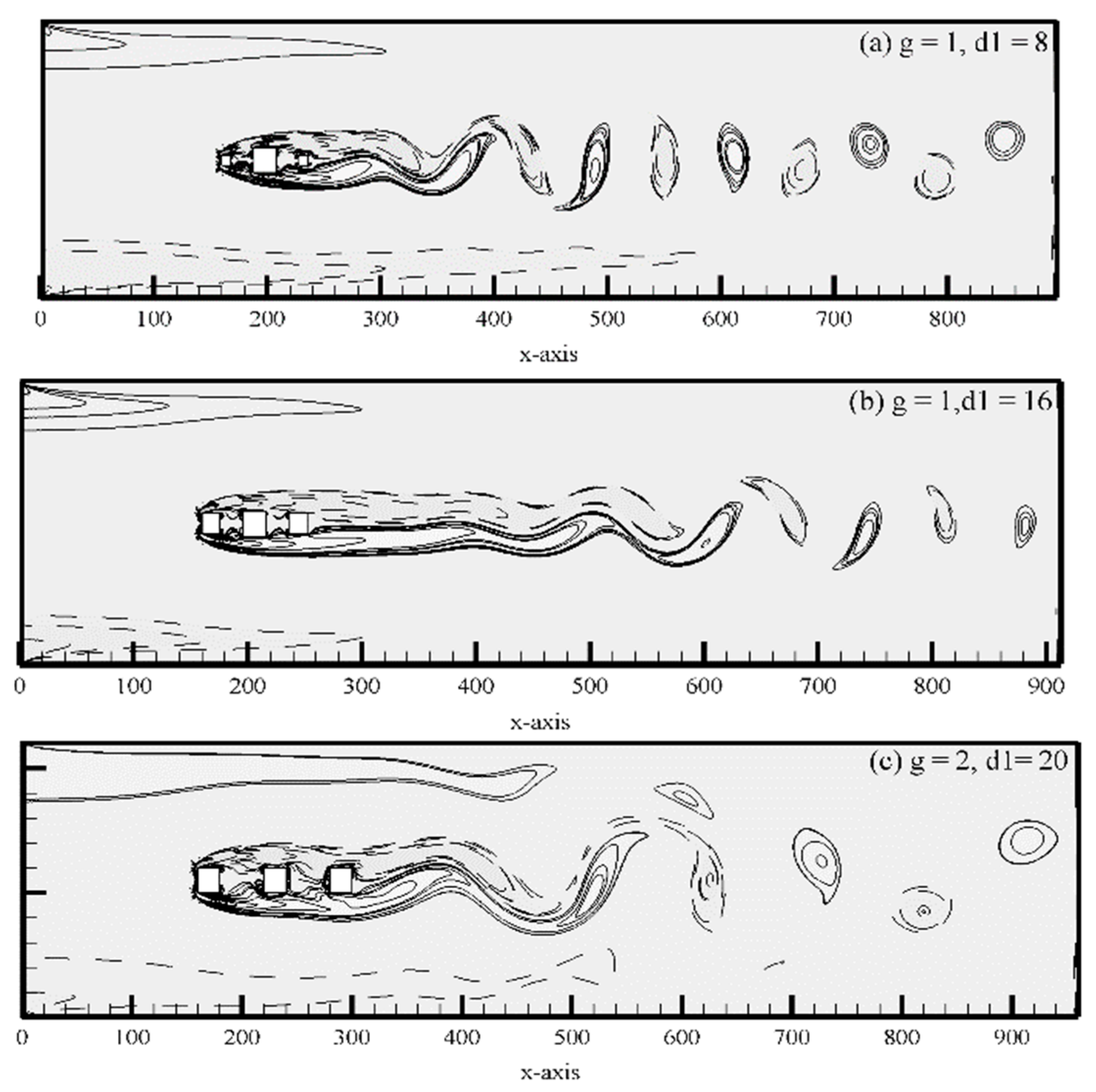
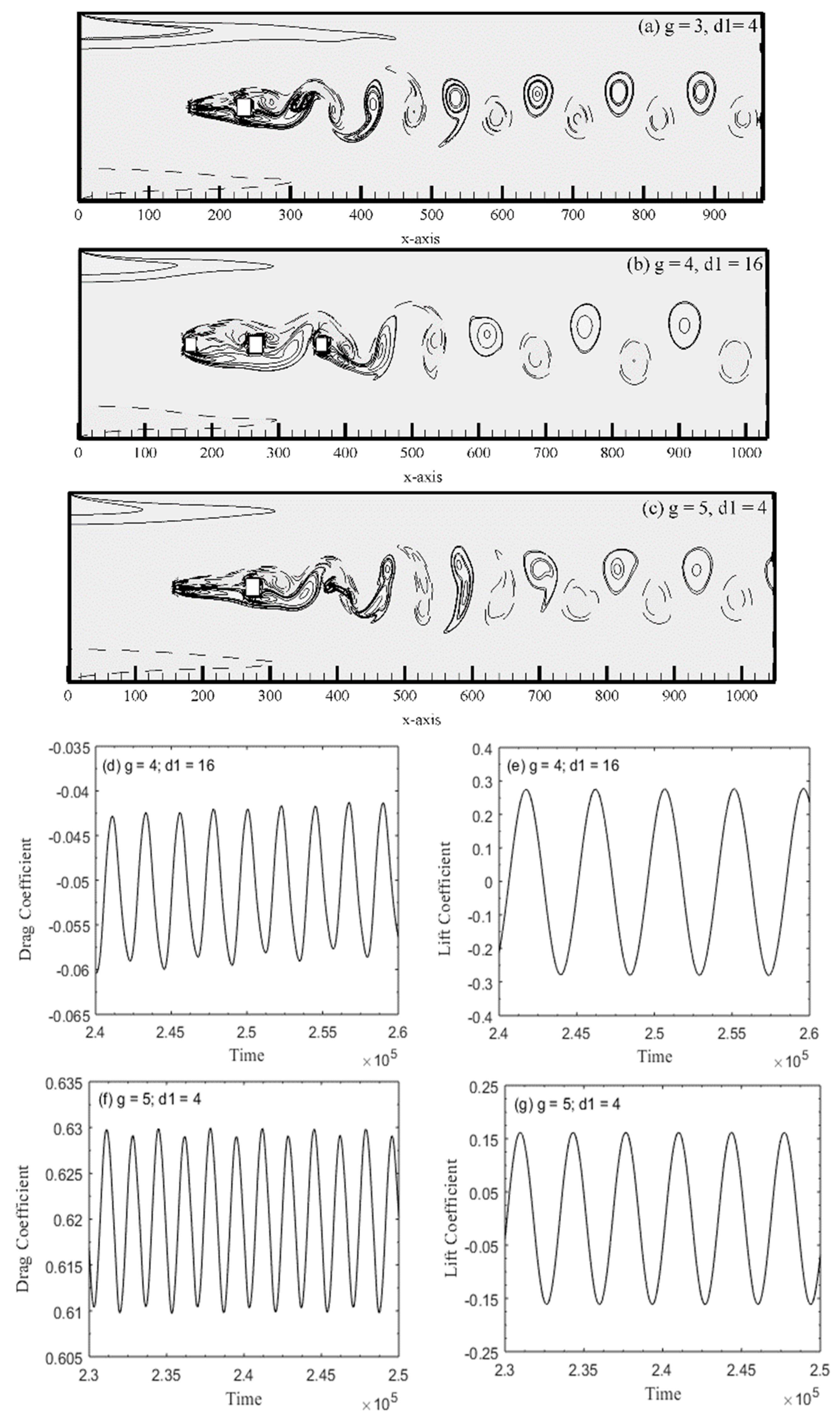
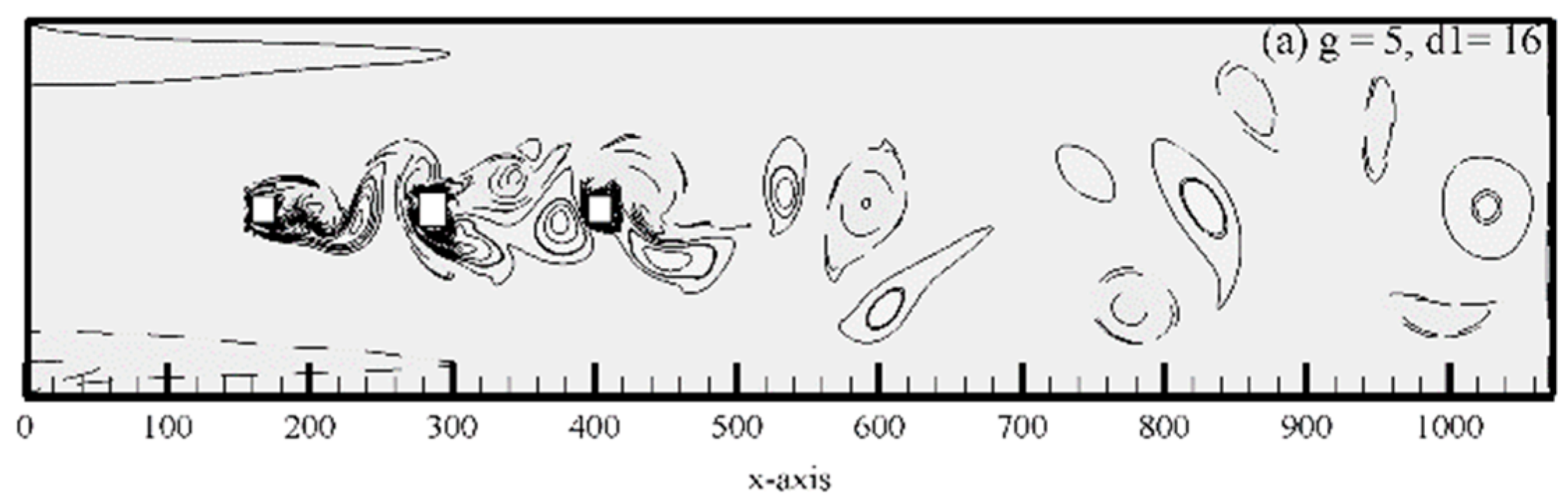
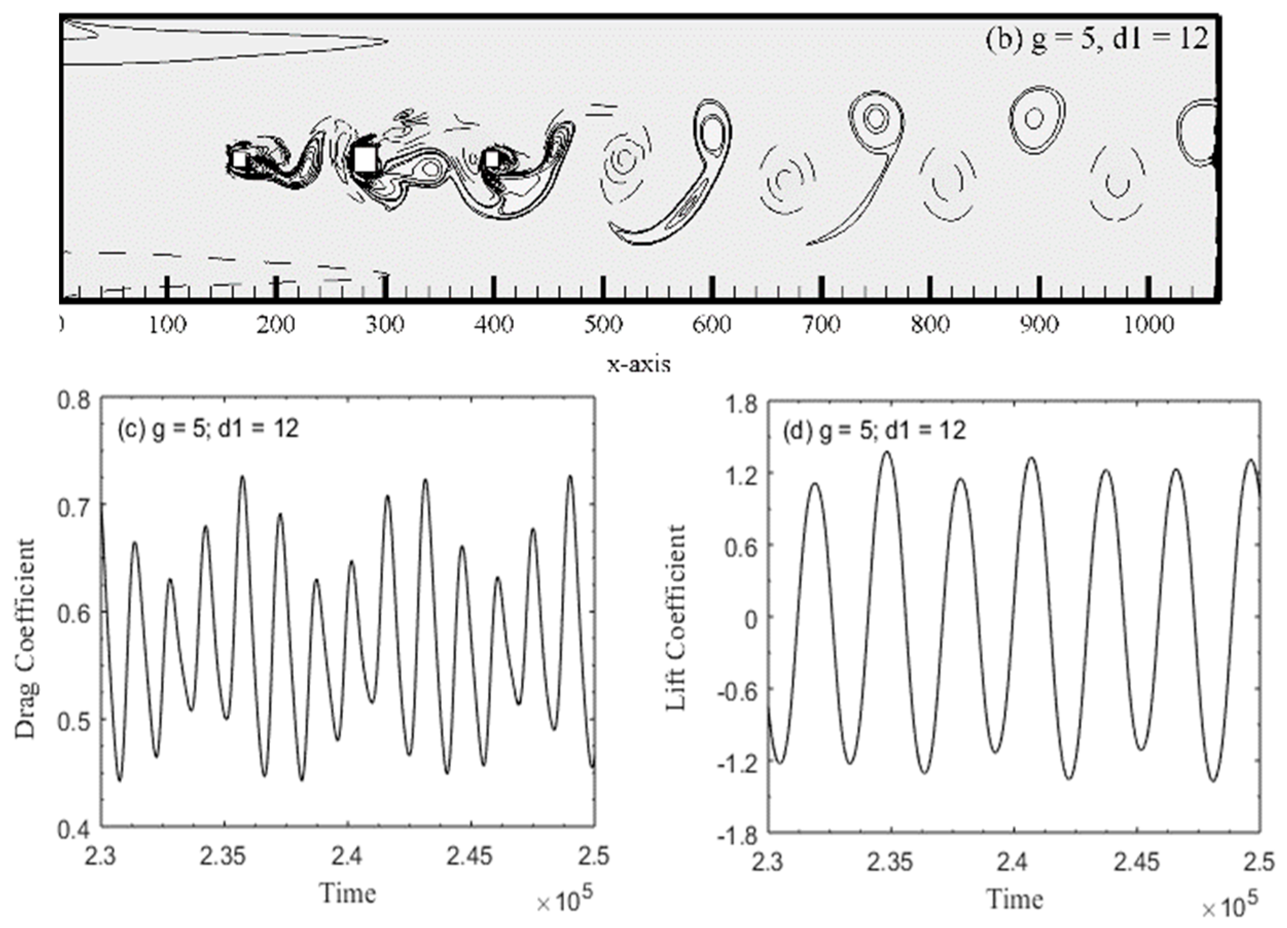
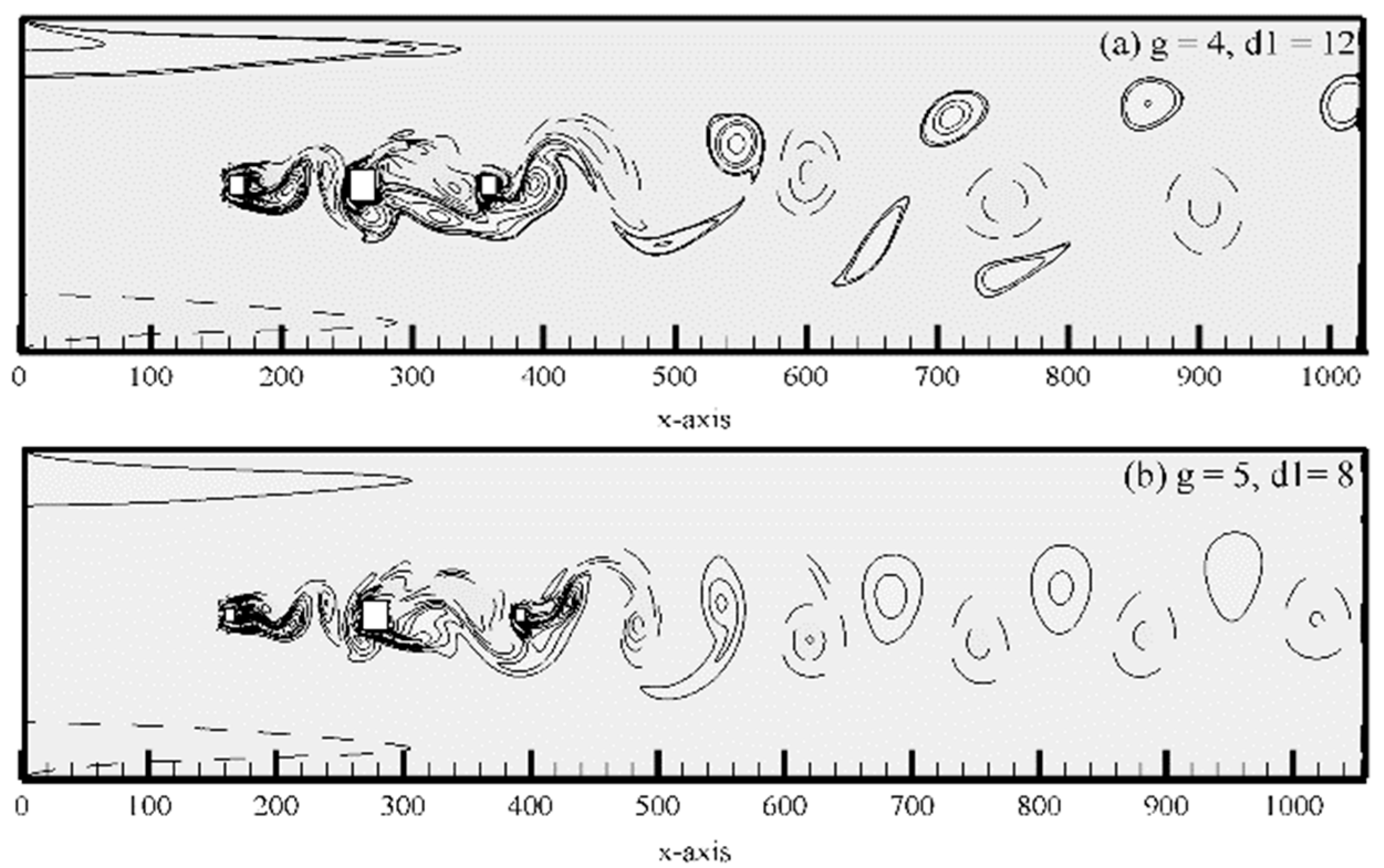
5.1.6. Fully Developed Vortex Street (FDVS) Flow Mode

The next flow mode is named as fully developed vortex street FDVS flow mode observed at (g, d1) = (3, 8), (4, 8), (5, 8) and (4, 12). Here the presented cases are (g, d1) = (4, 12) and (5, 8) for sake of simplicity. In both cases, vortices are seemed to be fully developed within the gap of main rod and control rods as well in downstream location of channel, respectively. At (g, d1) = (4 12), the strength of shed vortices is weak as compared to (g, d1) = (4 12) and size of generated vortices is large enough. Zdravkovich [31] also observed fully developed or co-shedding flow regime at g > 3.8, experimentally at higher range of Re for case of tandem circular rods. Ali et al. [6], also numerically found fully developed flow mode for flow over a square rod with a detached control plate.
Time signal analysis of Cd and Cl for FDVS is presented in Figure 8c–f. Drag and lift coefficients are not periodic and having modulated behavior due to different strength and size of shed vortices. The magnitude of drag coefficient in both selected cases increases with g, but magnitude of lift coefficient decreases with increment in gap spacing for FDVS flow mode (see Figure 8c–f).

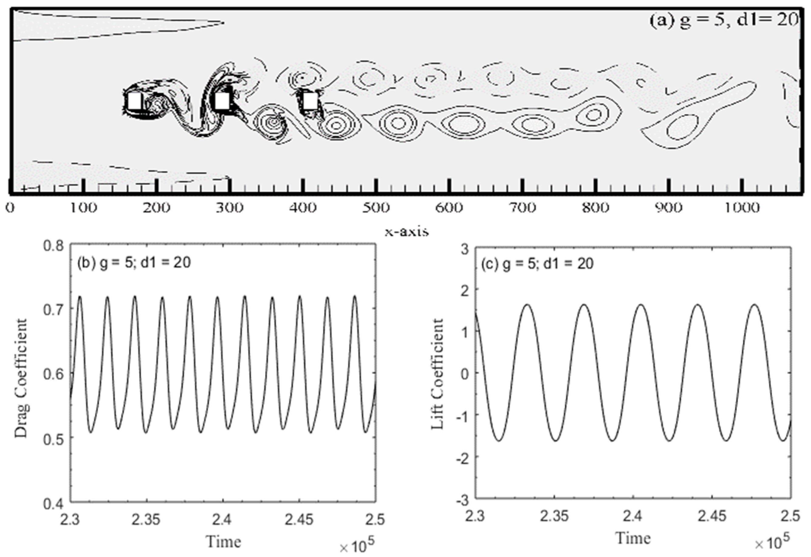
5.1.7. Two Rows Vortex Street (TRVS) Flow Mode

The last existing flow mode was named as two rows vortex street (TRVS) flow mode observed at (g, d1) = (5, 20). At this gap spacing and size of control rods, the flow finds enough space within the gaps for the complete development of vortices. In this flow mode the vortices move in a double row towards downstream of the computational domain. From Figure 9a, it can be seen that the shear layer separated from the upstream control rod and the middle main rod rolls up to form vortices between the gaps. These vortices are converted in two rows after interacting with the downstream control rod. Figure 9b,c shows the time signal analysis of Cd and Cl for two rows vortex street flow mode. It is clear from the figure that both the drag and lift graphs exhibit periodic behavior. Similarly, two rows vortex street flow mode was also reported by Islam et al. [32] for flow over three tandem square rods at g ≥ 5.

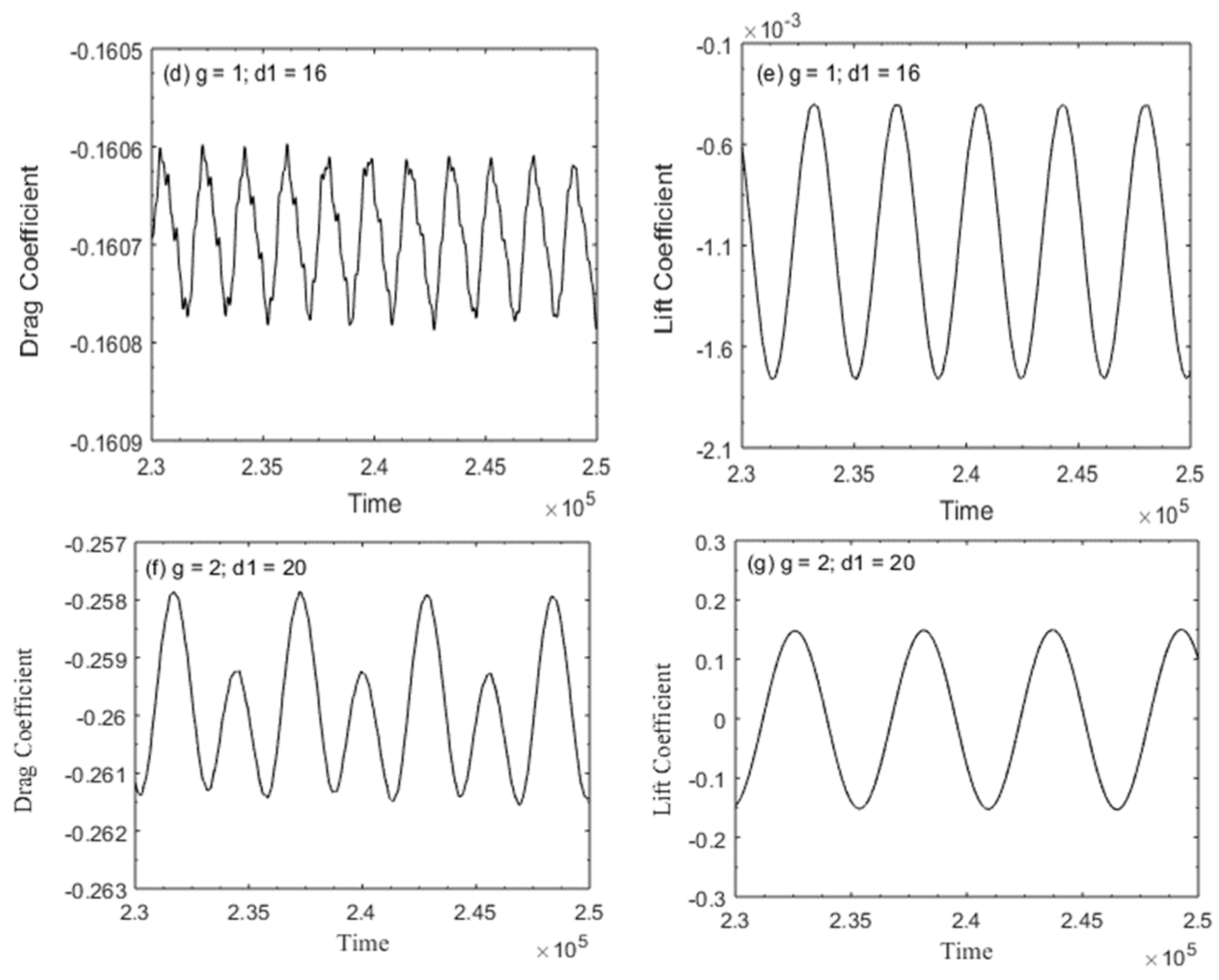
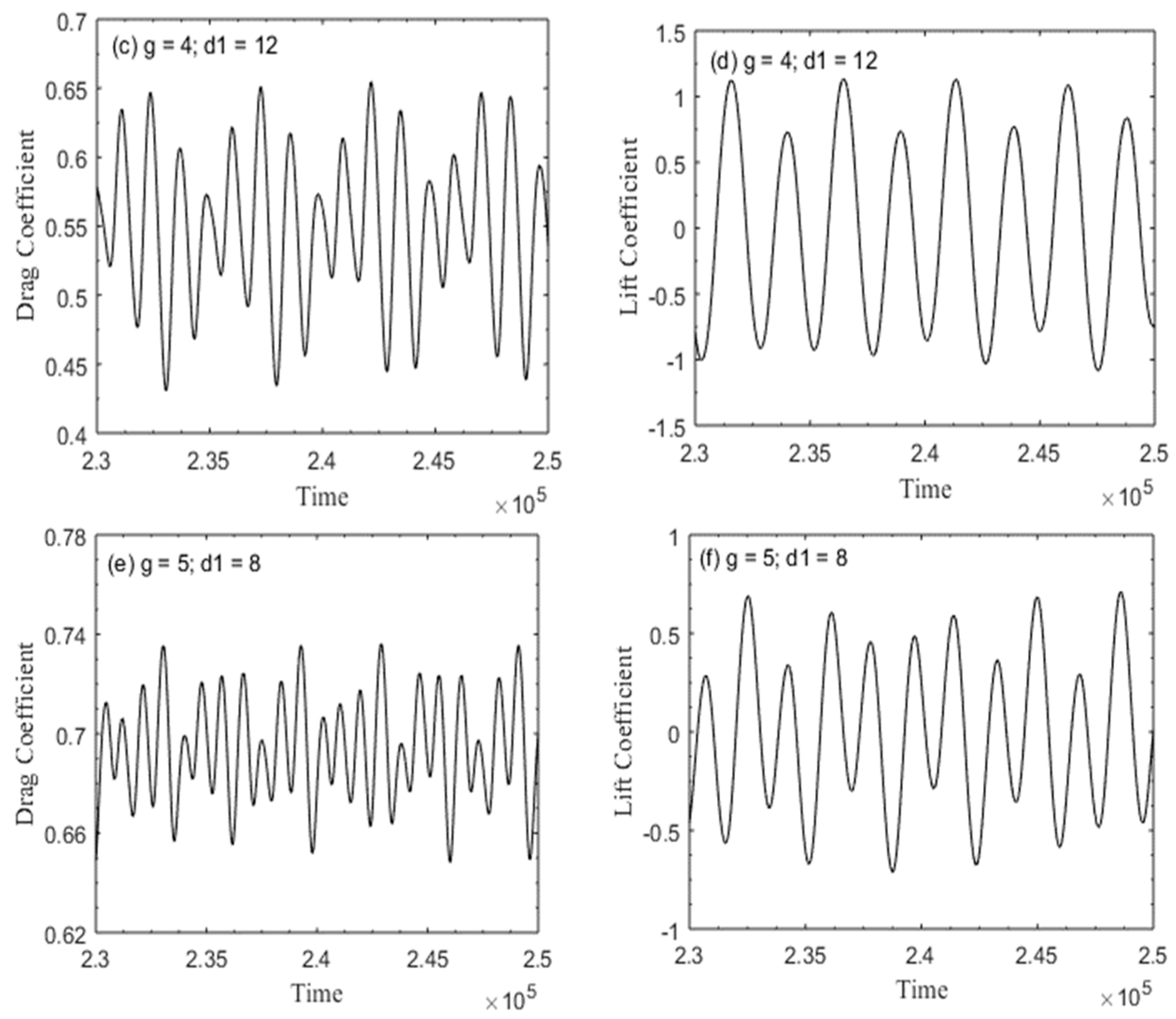
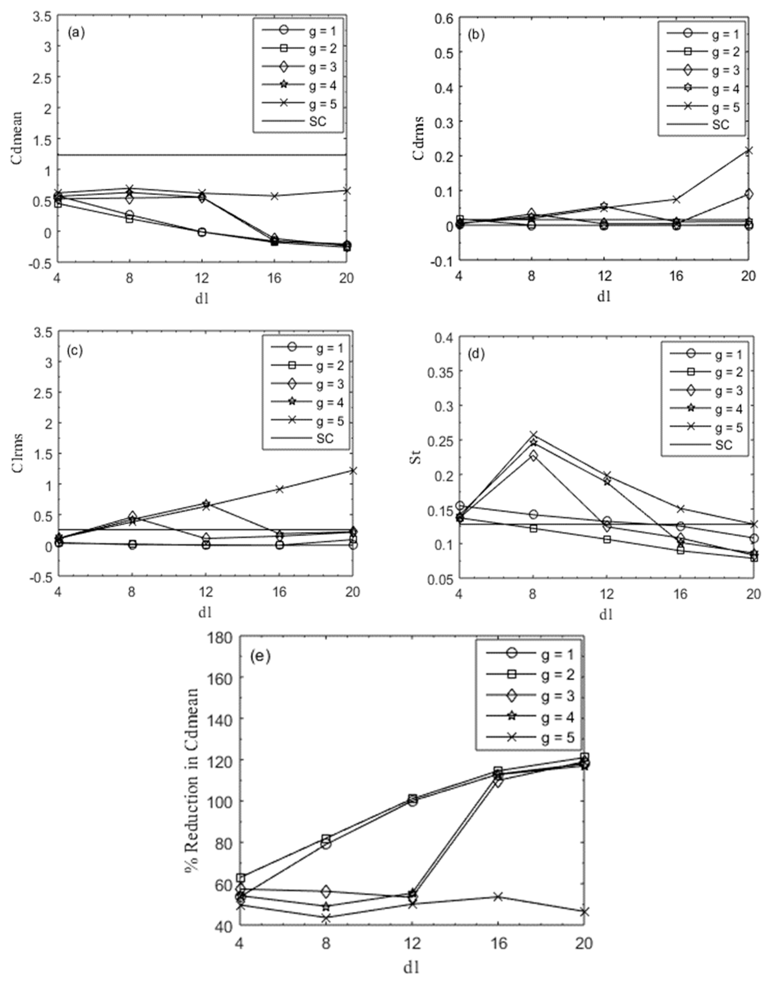
5.2. Force Statistics

The effect of different sizes of control rods at fixed Reynolds number on force statistics, such as mean of drag coefficient, root-mean-square of drag and lift coefficients, and Strouhal number at g = 1–5 and d1 = 4–20 is discussed in this section. Figure 10a–e shows the values of Cdmean, Cdrms, Clrms, St, and percentage reduction in Cdmean as a function of size of control rods for different values of gap spacings along with single square rod results. It is noticed that mean drag coefficient attains its local maxima at (g, d1) = (5, 8), where FDVS flow mode was observed. Due to enough space between the control rods and main rod, vortex shedding completely generated in-between the gap and vortices fully developed. Due to this, maximum drag force produced at this value of g and d1. It is observed from Figure 10a that Cdmean contains some negative values at (g, d1) = (1, 12), (1, 16), (1, 20), (2, 12), (2, 16), (2, 20), (, 16), (3, 20), (4, 16), and (4, 20). This indicates that negative pressure force is applied at these combinations of g and d1 on the main rod in the form of thrust. Harichandan and Roy [33] reported negative drag values in the case of three in-line circular rods, while Abbasi et al. [34] observed in the case of three in-line square rods. The minimum value of Cdmean was investigated at (g, d1) = (2, 20), which is −0.2587, where WSLR flow mode exists. It is due to the reason that, at d1 = 20, the size of the control rod becomes equal to the main rod and all the rods are near to each other at g = 2. Therefore, the control rods strongly effects the main rod against the generation of vortex shedding in-between the gap. Hence weak vortex shedding was produced at that point. Furthermore, the Cdmean at g = 1 and 2 decreased with increment in size of the control rod, but at g = 5, Cdmean continually increased with the size of the control rod. It is important to mention here that the Cdmean of the main rod for different combinations of g and d1 did not exceed the values of a single square rod without control rods (see Figure 10a). This indicates that the control rods reduce the drag force exerting on the main rod.
The Cdrms values are shown in Figure 10b for different values of g and d1. For d1 = 4–20, the Cdrms values are approximately equal to each other from g = 1–3, but for g = 4 and 5, Cdrms values increase at the largest size of control rods. This is due to the irregular shape and size of vortices at maximum values of g and d1. The minimum value of Cdrms attained at (g, d1) = (2, 12) is 0.0000583, where SF mode exists due to streamline flow behavior; while its maximum value occurred at (g, d1) = (5, 20) which is 0.2170, where the observed flow mode was TRVS. At maximum values of g and d1, the effect of control rods on the main rod diminished. Therefore, control rods generated their own frequency, that mixed up with frequency along with the frequency of main rod and vortices started to move in two rows. The Cdrms value of a single rod is 0.0162 which is less than the present Cdrms value for all the selected gap spacing (see Figure 10b).
The Clrms values represented a mixed trend by increasing the size of the control rod for g = 2, 3, and 4, but at g = 5, Clrms values increase with increment in size of the control rod. It is because, when control rods are far away from the main rod, then their influence on the main rod reduces and vortices with maximum magnitude develop. The least value of Clrms is 0.000237 and occurred at (g, d1) = (2, 12), at which SF mode appeared. The largest value of Clrms is 1.2219 and occurred at (g, d1) = (5, 20), where the existing observed flow mode is TRVS. The root-mean-square values of lift coefficient for g = 1, is less than the single rod value.
The Strouhal number, which indicates the primary vortex shedding frequency is shown in Figure 10d as a function of d1 for various g. It is clear from the figure that the St values of a single rod without a control rod are smaller than the St values of a main rod detached with controlling rods. The Strouhal number attains its local minimum value of 0.0787 investigated at (g, d1) = (2, 20), where WSLR flow mode was observed and local maximum value of 0.2571 at (g, d1) = (5, 8), where existing flow mode fully developed into vortex shedding flow mode. The St values for g = 3, 4, and 5, first increase then start decreasing with an increase in values of control rod size, but for g = 1 and 2, St continually decreases.
The percentage reduction in Cdmean against the size of the control rod for gap spacing g = 1–5 is shown in Figure 10e. It is deduced from the figure that the percentage reduction of Cdmean curves show increasing behavior at g = 1 and 2 for all sizes of control rods but with a mixed trend for the remaining values of gap spacing. This indicates that maximum reduction in drag is observed at the smallest values of gap spacing. The minimum reduction of 43.6% is examined at (g, d1) = (5, 8). This is due to the fact that at large g, the effect of the control rod diminishes. The maximum percentage reduction of 121% in drag force is observed (g, d1) = (2, 20), where without rolled up shear layer flow mode is characterized. The maximum reduction in Cdmean confirms that the maximum size of both upstream and downstream control rod reduces more drag force at small gap spacing as compared to the smaller size of control rods and without rolled up shear layer flow mode is an ideal flow mode for the present numerical investigation. The complete details of all existing flow modes are shown in Figure 11.

6. Conclusions

In this study, numerical computations are performed to examine the effect of size of control rods and gap spacing on the flow around a square rod in the presence of two small control rods aligned in-line. The gap spacing and size of control rods varied between g = 1–5 and d1 = 4–20, respectively. The adopted numerical technique for the present study is the LBM. The flow structure mechanism and aerodynamic forces are discussed in the form of vortex shedding, time-signals of Cd and Cl, and force statistics. The code for the present problem is validated against experimental and numerical data available in literature. The results obtained from the present study show good agreement with the results obtained from Vamsee et al. [12], Igarashi and Suzuki [29], Zdravkovich [31], Islam et al. [32], Harichandan and Roy [33], and Abbasi et al. [34]. Some concluding points of this study are as follows:
(1)
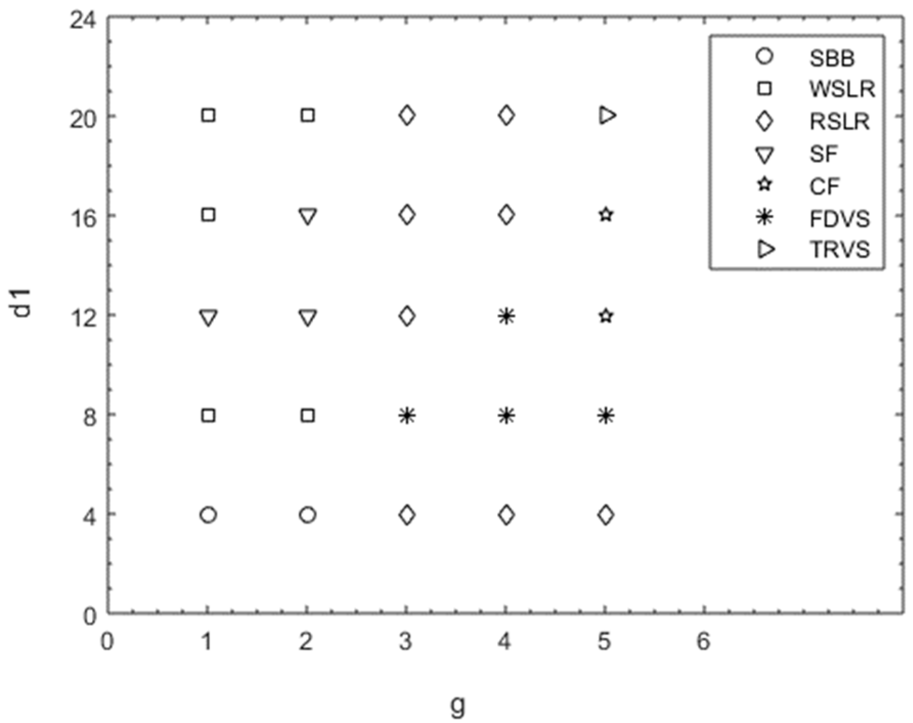
By varying g and d1, seven different flow modes were observed in this study: (i) single bluff body; (ii) without rolled up shear layer reattachment; (iii) rolled up shear layer reattachment; (iv) steady flow; (v) fully developed vortex street; (vi) critical flow; and (vii) two row vortex street flow modes.
(2)
The vortex shedding is completely suppressed at (g, d1) = (1, 12), (2, 12), and (2, 16) for steady flow mode.
(3)
It is observed that at highest gap spacing, that is g = 5, the effect of the control rods on the main rod vanishes. As a result, maximum values of Cdmean and St are investigated at (g, d1) = (5, 8).
(4)
It is found that the main rod experiences a negative drag force at (g, d1) = (1, 12), (2, 12), (1, 16), (2, 16), (3, 16), (4, 16), (1, 20), (2, 20), (3, 20), and (4, 20) due to the effect of thrust.
(5)
The maximum reduction in Cdmean was 121%, examined at (g, d1) = (2, 20) and minimum reduction at (g, d1) = (5, 8), which was 43.6%. Therefore, it was concluded that the maximum size of control rods with a moderate gap spacing plays an important role for reducing more drag force and suppress vortex shedding as compared to maximum gap spacing with small sizes of control rods.
(6)
The present numerical study shows that the lattice Boltzmann method is an effective technique to solve the problems of flow behind bluff bodies.

Author Contributions

Formal analysis, A.K. and K.S.N.; Funding acquisition, R.M. and D.B.; Investigation, R.M., I.K. and S.-U.-I.; Methodology and D.B., A.K. and K.S.N.; Resources, S.-U.-I.; Software, I.K.; Supervision, S.-U.-I. All authors equally contributed. All authors have read and agreed to the published version of the manuscript.

Funding

This research received no external funding.

Acknowledgments

No specific acknowledgment.

Conflicts of Interest

The authors declare no conflicts of interest.

Nomenclature

Cdcomponent of drag force
Clcomponent of lift force
Cdmeanmean drag coefficient
Cdrmsroot-mean-square value of drag coefficient
Clrmsroot-mean-square value of lift coefficient
dsize of main rod
d1size of control rods
Fdin-line force component
fiparticle density distribution function
fi(eq)particle equilibrium distribution function
Fltransverse force component
fsvortex shedding frequency
gspacing value
Lddownstream distance
Luupstream distance
ReReynolds number
sdistance between main rod and control rods
StStrouhal number
Uuniform inflow velocity
Qnumber of particles
Greek Symbols
ωiweighting coefficients
τstability parameter
νkinematic viscosity
ρdensity of fluid particle

References

  1. Mittal, S.; Raghuvanshi, A. Control of vortex shedding behind circular rod for flows at low Reynolds numbers. Int. J. Numer. Methods Fluids 2001, 35, 421–447. [Google Scholar] [CrossRef]
  2. Zhao, M.; Cheng, L.; Teng, B.; Liang, D.F. Numerical simulation of viscous flow past two circular rods of different diameters. Appl. Ocean Res. 2005, 27, 39–55. [Google Scholar] [CrossRef]
  3. Turki, S. Numerical simulation of passive control on vortex shedding behind square rod using splitter plate. Eng. Appl. Comput. Fluid Mech. 2008, 2, 514–524. [Google Scholar]
  4. Kuo, C.H.; Chen, C.C. Passive control of wake on by two small control rods at Reynolds number. J. Fluids Struct. 2009, 25, 1021–1028. [Google Scholar] [CrossRef]
  5. Malekzadeh, S.; Sohankar, A. Reduction of fluid forces and heat transfer on a square rod in a laminar flow regime using a control plate. Int. J. Heat Fluid Flow 2012, 34, 15–27. [Google Scholar] [CrossRef]
  6. Ali, M.S.M.; Doolan, C.J.; Wheatley, V. Low Reynolds number flow over a square rod with a detached flat plate. Int. J. Heat Fluid Flow 2012, 36, 133–141. [Google Scholar] [CrossRef]
  7. Wu, H.; Sun, D.P.; Lu, L.; Teng, B.; Tang, G.Q.; Song, J.N. Experimental investigation on the suppression of vortex-induced vibration of long flexible riser by multiple control rods. J. Fluids Struct. 2012, 30, 115–132. [Google Scholar] [CrossRef]
  8. Bao, Y.; Tao, J. The passive control of wake flow behind a circular rod by parallel dual plates. J. Fluids Struct. 2013, 37, 201–219. [Google Scholar] [CrossRef]
  9. Gupta, A. Suppression of Vortex Shedding in Flow around Square Rod Using Control Rod; Department of Mechanical Engineering, Indian Institute of Technology: Kanpur, India, 2013; pp. 1–13. [Google Scholar]
  10. Islam, S.U.; Rahman, H.; Abbasi, W.S.; Noreen, U.; Khan, A. Suppression of fluid force on flow past a square rod with a detached flat plate at low Reynolds number for various spacing ratios. J. Mech. Sci. Technol. 2014, 28, 4969–4978. [Google Scholar] [CrossRef]
  11. Lu, L.; Liu, M.M.; Teng, B.; Cui, Z.D.; Tang, G.Q.; Zhao, M.; Cheng, L. Numerical investigation of fluid flow past circular rod with multiple control rods at low Reynolds number. J. Fluids Struct. 2014, 48, 235–259. [Google Scholar] [CrossRef]
  12. Vamsee, G.R.; de Tena, M.L.; Tiwari, S. Effect of arrangement of inline control plate on flow past square rod. Prog. Comput. Fluid Dyn. 2014, 14, 277–294. [Google Scholar] [CrossRef]
  13. Islam, S.U.; Rahman, H.; Abbasi, W.S.; Shahina, T. Lattice Boltzmann study of wake structures and force statistics for various gap spacings between a square rod with a detached flat plate. Arab. J. Sci. Eng. 2015, 40, 2169–2182. [Google Scholar] [CrossRef]
  14. Islam, S.U.; Manzoor, R.; Islam, Z.U.; Kalsoom, S.; Zhou, C.Y. A computational study of drag reduction and vortex shedding suppression of flow past a square rod in presence of small control rods. AIP Adv. 2017, 7, 045119. [Google Scholar] [CrossRef]
  15. Islam, S.U.; Manzoor, R.; Zhou, C.Y. Effect of Reynolds number on flow past a square rod in presence of multiple control rods at various gap spacings. Arab. J. Sci. Eng. 2017, 42, 1049–1064. [Google Scholar] [CrossRef]
  16. Islam, S.U.; Manzoor, R.; Khan, U.; Nazeer, G.; Hassan, S. Drag reduction on a square rod using multiple detached control rods. KSCE J. Civ. Eng. 2017, 22, 2023–2034. [Google Scholar] [CrossRef]
  17. Chen, S.; Doolen, G. Lattice Boltzmann method for fluid flows. Annu. Rev. Fluid Mech. 1998, 30, 329–364. [Google Scholar] [CrossRef] [Green Version]
  18. Wolf-Gladrow, D.A. Lattice-Gas Cellular Automata and Lattice Boltzmann Models-An introduction; Springer: Berlin/Heidelberg, Germany, 2005. [Google Scholar]
  19. Sukop, M.C.; Thorne, D.T. Lattice Boltzmann Modeling: An Introduction for Geoscientists and Engineers; Springer: Berlin/Heidelberg, Germany, 2006. [Google Scholar]
  20. Mohammad, A.A. Lattice Boltzmann Method: Fundamentals and Engineering Applications with Computer Codes; Springer: London, UK, 2011. [Google Scholar]
  21. Guo, Z.; Liu, H.; Luo, L.S.; Xu, K. A comparative study of the LBE and GKS methods for 2D near incompressible laminar flows. J. Comput. Phys. 2008, 227, 4955–4976. [Google Scholar] [CrossRef]
  22. Cheng, M.; Whyte, D.S.; Lou, J. Numerical simulation of flow around a square rod in uniform-shear flow. J. Fluids Struct. 2007, 23, 207–226. [Google Scholar] [CrossRef]
  23. Okajima, A. Strouhal of rectangular rods. J. Fluid Mech. 1982, 123, 379–398. [Google Scholar] [CrossRef] [Green Version]
  24. Norberg, C. Flow around rectangular cylinders: Pressure forces and wake frequencies. J. Wind Eng. Ind. Aerodyn. 1993, 49, 187–196. [Google Scholar] [CrossRef]
  25. Sohankar, A.; Davidson, L.; Norberg, C. Numerical simulation of unsteady flow around a square two-dimensional rod. In Proceedings of the Twelfth Australasian Fluid Mechanics Conference, Sydney, Australia, 10–15 December 1995. [Google Scholar]
  26. Robichuax, J.; Balachandar, S.; Vanka, S.P. Three-dimensional floquet instability of the wake of a square rod. Phys. Fluids 1999, 11, 560–578. [Google Scholar] [CrossRef]
  27. Abograis, A.S.; Alshayji, A.E. Reduction of Fluid Forces on a square rod in a laminar flow using passive control methods. In Proceedings of the COMSOL Conference in Boston, Boston, MA, USA, 9–11 October 2013. [Google Scholar]
  28. Zdravkovich, M.M. Review and classification of various aerodynamic and hydrodynamic means for suppressing vortex shedding. J. Wind Eng. Ind. Aerodyn. 1981, 7, 145–189. [Google Scholar] [CrossRef]
  29. Igarashi, T.; Suzuki, K. Characteristics of the flow around three circular rods arranged inline. Bull. JSME 1984, 27, 2397–2404. [Google Scholar] [CrossRef]
  30. Sewatkar, C.M.; Patel, R.; Sharma, A.; Agrawal, A. Flow around six in-line square rods. J. Fluid Mech. 2012, 710, 195–233. [Google Scholar] [CrossRef]
  31. Zdravkovich, M.M. Review of flow interference between two circular rods in various arrangements. J. Fluids Eng. 1977, 99, 618–633. [Google Scholar] [CrossRef]
  32. Islam, S.U.; Abbasi, W.S.; Rahman, H.; Naheed, R. Numerical investigation of wake modes for flow past three tandem rods using the multi-relaxation-time lattice Boltzmann method for different gap spacings. J. Braz. Soc. Mech. Sci. Eng. 2016, 36, 799–812. [Google Scholar] [CrossRef]
  33. Harichandan, A.B.; Roy, R. Numerical investigation of low Reynolds number flow past two and three circular rods using unstructured grid CFR scheme. Int. J. Heat Fluid Flow 2010, 31, 154–171. [Google Scholar] [CrossRef]
  34. Abbasi, W.S.; Islam, S.U.; Rahman, H.; Manzoor, R. Numerical investigation of fluid-solid interaction for flow around three square rods. AIP Adv. 2018, 8, 025221. [Google Scholar] [CrossRef]
Figure 1. Two-dimensional nine particles velocity (D2Q9) model.
Symmetry 12 00475 g001
Figure 2. Schematic diagram for flow over a square rod detached with upstream and downstream control rods.
Symmetry 12 00475 g002
Figure 3. (a,b) Vorticity contours and (cf) time history analysis of Cd and Cl for single bluff body (SBB) flow mode.
Symmetry 12 00475 g003aSymmetry 12 00475 g003b
Figure 4. (ac) Vorticity contours and (dg) time history analysis of Cd and Cl for without rolled up shear layer reattachment (WSLR) flow mode.
Symmetry 12 00475 g004aSymmetry 12 00475 g004b
Figure 5. (ac) Vorticity contours and (dg) time history analysis of Cd and Cl for rolled up shear layer reattachment (RSLR) flow mode.
Symmetry 12 00475 g005
Figure 6. (a,b) Vorticity contours of steady flow mode.
Symmetry 12 00475 g006
Figure 7. (a,b) Vorticity contours and (c,d) time history analysis of Cd and Cl for critical flow (CF) mode.
Symmetry 12 00475 g007aSymmetry 12 00475 g007b
Figure 8. (a,b) Vorticity contours and (cf) time history analysis of Cd and Cl for fully developed vortex street (FDVS) flow mode.
Symmetry 12 00475 g008aSymmetry 12 00475 g008b
Figure 9. (a) Vorticity contours and (b,c) time history analysis of Cd and Cl for two rows vortex street (TRVS) flow mode.
Symmetry 12 00475 g009
Figure 10. (ad) Analysis of force coefficients and (e) percentage reduction in Cdmean at fixed gap spacing by varying size of control rods at Re = 160.
Symmetry 12 00475 g010
Figure 11. All existing flow modes at g = 1–5 and d1 = 4–20.
Symmetry 12 00475 g011
Table 1. Effect of grid points on the physical parameters for flow over a square rod at Reynolds number (Re) = 160. Cdmean, mean drag coefficient; Cdrms, root-square-mean value of drag coefficient; Clrms, root-square-mean value of lift coefficient.
10 Points20 Points40 Points
Cdmean1.211 (1.69%)1.2320 (2.3%)1.262
Cdrms0.019 (16.7%)0.0161 (8.2%)0.0150
Clrms0.2802 (9.8%)0.256 (7.1%)0.242
Table 2. Comparison of Cdmean and St for flow over a square rod at Re = 100 and 150.
ReCdmean (Re = 100)St (Re = 100)Cdmean (Re = 150)St (Re = 150)
Present1.48680.14991.5080.1549
Experimental [23]1.600.1411.4920.142
Experimental [24]1.5120.14021.4500.150
Numerical [25]1.4440.1451.4080.161
Numerical [26]1.540.1541.560.164
Numerical [27]1.4800.1401.4740.1528
Table 3. Selected cases for simulation at Re = 160.
CasesL × H (g = 1)L × H (g = 2)L × H (g = 3)L × H (g = 4)L × H (g = 5)
d1 = 4889 × 221929 × 221969 × 2211009 × 2211049 × 221
d1 = 8897 × 221937 × 221977 × 2211017 × 2211057 × 221
d1 = 12905 × 221945 × 221985 × 2211025 × 2211065 × 221
d1 = 16913 × 221953 × 221993 × 2211033 × 2211073 × 221
d1 = 20921 × 221961 × 2211001 × 2211041 × 2211081 × 221

