Article

Numerical Investigations on Magnetohydrodynamic Pump Based Microchannel Cooling System for Heat Dissipating Element

1
Department of Mechanical Engineering, Dong-A University, 37 Nakdong-Daero 550, Saha-gu, Busan 49315, Korea
2
Department of Mechanical and Mechatronics Engineering, University of Waterloo, 200 University Avenue West, Waterloo, ON N2L 3G1, Canada
*
Author to whom correspondence should be addressed.
Equal contribution.
Symmetry 2020, 12(10), 1713; https://doi.org/10.3390/sym12101713
Submission received: 17 September 2020 / Revised: 7 October 2020 / Accepted: 12 October 2020 / Published: 16 October 2020
(This article belongs to the Special Issue Heat Transfer in Engineering)

Abstract

:
Numerical investigations are performed on the magnetohydrodynamic (MHD) pump-based microchannel cooling system for heat dissipating element. In the present study, the MHD pump performance is evaluated considering normal current density, magnetic flux density, volumetric Lorentz force, shear stress and pump flow velocity by varying applied voltage and Hartmann number. It is found that for a low Hartmann number, the Lorentz force increases with an increase in applied voltage and Hartmann number. The velocity distribution along dimensionless width, the shear stress distribution along dimensionless width, the magnetic flux density along the dimensionless width and radial magnetic field distribution showed symmetrical behavior. The MHD pump-based microchannel cooling system performance is evaluated by considering the maximum temperature of the heat dissipating element, heat removal rate, efficiency, thermal field, flow field and Nusselt number. In addition, the influence of various nanofluids including Cu-water, TiO2-water and Al2O3-water nanofluids on heat transfer performance of MHD pump-based microchannel is evaluated. As the applied voltage increased from 0.05 V to 0.35 V at Hartmann number 1.41, the heat removal rate increased by 39.5%. The results reveal that for low Hartmann number, average Nusselt number is increasing function of applied voltage and Hartmann number. At the Hartmann number value of 3.74 and applied voltage value of 0.35 V, average Nusselt numbers were 12.3% and 15.1% higher for Cu-water nanofluid compared to TiO2-water and Al2O3-water nanofluids, respectively. The proposed magnetohydrodynamic microcooling system is effective without any moving part.

1. Introduction

Magnetohydrodynamic (MHD) pumps have been focus of research owing to various advantages over traditional pumps in many specific areas of application including biological fields, solar applications and heat transfer systems [1]. The major advantage of such pumps is that they are free of any moving parts. Additionally, the miniaturization of such pumps due to their simple structure, can be utilized in microfluidic systems, microcooling systems and microelectromechanical system (MEMS) applications [2,3]. In a few applications, where it is difficult to use conventional pumps such as molten metal pumping, these pumps are more useful and efficient. Moreover, the applications requiring no moving sections, for example, in spaceships and biological applications like blood pumping, these pumps can be used [4]. Out of various applications, one of the promising usages of MHD pumps is cooling of heat dissipating element. The coolant flow is generated by MHD pumps and can be made to flow in the microchannel where the dissipated heat from the heat dissipating element is taken away. Use of microchannels in a cooling system is one of the efficient ways of dissipating heat [5,6]. In such instances, heat transfer effectiveness and the thermal behavior of a cooling system with its influencing factors need to be investigated.
Lemoff et al. [7] developed and presented one of the first MHD micropumps with AC current using Lorentz force to pump electrolytic solution in microchannel. The authors showed that the continuous flow without any pulse can be produced. Rivero and Cuevas [8] studied MHD micropumps in one and two-dimensional flow models for laminar flows in parallel plates and rectangular ducts by considering the influence of slip condition which can be used to design MHD micropumps and characterize the flow behavior in these microfluidic devices. The 2D model presented by the authors showed more accuracy with results of experimentation as compared to 1D model [8]. Zhao et al. [9] conducted an analytical study by using the separation of variables method for generalized Maxwell fluids in a MHD rectangular micropump operated under the AC electric field and found that for given oscillating Reynolds number, large Hartmann number leads to large amplitudes of velocity. Yousofvand et al. [10] investigated heat transfer and pumping performance of electromagnetic pump considering Cu-water nanofluid as working fluid and found that for low Hartmann numbers, body force increases whereas for Ha > 200, the opposite trend is observed. Moghaddam analytically investigated the MHD micropump performance considering circular channel. The author found that average dimensionless velocity initially increases with increase in Hartmann number and dimensionless radius. However, after attaining peak, the average dimensionless velocity decreases with increase in Hartmann number and dimensionless radius [11]. Miroshnichenko et al. [12] studied MHD natural convection in a partially open trapezoidal cavity under the influence of various magnetic field orientations and found that an increase in uniform magnetic field value decreases the rate of heat transfer. A comprehensive study of power-law fluids in MHD natural convection has been conducted by Kefayati [13,14]. Shirvan et al. [15] conducted numerical investigations on MHD flow in a square cavity with different inlet and outlet ports. The authors presented optimization of mean Nusselt number using orthogonal array optimization. Kiyasatfar et al. [16] investigated thermal behavior and fluid motion in direct current (DC) MHD pump by varying magnetic flux density, applied current and channel size. The authors found that the maximum velocity increases with increase in applied current and as Hartmann number increases the velocity profile becomes flatter. Larimi et al. [17] studied the effect of non-uniform transverse magnetic field arrangements with a different Reynolds number for magnetic nanofluids on heat transfer and found that applying external magnetic fluid is strongly effective in fluid cooling at low Reynolds number. Kolsi et al. [18] performed a numerical study for 3D MHD natural convection inside a cubical enclosure with an inclined plate and found an optimal inclination angle of 180° for the plate. Kefayati considered various flow types including non-Newtonian nanofluids [19], blood flow [20] and power-law fluids in an internal flow [21] with focus of investigation on the effects of the power-law index, Reynolds number on thermal behavior by varying magnetic field to find optimized conditions. Further research has been conducted to understand the flow behavior of MHD considering different cases [22,23].
The MHD pump involves two types of heat transfer mechanism: forced convection and mixed convection. The micro-cooling of the heat dissipating element is a case of mixed convection owing to its microstructure and very low flow rate. Mixed convection heat transfer has attracted significant research attention of heat transfer engineers owing to various application fields including heat exchangers, electronic cooling [24], heat dissipating element cooling [25], micro-cooling, MEMS applications, solar energy applications and metal casting [26]. Micro-cooling application is one of the critical research areas which has gained importance due to recent trends of miniaturization of devices as well as high power applications, which results in large amount of heat generation in compact volume. The various cooling methods previously suggested, including direct fan cooling [27] and thermoelectric cooling, suffer from low efficiency and high-power consumption. In addition, the presence of moving components makes conventional cooling methods less desirable [28]. Therefore, in the present study, MHD pump-based microchannel cooling for a heat dissipating element is investigated. The MHD pump performance is evaluated by varying the applied voltage and Hartmann number, and its effect on various parameters including normal current density, magnetic flux density, volumetric Lorentz force, shear stress and pump flow velocity is reported. The heat transfer performance of the MHD pump-based microchannel cooling for a heat dissipating element is reported by considering the heat removal rate, efficiency, thermal field, flow field and Nusselt number. In addition, three different nanofluids, including Cu-water, TiO2-water and Al2O3-water, are considered, and their influence on heat transfer performance is compared. The comparative heat transfer performance and potentials of various nanofluids in MHD pump application for microchannel cooling have not been realized. This study provides a comprehensive understanding of MHD pump performance, heat transfer performance of MHD pump-based microchannel cooling systems, and the influence of various nanofluids on heat transfer performance.

2. Method

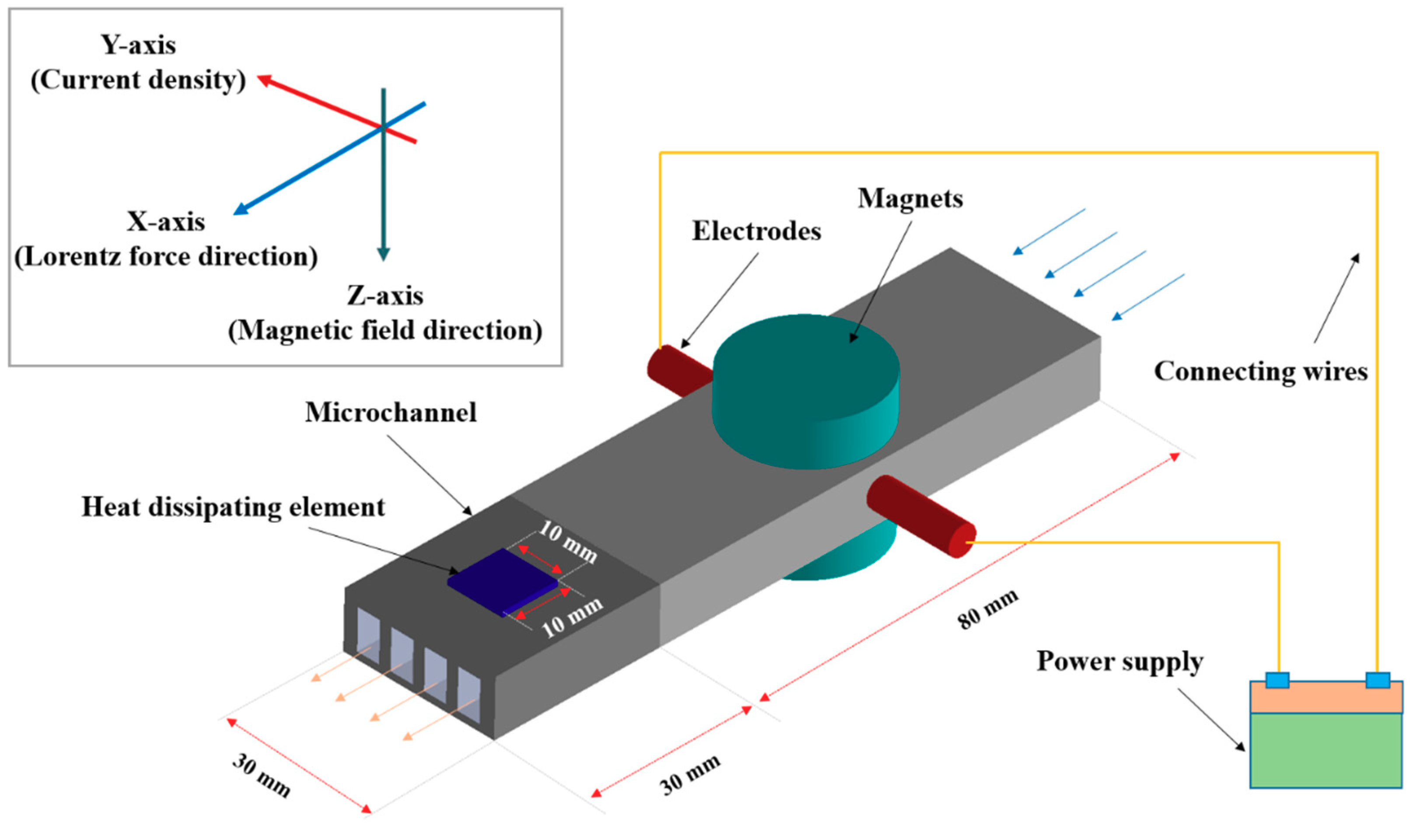
2.1. Numerical Modeling

A schematic view of an MHD pump for cooling a heat dissipating element is presented in Figure 1. A heat dissipating element can be any microsystem including microfluidic devices, micro-batteries, electronic chips, light emitting diodes (LED), etc. The basic principle of operation of MHD pumps is based on the Lorentz force in which magnetic and electrical fields are kept perpendicular, which forces conducting fluids in a perpendicular direction to both electric currents and magnetic fields, creating an MHD pump effect. The magnetic field strength and applied current both affect the flow velocity. The magnetic field is created by keeping two small permanent magnets. The origin of the coordinate system lies between two magnets and it is equidistance from the magnets. The origin of the coordinate system lies exactly at the center of the MHD pump without considering the microchannel dimensions (Figure 1). The origin of the coordinate system has been chosen specifically at the center of the MHD pump (without considering microchannel dimensions) for simplicity in the calculations. The width of the MHD pump is chosen as a characteristic length of the system considering width as an important dimension of the MHD pump system along which various parameters are evaluated. Due to the Lorentz force, the coolant flows in the positive X-axis direction (i.e., from the MHD pump and towards the microchannel) as shown in Figure 1. The microchannel consists of four slots. Details of the MHD pump dimensions are provided in Table 1.

2.2. Governing Equations and Boundary Conditions

The modeling of the MHD phenomena involves a multiphysics problem with coupled equations between fluid flow, heat transfer, current flow, and magnetic fields, which are solved numerically. The different fields of physics involved are expressed by partial differential equations, which can be solved via the finite element method. In the present study, the numerical modeling of the MHD phenomena is conducted using COMSOL. The partial differential equations involving multiphysics behavior with coupling between fluid flow, heat transfer, electric current and magnetics are solved using the finite element method. The fluid flow and heat transfer are governed by the Navier–Stokes equation as shown below [29]. Equations (1)–(3) show continuity, momentum and energy conservation, respectively [30], where V is velocity, ρ is density, p is pressure and α is thermal diffusivity.
· V = 0
( V · ) V = 1 ρ P + 2 V + 1 ρ F
( V · ) T = α 2 T
F = J × B
J = σ ( E + V × B )
F is the body force due to Lorentz forces which causes fluid motion as shown in Equation (4) [9]. The electric current density which is defined by Ohm’s law is shown in Equation (5) [31], where J is the electric current in y-direction and B is the magnetic field in the z-direction. The electric current and magnetic field are perpendicular which creates a Lorentz force in the x-direction.
The working fluid is Newtonian fluid with flow considered as steady and laminar based on the low Reynolds number. The thermo-physical properties of working fluid, nanoparticle and boundary conditions are presented in Table 2. The heat dissipating element that is acting on the pump’s wall is assumed to be a constant volumetric heat generation source. The applied electric voltage is varied from 0.05 V to 0.35 V with an interval of 0.05 V. The Hartmann number is varied from 1.41 to 3.74. The cylindrical type permanent magnets are used for providing the magnetic field intensity. Three different types of nanofluids are considered including Cu-water, TiO2-water, and Al2O3-water nanofluids. The base fluid for all the nanofluids is water. The boundary condition of opening at atmospheric pressure is applied at the coolant inlet and coolant outlet. The density of water is considered as 997.0 kg/m3 at 25 °C and assumed as an incompressible fluid. The thermal conductivity of water is considered as 0.6069 W/m-K at 25 °C. The specific heat of water is considered as 4181.7 J/kg-K. The details about the boundary conditions and thermophysical properties of water and nanoparticles are presented in Table 2.

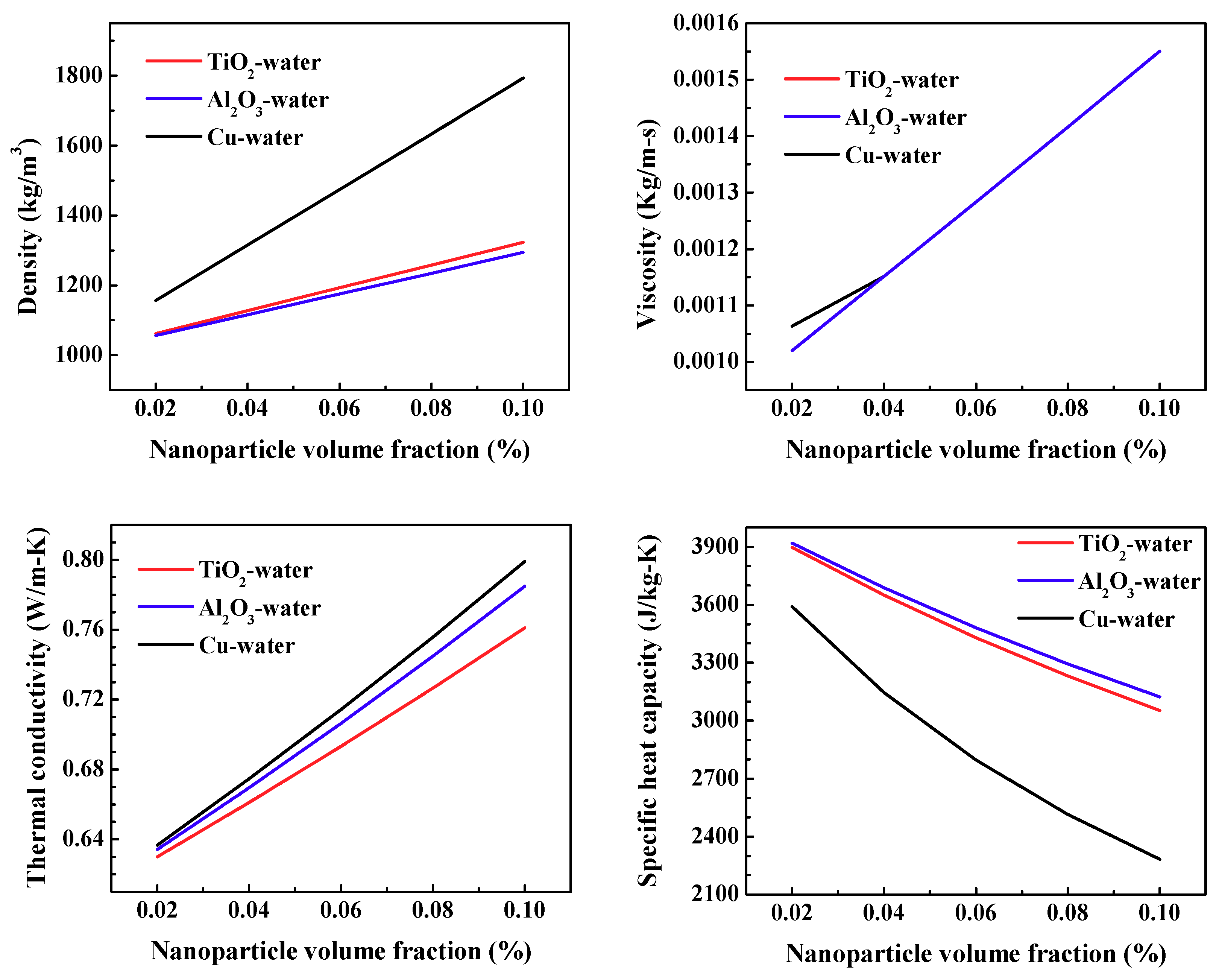
2.3. Nanofluid Relations

The density of nanofluid with various nanoparticle volume fraction is predicted by the Pak et al. [34] as shown in Equation (6). Zhong et al. [35] experimentally measured the density of TiO2-water nanofluid and compared the predictions using the Equation (6) within 0.54%. Therefore, in the current study, the density of various nanofluids with different volume fraction is calculated using Equation (6), where ρ denotes density and   ϕ denotes volume fraction.
ρ nf = ϕ ρ n + ( 1 ϕ ) ρ f
The viscosity of the nanofluid ( μ nf ) with various nanoparticle volume fraction ( ϕ ) using viscosity of fluid ( μ f ) is predicted by various researchers including Batchelor [36], Vand [37], Wang et al. [38], Duangthongsuk et al. [39] and Bobbo et al. [40], as shown in Equations (7)–(11), respectivelyBased on the model prediction accuracy with experimental data [35], in the present study, the model proposed by Want et al. [38] is used for calculating the viscosity of nanofluid.
μ nf = μ f ( 1 + 2.5 ϕ + 6.5 ϕ 2 )
μ nf = μ f ( 1 + 2.5 ϕ + 7.349 ϕ 2 )
μ nf = μ f ( 1 + 7.3 ϕ + 123 ϕ 2 )
μ nf = μ f ( 1.013 + 0.092 ϕ 0.015 ϕ 2 )
μ nf = μ f ( 1 + 0.36838 ϕ + 0.25271 ϕ 2 )
The thermal conductivity and specific heat of nanofluid for various volume fractions are calculated using Equation (12) [41] and Equation (13) [42], respectively. The effect of the nanoparticle volume fraction on the mixture properties is presented in Figure 2.
k nf = k f k p + 2 k f + 2 ϕ ( k p k f ) k p + 2 k f 2 ϕ ( k p k f )
( ρ C p ) nf = ( 1 ϕ ) ( ρ C p ) f + ϕ ( ρ C p ) n

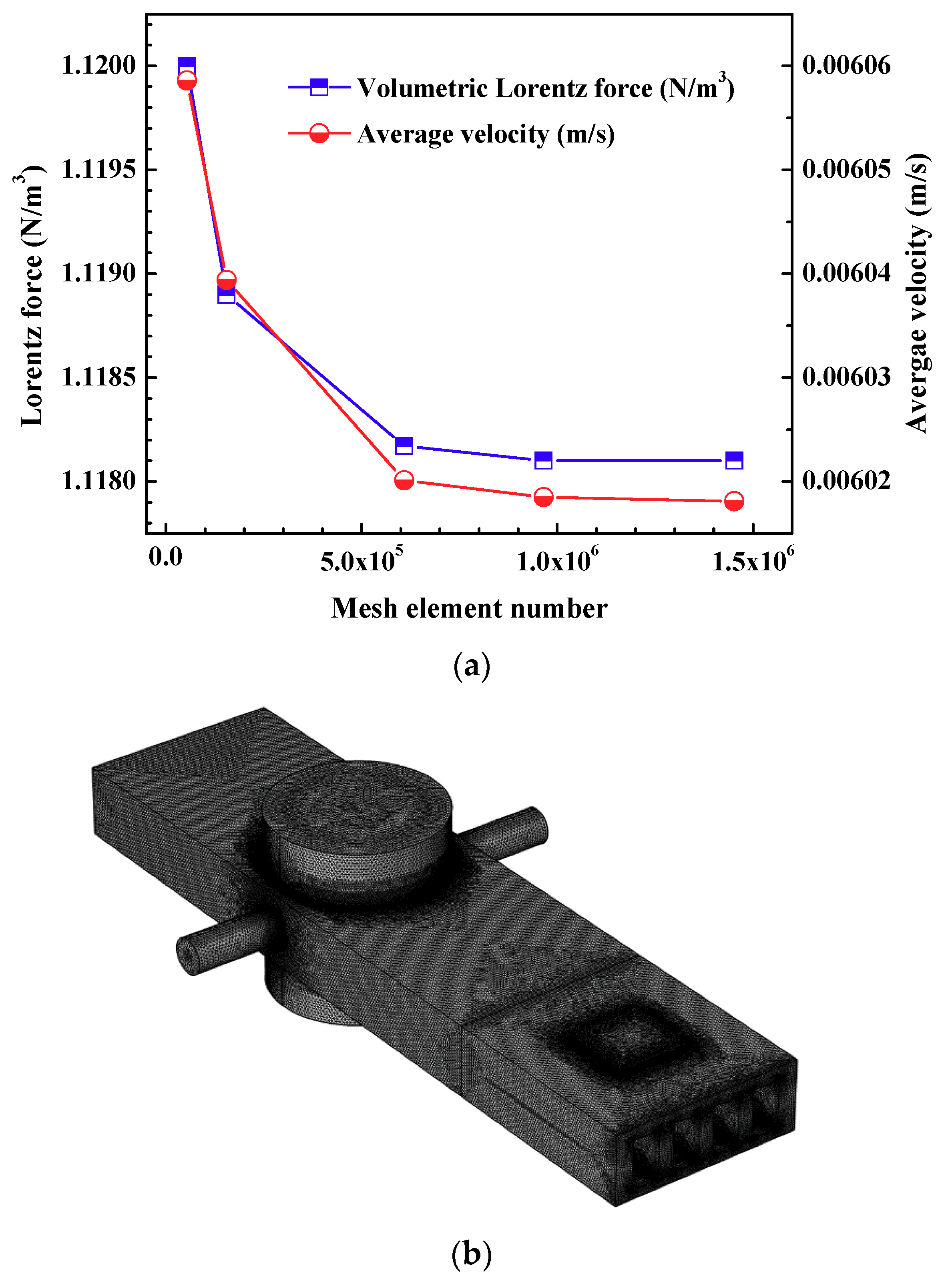
2.4. Mesh Independency

Figure 3 shows the details of the mesh independency test. The Lorentz force and average velocity are considered as parameters to evaluate the mesh independency. In the present study, the mesh type is defined as the number of elements in the generated mesh. Mesh type 1 contains 5.43 × 10⁴ elements, which is a coarse mesh, whereas mesh type 5 contains 1.45 × 10⁶ elements, which is a finer mesh. As the mesh elements increased from 9.65 × 10⁵ to 1.45 × 10⁶, the Lorentz force and average velocity varied only 0.008% and 0.166%, respectively. Considering the computational cost and accuracy of the numerical simulations, mesh type 4 with 9.65 × 10⁵ elements, is selected for carrying out numerical simulations as shown in Table 3.

2.5. Data Reduction

The MHD pump flow is generated by the application of electric and magnetic field, which interacts with the conducting fluid. The developed flow is described as Hartmann flow and the non-dimensional number, known as the Hartmann number (Ha), is defined as shown in Equation (14), where B is magnetic flux intensity, L is characteristics length, σ is electrical conductivity and μ is dynamic viscosity [21]. The Hartmann number gives an estimation of the magnetic forces compared to viscous force [9].
Ha = BL ( σ / μ ) 0.5
The convective heat transfer rate is used to obtain heat transfer coefficient and calculate average Nusselt number (Nuavg). The heat transfer rate is evaluated as shown in Equation (15) [43].
Q conv = m in C p ( T bulk , out T bulk , in )
The average heat transfer coefficient is evaluated from Equation (16). The numerator is convective heat transfer from wall to fluid and the denominator is a combined term consisting of the wall convective surface area and logarithmic mean temperature difference of the wall-and-bulk fluid [25].
h avg = Q conv A wall ( T wall T bulk ) LMTD
( T wall T bulk ) LMTD = Δ T wall - buk , in Δ T wall - buk , out log ( Δ T wall - buk , in / Δ T wall - buk , out )
where Δ T wall - buk , in and Δ T wall - buk , out indicate the differences between the wall temperature and bulk fluid temperature at the inlet and outlet of the channel, respectively (Equation (17)). The average Nusselt number is calculated as shown in Equation (10) where Dh represents the hydraulic diameter and kf represents the thermal conductivity of the fluid.
Nu avg = h avg × D h k f

3. Results and Discussion
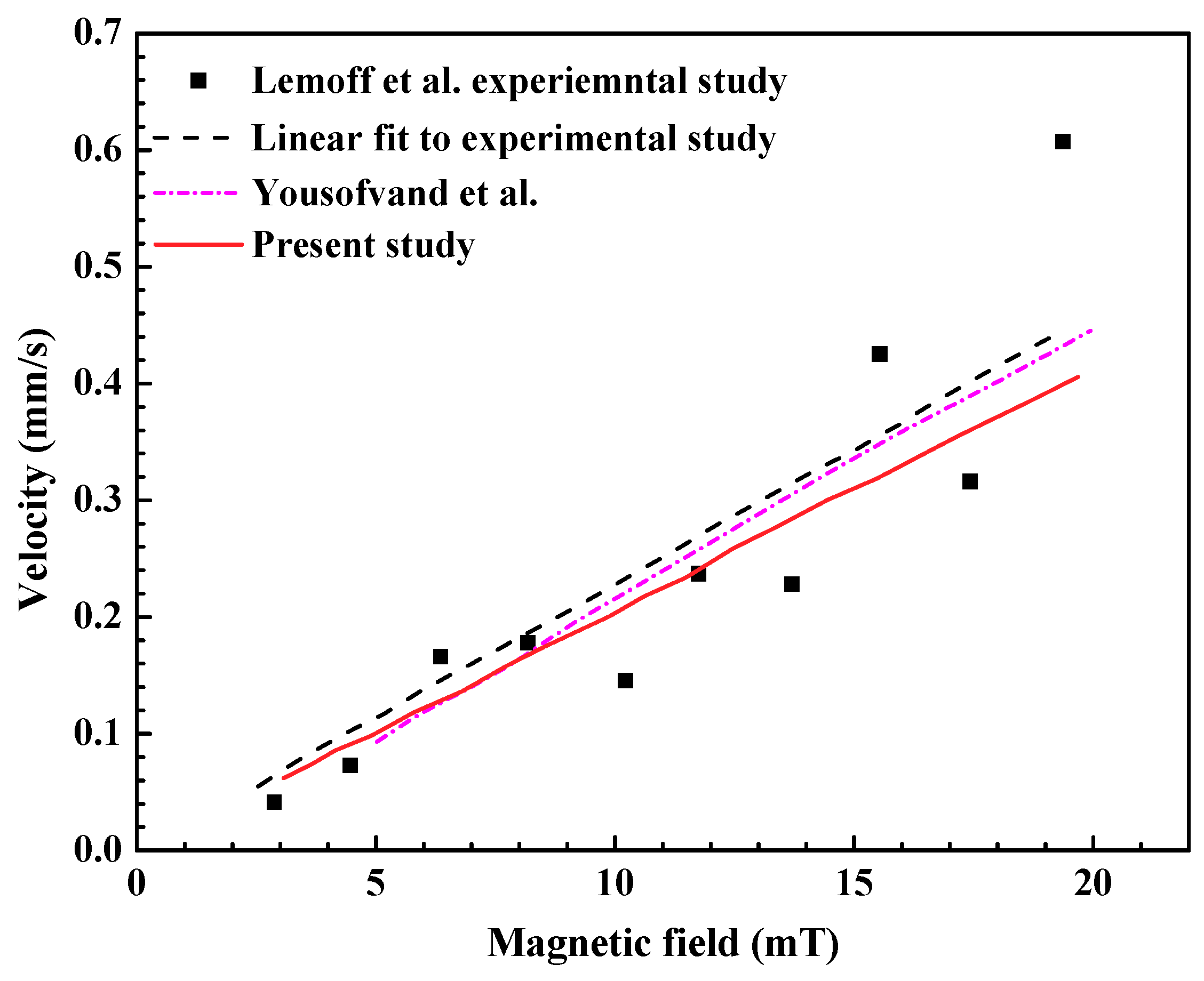
The results of the numerical study on the MHD pump subjected to the mentioned boundary conditions are presented in terms of normal current density, magnetic flux density, volumetric Lorentz force, shear stress and pump flow velocity by varying applied voltage and Hartmann number. For evaluating the MHD pump performance, Cu-water nanofluid with 0.1% volume fraction was considered. In the subsequent sub-sections, the performance of the MHD pump-based microchannel cooling system is presented considering various parameters, including the maximum temperature of a heat dissipating element, heat removal rate, efficiency, thermal field, flow field and Nusselt number. In addition, the heat transfer performance of Cu-water nanofluid is compared with TiO2-water nanofluid and Al2O3-water nanofluid. The study provided an in-depth understanding of the MHD pump functioning and its application in micro-cooling systems.

3.1. Validation

The numerical study is validated with the previously published literature. The server workstation with an Intel (R) Xenon(R) CPU E5-2620 v3 @2.40 GHz including 24 cores and 64 GB computation memory is used to run the simulations. To ensure the accuracy of the numerical study method, numerically predicted velocity is compared with previously published experimental data [7] and numerical data [10] as shown in Figure 4. It is demonstrated that the predicted velocity closely matches with the linear fit to the experimental data and numerical data. Thus, the validation of the numerical model is confirmed.

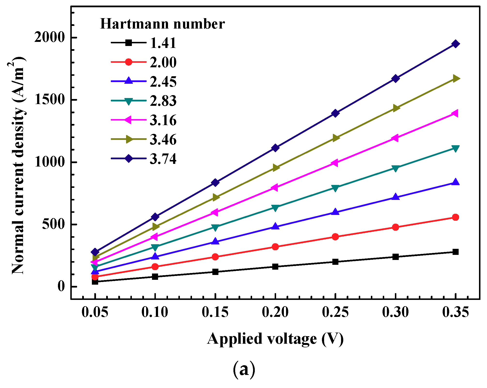
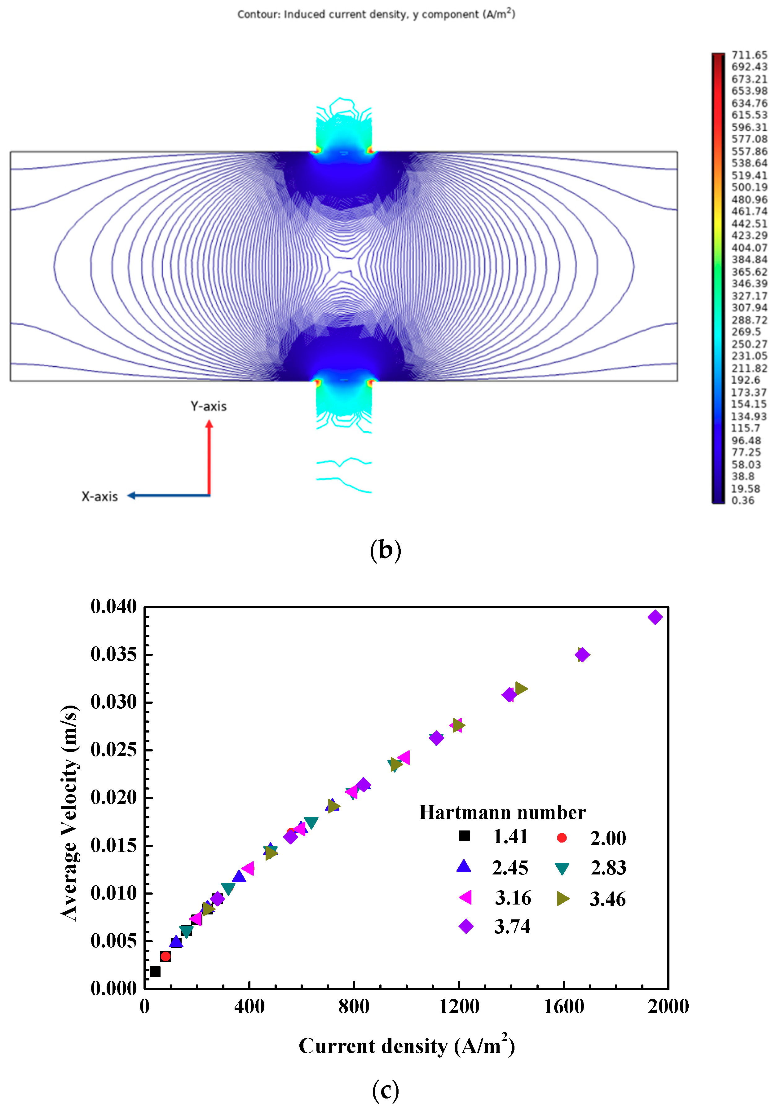
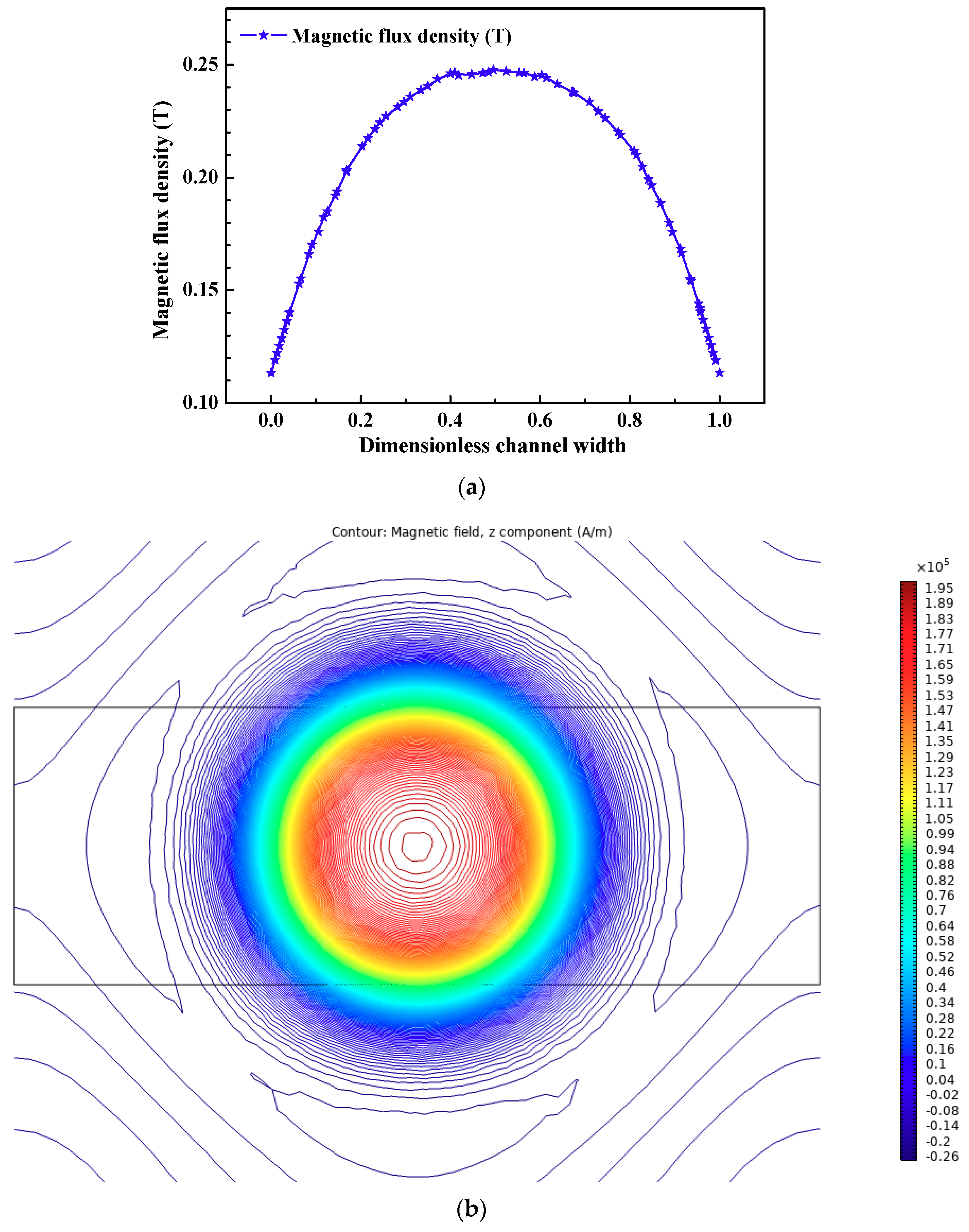
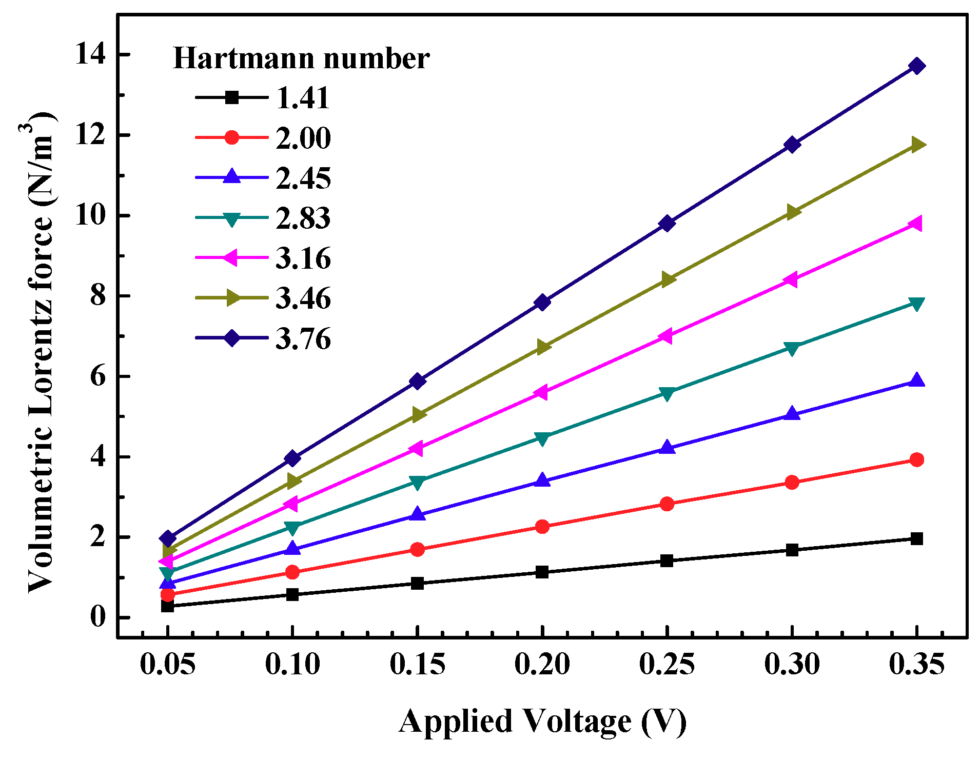
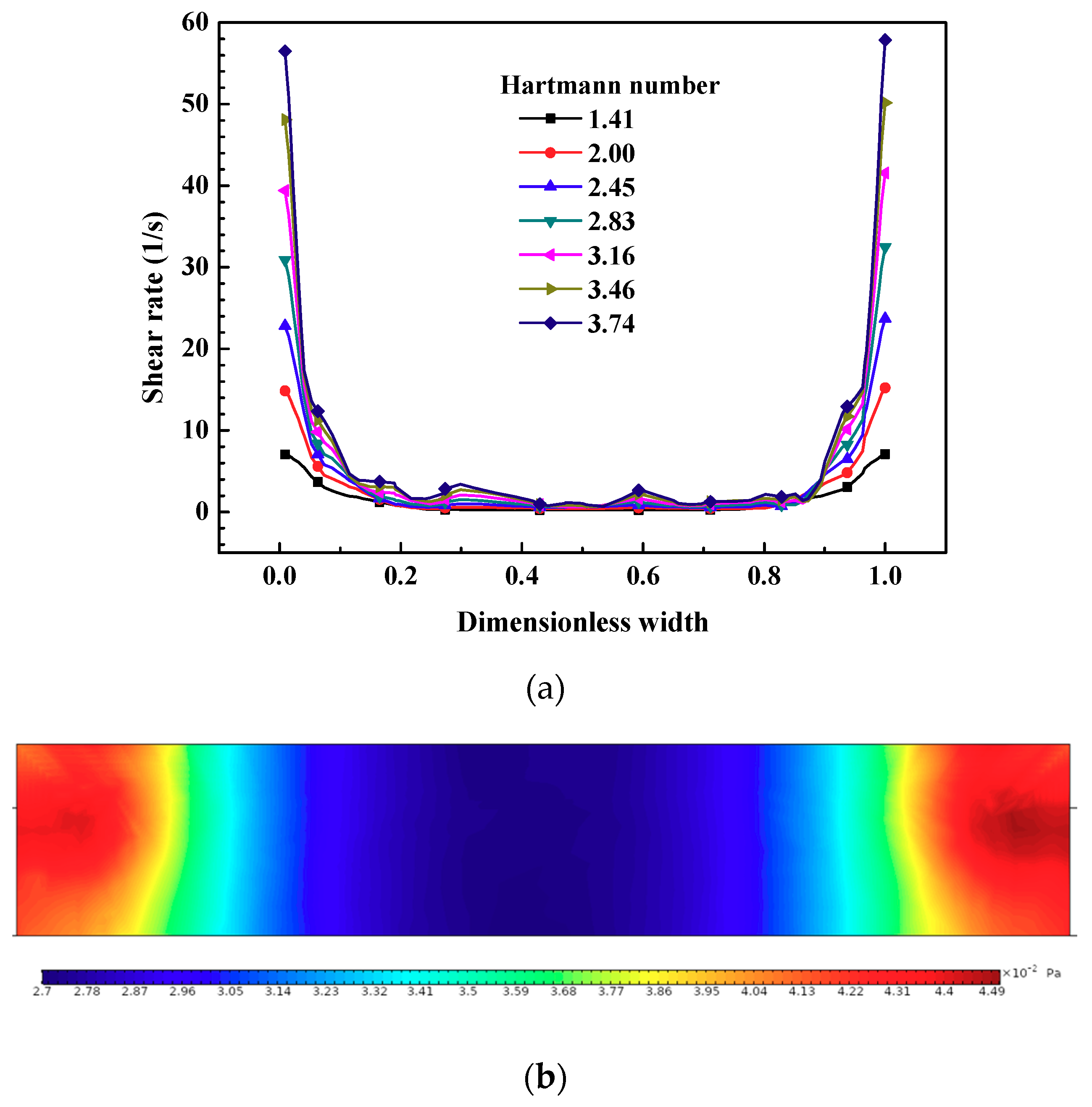
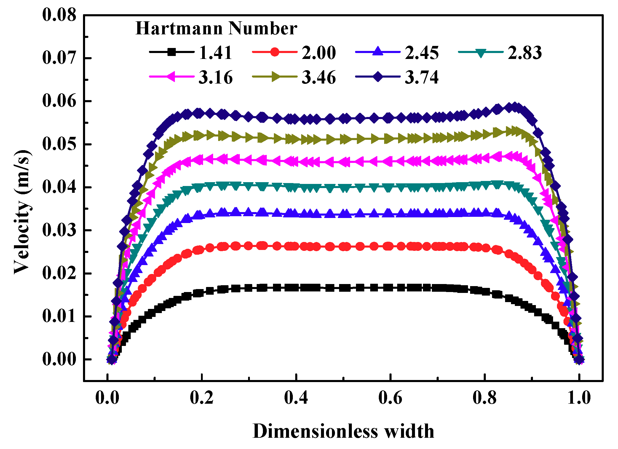
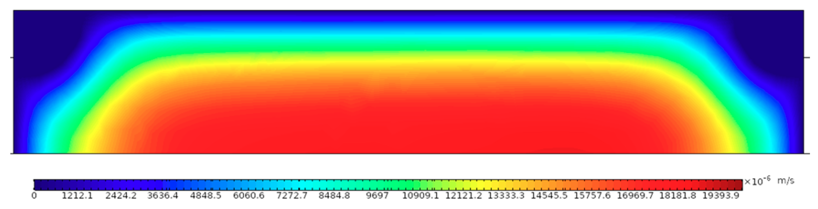
3.2. Magnetohydrodynamic Pump (MHD) Performance

Figure 5a shows the variation of normal current density with the applied voltage and Hartmann number. The normal current density increased with the increase in applied voltage. For example, as the applied voltage increased from 0.05 V to 0.35 V, at a Hartmann number value of 2.0, the normal current density increased 600%, or 6 times. For the same applied voltage, a higher normal current density is observed for the higher Hartmann number. As the Hartmann number increased from 1.41 to 3.76 at a constant applied voltage of 0.35 V, the normal current density increased 600%, or 6 times. The combined influence of a higher applied voltage and higher Hartmann number are visible with a significant increase in the normal current density.
Figure 5b shows the spatial variation of induced current and it can be seen that the induced current density is higher near electrode area. Figure 5c shows the variation of the average velocity with respect to current density. The average velocity increased linearly with the increase in current density. The flow rate can be increased either by increasing applied current, keeping magnetic flux constant or by increasing magnetic flux while keeping the applied current constant to enhance the pump performance. Similar trends have been observed by previously conducted studies [16]. For low Hartmann numbers, the velocity increased with an increase in the Hartmann number. However, the high Hartmann number can have a negative effect on the velocity as well as volumetric flow rate [11]. For a low Hartmann number, forced convection dominates with higher velocities which is useful for enhancing the pump performance.
Figure 6a shows the variation of magnetic flux along the dimensionless width in the Y-axis at the center of the magnetohydrodynamic pump. The maximum value of the magnetic flux attained is about 0.25 T at the center of the MHD pump channel. However, the value of the magnetic flux density near the conducting electrode is found to be in the order of 0.11 T. Similar results have been obtained by Aoki et al. [44]. The magnetic flux showed axisymmetric behavior for the axis passing through the center of the dimensionless width. Figure 6b shows the magnetic field distribution for the MHD pump on the XY-plane. As in the present study, the cylindrical permanent magnet is considered for the MHD pump application and the circular magnetic field pattern is observed. The maximum magnetic field value of the order of 100 kA/m is observed. The magnetic field showed radial symmetric behavior for the axis passing through the center of the magnet.
Figure 7 shows the volumetric Lorentz force variation for applied voltage and Hartmann number. The volumetric Lorentz force increased with increase in applied voltage. For example, as the applied voltage increased from 0.05 V to 0.35 V at a Hartmann number value of 2.0, the volumetric Lorentz force increased 600%, or 6 times. For the same applied voltage, a higher volumetric Lorentz force is observed for a higher Hartmann number. As the Hartmann number increased from 1.41 to 3.76, at a constant applied voltage of 0.35 V, the volumetric Lorentz force increased 600%, or 6 times. In the study conducted by Moghaddam on MHD micropumps, the volumetric flow rate increased owing to an increase in the Hartmann number to a value of 40, then volumetric flow rate started to decrease [11]. Similarly, the volumetric flow rate increased until a Hartmann number of 200, and then decreased in the study conducted on the MHD pump by Yousofvand et al. [10]. The present study is focused on low Hartmann numbers (Ha < 4) where the volumetric flow rate and Lorentz force increases with the increase in Hartmann number, as the defined Hartman number compares the magnetic force with the viscous force. At low Hartmann numbers, the viscous forces dominate giving a higher volumetric flow rate. As a result, the lower Hartmann number is favorable for the enhancement of heat transfer. However, a higher Hartmann number can have an adverse effect on heat transfer [10].
Figure 8a shows the shear stress variation along the non-dimensional width at the center of the magnetohydrodynamic pump. The shear stress values for all the Hartmann numbers are compared in the middle section of the channel. Regions of higher shear stress are observed near the wall for all the Hartmann numbers. The values of shear stress in the region near the walls of the channel increased as the Hartmann number increased. Shear stress is directly proportional to the rate of change of velocity. The increase in shear stress at the walls for a higher Hartmann number is observed due to the typical velocity profile of the MHD pump flow inside the channel, where the velocity profile becomes flatter at the center, and a large velocity change is seen near the walls. As the Hartmann number increased from 1.41 to 3.74, the shear stress value near the channel walls increased around 7 times, or 714%. The shear stress variation showed axisymmetric behavior for the axis passing through the center of the dimensionless width. Figure 8b shows the pressure contours for the flow cross-sectional area at the center of the pump in the YZ-plane, and it could be seen that higher pressure regions are observed near the wall owing to the Hartmann effect.
Figure 9 shows the variation of the velocity profile along the dimensionless width in the Y-axis imposed by the Lorentz force at the center of the magnetohydrodynamic pump. The velocity profiles show maximum values near the walls and lower values in the center of the channel owing to the Lorentz force distribution [44]. The velocity variation showed axisymmetric behavior for the axis passing through the center of a dimensionless width. The M-shape velocity profiles as observed in Figure 9 are present in many MHD pumps. This can be attributed to the position of conducting electrodes on the two opposite walls to provide the DC power supply. Moreover, the different fluids have responded with a similar velocity profile indicating that it is a geometrically affected phenomenon with the position of the electrode [45]. It could be seen from Figure 9 that as the Hartmann number increased, the velocity increased. Moreover, as the value of the Hartmann number increased, the velocity profile became flatter. The plug-like shape remained constant for a large portion of the channel width [46,47]. The current flowing in the closed loop generated a non-uniform negative small electromagnetic Lorentz force which counteracted the conducting fluid flow in the magnetic field creating a flat velocity boundary layer [45]. This phenomenon is called the Hartmann effect. For example, as the value of the Hartmann number increased from 1.41 to 3.74, the maximum velocity increased by 280% at the center of the magnetohydrodynamic pump. Moreover, as the value of the Hartmann number increased, its effect on velocity change was slightly reduced. This is evident from Figure 9, as the change in maximum velocity for the Hartmann number variation from 3.46 to 3.74 is less as compared to the variation from 1.41 to 2.00.
Figure 10 shows the velocity field variation in the X-axis along the width at the center of the magnetohydrodynamic pump. The velocity at the center of the channel is higher compared to the channel wall, owing to the high shear stress observed along the channel wall. The average velocity of 0.0034, 0.0061, 0.0085, 0.0106, 0.0126, 0.0145 and 0.0164 m/s are developed for the applied voltage of 0.05, 0.10, 0.15, 0.25, 0.30 and 0.35 V at Hartmann number value of 2.0, respectively.
The increase in average velocity with increase in the applied voltage is attributed to development of higher Lorentz force. It is obvious from Equation (4) that the Lorenz force will increase if the cross product of current density and magnetic field increases.

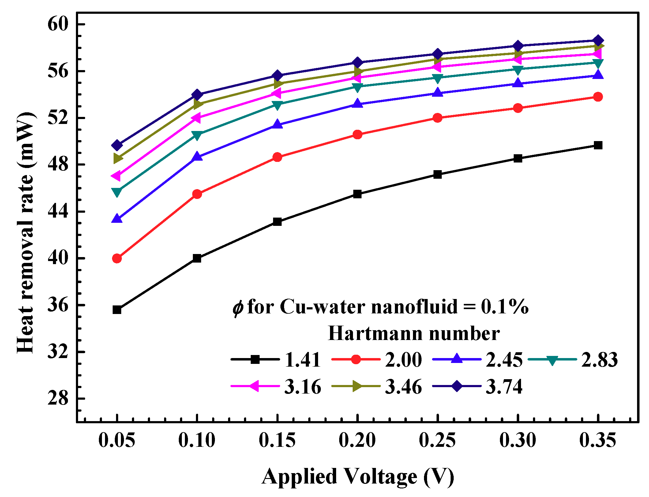
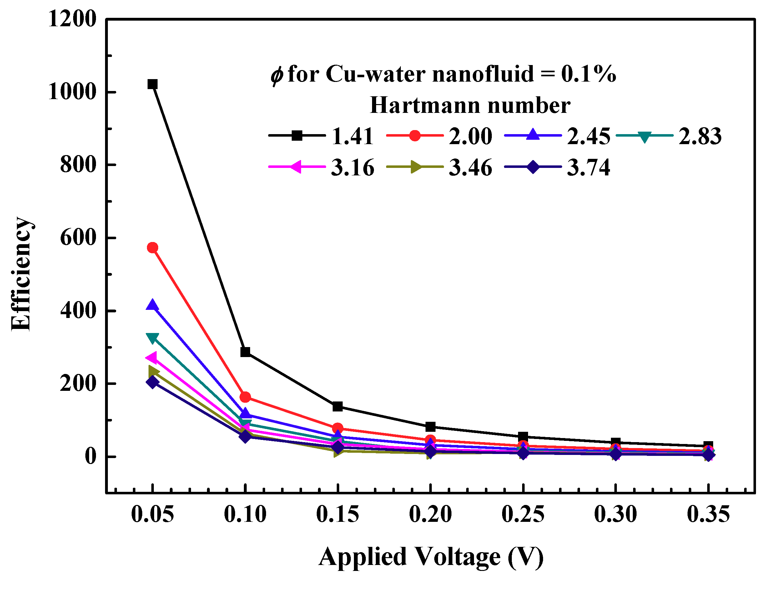
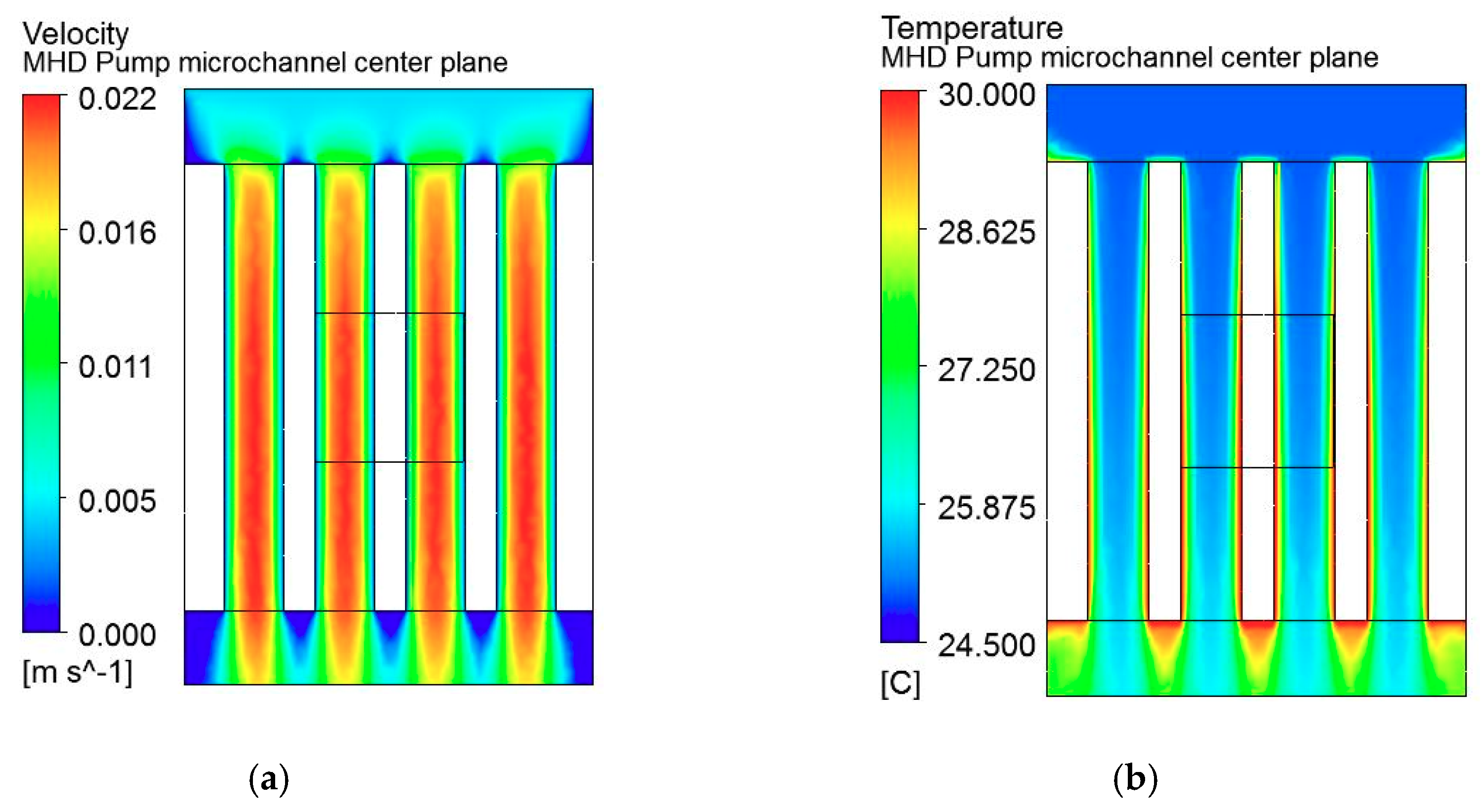
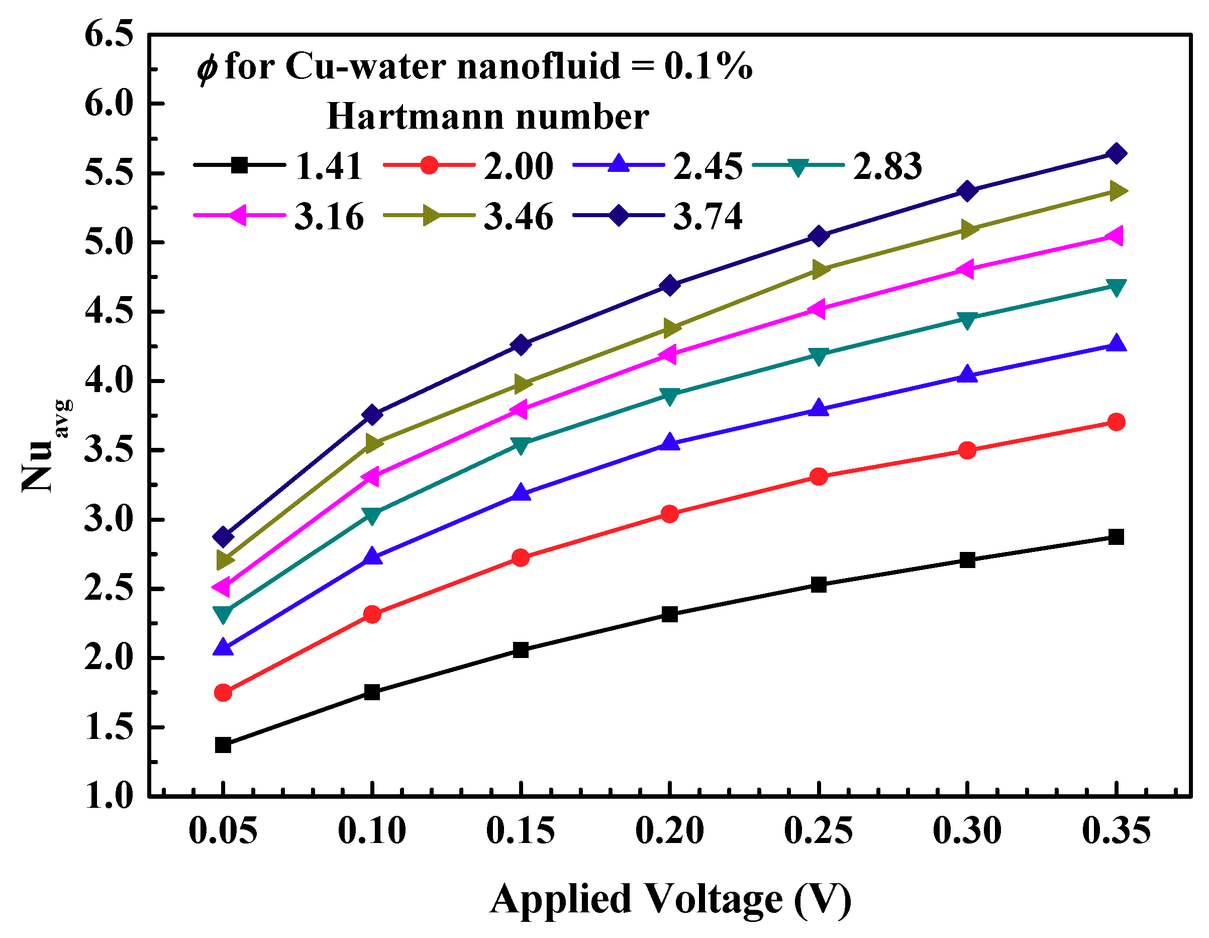
3.3. MHD-Based Microchannel Cooling System

The magnetohydrodynamic pump has various advantages over traditional pumps including low cost, low electric field and no moving parts. The Lorentz force developed by the interaction between the electric current and magnetic field can be used to propel, stir or manipulate the flow behavior in the channel. This section provided the details of the MHD micropump performance considering the applied voltage and Hartmann number.
Figure 11 shows the variation of the maximum temperature of the heat dissipating element for the varied applied voltage and Hartmann number with Cu-water with volume fraction of 0.1% as coolant. As the applied voltage is increased, the maximum temperature of the heat dissipating element decreased. For example, as the applied voltage increased from 0.05 V to 0.35 V at a Hartmann number value of 2.0, the maximum temperature of the heat dissipating element decreased by 7.7%. For the same applied voltage, lower maximum temperatures of the heat dissipating element are observed for a higher Hartmann number. As the Hartmann number increased from 1.41 to 3.76 at a constant applied voltage of 0.05 V, the maximum temperature of the heat dissipating element decreased by 11.0%. The combined influence of higher applied voltage and higher Hartmann number are visible with significant decrease in the maximum temperature of the heat dissipating element. These findings show that the applied voltage and Hartmann number have a significant effect on maintaining and controlling the maximum temperature of the heat dissipating element.
Figure 12 shows variation of the heat removal rate for the varied applied voltage and Hartmann number with Cu-water with the volume fraction of 0.1% as coolant. As the applied voltage is increased, the heat removal rate increased. For example, as the applied voltage increased from 0.05 V to 0.35 V at a Hartmann number value of 2.0, the heat removal rate increased by 34.5%. For the same applied voltage, higher heat removal rates are observed for a higher Hartmann number. As the Hartmann number increased from 1.41 to 3.76 at a constant applied voltage of 0.05 V, the heat removal rate increased by 39.5%. The combined influence of a higher applied voltage and higher Hartmann number are visible with significant increase in heat removal rate. The increase in heat removal rate with a higher applied voltage is attributed to an increase in the volumetric Lorentz force as shown in Figure 7, which subsequently results in the higher volumetric flow rate. It can be seen that for a lower Hartmann number, the rate of change heat removal rate is large, whereas for a higher Hartmann number, the rate of change of heat removal rate is small. This is because the dominance of the magnetic force increased as the Hartmann number increased [10].
Figure 13 shows the variation of efficiency for the varied applied voltage and Hartmann number with Cu-water with volume fraction of 0.1% as coolant. The efficiency is defined as shown in Equation (19).
Efficiency = Heat   removal   rate Input   power
As shown, the efficiency decreased continuously with increase in applied voltage. This shows that, even though for higher applied voltage the heat removal rate is higher, and the temperature of the heat dissipating element is minimum, the heat removal process is less efficient. Therefore, an optimum operating range considering the heat removal rate, temperature of heat dissipating element and efficiency could be considered. As the applied voltage increased from 0.05 to 0.35 V at a Hartmann number value of 3.46, the efficiency decreased from 204.4 to 4.9. For the same applied voltage, a lower efficiency is observed for a higher Hartmann number. As the Hartmann number increased from 1.41 to 3.76 at a constant applied voltage of 0.35 V, the efficiency decreased from 29.1 to 4.9. The combined influence of the higher applied voltage and higher Hartmann number are visible with a significant decrease in efficiency. These findings show that the applied voltage and Hartmann number have a significant effect on efficiency.
Figure 14 shows the velocity and temperature distribution in the MHD pump microchannel cooling system with Cu-water with volume fraction of 0.1% as coolant. As shown in Figure 14a, the velocity is uniformly distributed in the microchannel throughout, which makes it an attractive method for the cooling heat dissipating element, especially where space and noise are constraints such as electronic devices. The rate of increase of the developed flow velocity in the magnetohydrodynamic pump cooling system is an indication of cooling performance as a higher velocity development leads to higher cooling performance. However, the increase in flow velocity has limitations owing to applied voltage and applied magnetic field. As expected, the flow velocity in the thin microchannel increased as it passed through the narrow duct of microchannel cooling system [6]. This is desirable as the heat dissipating element is placed exactly at the center of the microchannel. As shown in Figure 14b, the temperature of the coolant increased as it passed through microchannel. In the present study, the square microchannel design is investigated considering the manufacturing simplicity of the square duct. The future scope of the study involves the use of different shapes of microchannel including circular and trapezoidal. The temperature field distribution for the MHD pump microchannel at the center plane showed that heat transfer occurred along the edges of the microchannel and heat is taken away as the flow proceeded [48]. The geometry based microchannel optimization for effective thermal performance could be carried out considering the requirement of cooling performance and these findings can be used to design an effective cooling by optimizing influencing parameters.
Figure 15 shows the variation of the average Nusselt number for the applied voltage and Hartmann number with Cu-water with a volume fraction of 0.1% as the coolant. The Nusselt number is an indication of enhanced heat transfer due to convection as compared to conduction [49]. The higher Nusselt number indicates the effectiveness of magnetohydrodynamic cooling systems for the heat dissipating element. The average Nusselt number increased with the applied voltage. For example, as the applied voltage increased from 0.05 V to 0.35 V at a Hartmann number value of 2.0, the average Nusselt number increased by 112.6%. For the same applied voltage, a higher average Nusselt number is observed for higher Hartmann numbers. As the Hartmann number increased from 1.41 to 3.76 at a constant applied voltage of 0.25 V, the heat removal rate increased by 100.0%. The combined influence of a higher applied voltage and higher Hartmann number are visible with a significant increase in the average Nusselt number. However, the rate of increase of the average Nusselt number decreased as the applied voltage and Hartmann number increased. The heat transfer performance slightly deteriorated as the value of the Hartmann number increased due to suppression of convection due to the magnetic field [10,50]. These findings show that the applied voltage and Hartmann number have a significant effect on the heat transfer performance of MHD micropumps.

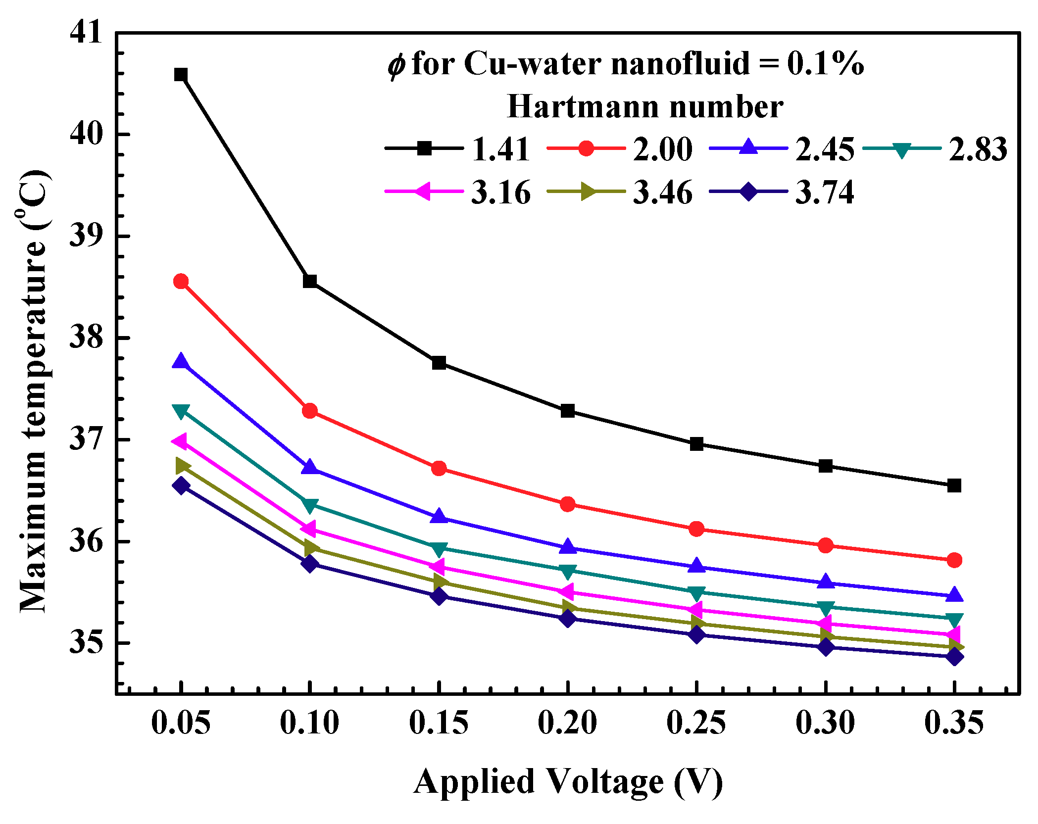
3.4. Influence of Various Nanofluids

The thermal performance of the MHD pump is compared using various nanofluids. Three types of nanofluids including Cu-water, TiO2-water and Al2O3-water are considered with a volume fraction of 0.1%. For performance comparison, the volume fraction of nanoparticles in nanofluids is kept constant. To evaluate the thermal performance of MHD pumps with various nanofluids, the heat transfer rate, efficiency and Nusselt number variation are considered.
Figure 16 shows variation of the heat removal rate for the varied Hartmann number. As the Hartmann number is increased, the heat removal rate increased. For example, as the Hartmann number increased from 1.41 to 3.74 at an applied voltage value of 0.35 V, the heat removal rate increased by 18.0% for Cu-water nanofluids. For the same applied voltage, higher heat removal rates are observed for Cu-water nanofluid as compared to TiO2-water and Al2O3-water nanofluids. As previously noted, for a lower Hartmann number, the rate of change heat removal rate is large, whereas for higher Hartmann number, the rate of change of heat removal rate is small. The Cu-based nanofluid showed a better heat transfer rate owing to the high thermal conductivity of copper nanoparticles.
Figure 17 shows variation of the efficiency for the varied Hartmann number. As the Hartmann number is increased, the efficiency decreased. For example, as the Hartmann number increased from 1.41 to 3.74 at applied voltage value of 0.35 V, efficiency decreased from 29.16% to 4.92% for Cu-water nanofluid. For the same applied voltage, higher efficiencies are observed for Cu-water nanofluid as compared to TiO2-water and Al2O3-water nanofluids. For lower Hartmann number, the rate of change efficiency is large, whereas for higher Hartmann number, the rate of change of efficiency is small. This is because the dominance of magnetic force increased as the Hartmann number increased. The Cu-based nanofluid shows better efficiency owing to high thermal conductivity of copper nanoparticles.
Figure 18 shows variation of the average Nusselt number for the varied Hartmann number. As the Hartmann number is increased, the average Nusselt number increased. For example, as the Hartmann number increased from 1.41 to 3.74 at an applied voltage value of 0.35 V, the average Nusselt number increased by 96.5% for Cu-water nanofluid. For the same applied voltage, higher average Nusselt numbers are observed for Cu-water nanofluid as compared to TiO2-water and Al2O3-water nanofluids. Interestingly, the Nusselt number for the TiO2 based nanofluid and Al2O3 based nanofluid are found to be close. The Cu-based nanofluid showed a better average Nusselt number owing to the high thermal conductivity of copper nanoparticles.

4. Conclusions

Magnetohydrodynamic pump-based microchannel cooling is proposed for cooling heat dissipating elements. The proposed magnetohydrodynamic pump has many advantages including vibration-free and noise-free applications. In the present study, the applied voltage and Hartmann number are varied to evaluate the effect on the MHD pump performance considering normal current density, magnetic flux density, volumetric Lorentz force, shear stress and pump flow velocity as evaluating parameters. The MHD pump-based microchannel cooling system performance with Cu-water nanofluid is evaluated considering the maximum temperature of the heat dissipating element, heat removal rate, efficiency, thermal field, flow field and Nusselt number for various applied voltages and Hartmann numbers. It is found that for a low Hartmann number, the Lorentz force increased with an increase in the applied voltage and Hartmann number. As the applied voltage increased from 0.05 V to 0.35 V at a Hartmann number of 1.41, the heat removal rate increased by 39.5%. The results revealed that for a low Hartmann number, the average Nusselt number increased with increase in the applied voltage and Hartmann number. As the applied voltage increased from 0.05 V to 0.35 V at a Hartmann number of 1.41, the average Nusselt number increased by 112.6%. In addition, the influence of various nanofluids including Cu-water, TiO2-water and Al2O3-water nanofluids on heat transfer performance of MHD pump-based microchannels is evaluated. At the Hartmann number value of 3.74 and applied voltage value of 0.35 V, average Nusselt numbers are 12.3% and 15.1% higher for Cu-water nanofluid compared to TiO2-water and Al2O3-water nanofluids, respectively. The MHD pump is more useful in cases where space and noise constraint are of particular interest. Especially in the microelectronics device cooling, the removal of heat is important and due to miniaturization, the MHD pump for cooling provides a promising option. The investigations provide an opportunity to further explore the application of MHD pumps in electronics cooling.

Author Contributions

Conceptualization, J.-H.S.; M.S.P. and M.-Y.L.; methodology, J.-H.S.; software, M.S.P.; validation, J.-H.S. and M.S.P.; Numerical investigation, J.-H.S. and M.S.P.; resources, M.-Y.L. and S.P.; data reduction, M.S.P. and S.P.; writing—original draft preparation, J.-H.S. and M.S.P.; writing—review and editing, M.-Y.L., and S.P.; visualization, M.S.P.; supervision, M.-Y.L.; project administration, M.-Y.L.; funding acquisition, M.-Y.L. All authors have read and agreed to the published version of the manuscript.

Funding

This research received no external funding.

Acknowledgments

This work was supported by the Dong-A University research fund.

Conflicts of Interest

The authors declare no conflict of interest.

Nomenclature

Across-sectional area (m2)
B magnetic field vector (T)
Bmagnitude of the magnetic field (T)
Cpspecific heat at constant pressure (J/kg-K)
Dhhydraulic diameter (m)
E electric field vector (V/m)
F electromagnetic force (N)
havgaverage heat transfer coefficient (W/m2-K)
HaHartmann number
J current density (A/m2)
Lcharacteristic length (mm)
MHDmagnetohydrodynamic
Nu avg average Nusselt number
Ppressure (Pa)
Qheat transfer rate (W)
Ttemperature (°C/K)
ttime (s)
V velocity (m/s)
Greek symbols
gradient operator
αthermal diffusivity (m2/s)
σelectrical conductivity (S/m)
ρdensity (kg/m3)
νkinematic fluid viscosity (m2/s)
μdynamic viscosity (Pa-s)
kthermal conductivity (W/m-K)
ϕ volume fraction (%)
Subscripts
avgaverage
bulkbulk property
convconvective heat transfer
ffluid
ininlet
LMTDlogarithmic mean temperature difference
nnanoparticle
nfnanofluid
outoutlet
wallwall

References

  1. Al-Habahbeh, O.M.; Al-Saqqa, M.; Safi, M.; Abo Khater, T. Review of magnetohydrodynamic pump applications. Alexandria Eng. J. 2016, 55, 1347–1358. [Google Scholar] [CrossRef] [Green Version]
  2. Derakhshan, S.; Rezaee, M.; Sarrafha, H. A Molecular Dynamics Study of Description Models for Shear Viscosity in Nanochannels: Mixtures and Effect of Temperature. Nanoscale Microscale Thermophys. Eng. 2015, 19, 206–220. [Google Scholar] [CrossRef]
  3. Derakhshan, S.; Adibi, I.; Sarrafha, H. Numerical study of electroosmotic micropump using Lattice Boltzmann method. Comput. Fluids 2015, 114, 232–241. [Google Scholar] [CrossRef]
  4. Tay, F.E.H. Literature Review for Micropumps; Springer: Boston, MA, USA, 2002; pp. 3–24. [Google Scholar]
  5. Zhang, X.; Jaluria, Y. Optimization of microchannel-based cooling systems. Numer. Heat Transf. Part A Appl. 2018, 74, 1053–1067. [Google Scholar] [CrossRef]
  6. Patil, M.S.; Seo, J.H.; Panchal, S.; Jee, S.W.; Lee, M.Y. Investigation on thermal performance of water-cooled Li-ion pouch cell and pack at high discharge rate with U-turn type microchannel cold plate. Int. J. Heat Mass Transf. 2020, 155, 119728. [Google Scholar] [CrossRef]
  7. Lemoff, A.V.; Lee, A.P. AC magnetohydrodynamic micropump. Sens. Actuators B Chem. 2000, 63, 178–185. [Google Scholar] [CrossRef]
  8. Rivero, M.; Cuevas, S. Analysis of the slip condition in magnetohydrodynamic (MHD) micropumps. Sens. Actuators B Chem. 2012, 166–167, 884–892. [Google Scholar] [CrossRef]
  9. Zhao, G.; Jian, Y.; Chang, L.; Buren, M. Magnetohydrodynamic flow of generalized Maxwell fluids in a rectangular micropump under an AC electric field. J. Magn. Magn. Mater. 2015, 387, 111–117. [Google Scholar] [CrossRef]
  10. Yousofvand, R.; Derakhshan, S.; Ghasemi, K.; Siavashi, M. MHD transverse mixed convection and entropy generation study of electromagnetic pump including a nanofluid using 3D LBM simulation. Int. J. Mech. Sci. 2017, 133, 73–90. [Google Scholar] [CrossRef]
  11. Moghaddam, S. Analytical solution of MHD micropump with circular channel. Int. J. Appl. Electromagn. Mech. 2012. [Google Scholar] [CrossRef]
  12. Miroshnichenko, I.V.; Sheremet, M.A.; Oztop, H.F.; Al-Salem, K. MHD natural convection in a partially open trapezoidal cavity filled with a nanofluid. Int. J. Mech. Sci. 2016, 119, 294–302. [Google Scholar] [CrossRef]
  13. Kefayati, G.H.R. Simulation of double diffusive MHD (magnetohydrodynamic) natural convection and entropy generation in an open cavity filled with power-law fluids in the presence of Soret and Dufour effects (Part I: Study of fluid flow, heat and mass transfer). Energy 2016, 107, 889–916. [Google Scholar] [CrossRef]
  14. Kefayati, G.H.R. Simulation of double diffusive MHD (magnetohydrodynamic) natural convection and entropy generation in an open cavity filled with power-law fluids in the presence of Soret and Dufour effects (part II: Entropy generation). Energy 2016, 107, 917–959. [Google Scholar] [CrossRef]
  15. Shirvan, K.M.; Öztop, H.F.; Al-Salem, K. Mixed magnetohydrodynamic convection in a Cu-water-nanofluid-filled ventilated square cavity using the Taguchi method: A numerical investigation and optimization. Eur. Phys. J. Plus 2017, 132, 204. [Google Scholar] [CrossRef]
  16. Kiyasatfar, M.; Pourmahmoud, N.; Golzan, M.; Mirzaee, I. Investigation of thermal behavior and fluid motion in direct current magnetohydrodynamic pumps. Therm. Sci. 2014. [Google Scholar] [CrossRef]
  17. Larimi, M.M.; Ghanaat, A.; Ramiar, A.; Ranjbar, A.A. Forced convection heat transfer in a channel under the influence of various non-uniform transverse magnetic field arrangements. Int. J. Mech. Sci. 2016, 118, 101–112. [Google Scholar] [CrossRef]
  18. Kolsi, L.; Alrashed, A.A.A.A.; Al-Salem, K.; Oztop, H.F.; Borjini, M.N. Control of natural convection via inclined plate of CNT-water nanofluid in an open sided cubical enclosure under magnetic field. Int. J. Heat Mass Transf. 2017, 111, 1007–1018. [Google Scholar] [CrossRef]
  19. Kefayati, G.H.R. FDLBM simulation of magnetic field effect on natural convection of non-Newtonian power-law fluids in a linearly heated cavity. Powder Technol. 2014, 256, 87–99. [Google Scholar] [CrossRef]
  20. Kefayati, G.H.R. Simulation of magnetic field effect on non-Newtonian blood flow between two-square concentric duct annuli using FDLBM. J. Taiwan Inst. Chem. Eng. 2014, 45, 1184–1196. [Google Scholar] [CrossRef]
  21. Kefayati, G.H.R. Simulation of vertical and horizontal magnetic fields effects on non-Newtonian power-law fluids in an internal flow using FDLBM. Comput. Fluids 2015, 114, 12–25. [Google Scholar] [CrossRef]
  22. Sheikholeslami, M.; Ganji, D.D. Ferrohydrodynamic and magnetohydrodynamic effects on ferrofluid flow and convective heat transfer. Energy 2014, 75, 400–410. [Google Scholar] [CrossRef]
  23. Sheikholeslami, M.; Gorji-Bandpy, M.; Ganji, D.D. Numerical investigation of MHD effects on Al2O3-water nanofluid flow and heat transfer in a semi-annulus enclosure using LBM. Energy 2013, 60, 501–510. [Google Scholar] [CrossRef]
  24. Patil, M.S.; Bang, Y.M.; Seo, J.H.; Kim, D.W.; Cho, B.D.; Lee, M.Y. Experimental investigation of heat transfer characteristics of battery management system and electronic control unit of neighborhood electric vehicle. In Lecture Notes in Electrical Engineering; Springer: Cham, Switzerland, 2017; Volume 415, pp. 205–211. ISBN 9783319509037. [Google Scholar]
  25. Patil, M.S.; Seo, J.; Panchal, S.; Lee, M. Numerical study on sensitivity analysis of factors influencing liquid cooling with double cold-plate for lithium-ion pouch cell. Int. J. Energy Res. 2020, 1–27. [Google Scholar] [CrossRef]
  26. Joye, D.D.; Bushinsky, J.P.; Saylor, P.E. Mixed Convection Heat Transfer at High Grashof Number in a Vertical Tube. Ind. Eng. Chem. Res. 1989, 28, 1899–1903. [Google Scholar] [CrossRef]
  27. Patil, M.S.; Seo, J.H.; Bang, Y.M.; Lee, M.Y. Analysis of factors influencing on heat transfer characteristics of automobile LED headlamp. Int. J. Control Autom. 2016, 9, 263–272. [Google Scholar] [CrossRef]
  28. Patil, M.S.; Seo, J.-H.; Bang, Y.-M.; Lee, M.-Y. Experimental Study on the Performance Characteristics of an Air-Cooled LED Cooling System for Headlamp of a Passenger Vehicle. Adv. Sci. Technol. Lett. 2016, 120, 120–128. [Google Scholar] [CrossRef]
  29. Patil, M.S.; Seo, J.H.; Kim, C.M.; Lee, J.Y.; Lee, M.Y. Numerical study on magneto-acoustic thermal characteristics of micro-speaker for mobile phones. Int. J. Heat Mass Transf. 2021, 164, 120479. [Google Scholar] [CrossRef]
  30. Khan, A.A.; Kim, K.Y. Evaluation of Various Channel Shapes of a Microchannel Heat Sink. Int. J. Air-Cond. Refrig. 2016, 24, 1650018. [Google Scholar] [CrossRef]
  31. Saqib, M.; Shafie, S.; Khan, I.; Chu, Y.M.; Nisar, K.S. Symmetric MHD channel flow of nonlocal fractional model of BTF containing hybrid nanoparticles. Symmetry 2020, 12, 663. [Google Scholar] [CrossRef]
  32. Permanasari, A.A.; Kuncara, S.; Puspitasari, P.; Sukarni, S.; Ginta, T.L.; Irdianto, W. Convective heat transfer characteristics of TiO2-EG nanofluid as coolant fluid in heat exchanger. AIP Conf. Proc. 2019, 2120, 50014. [Google Scholar] [CrossRef]
  33. Abu-Nada, E. Effects of variable viscosity and thermal conductivity of Al2O3-water nanofluid on heat transfer enhancement in natural convection. Int. J. Heat Fluid Flow 2009, 30, 679–690. [Google Scholar] [CrossRef]
  34. Pak, B.C.; Cho, Y.I. Hydrodynamic and heat transfer study of dispersed fluids with submicron metallic oxide particles. Exp. Heat Transf. 1998. [Google Scholar] [CrossRef]
  35. Zhong, D.; Zhong, H.; Wen, T. Investigation on the thermal properties, heat transfer and flow performance of a highly self-dispersion TiO2 nanofluid in a multiport mini channel. Int. Commun. Heat Mass Transf. 2020. [Google Scholar] [CrossRef]
  36. Batchelor, G.K. The effect of Brownian motion on the bulk stress in a suspension of spherical particles. J. Fluid Mech. 1977. [Google Scholar] [CrossRef]
  37. Vand, V. Theory of viscosity of concentrated suspensions. Nature 1945, 155, 364–365. [Google Scholar] [CrossRef]
  38. Wang, X.; Xu, X.; Choi, S.U.S. Thermal conductivity of nanoparticle-fluid mixture. J. Thermophys. Heat Transf. 1999. [Google Scholar] [CrossRef]
  39. Duangthongsuk, W.; Wongwises, S. Measurement of temperature-dependent thermal conductivity and viscosity of TiO2-water nanofluids. Exp. Therm. Fluid Sci. 2009. [Google Scholar] [CrossRef]
  40. Bobbo, S.; Fedele, L.; Benetti, A.; Colla, L.; Fabrizio, M.; Pagura, C.; Barison, S. Viscosity of water based SWCNH and TiO2 nanofluids. Exp. Therm. Fluid Sci. 2012. [Google Scholar] [CrossRef]
  41. Timofeeva, E.V.; Gavrilov, A.N.; McCloskey, J.M.; Tolmachev, Y.V.; Sprunt, S.; Lopatina, L.M.; Selinger, J.V. Thermal conductivity and particle agglomeration in alumina nanofluids: Experiment and theory. Phys. Rev. E Stat. Nonlinear Soft Matter Phys. 2007. [Google Scholar] [CrossRef] [Green Version]
  42. Xuan, Y.; Roetzel, W. Conceptions for heat transfer correlation of nanofluids. Int. J. Heat Mass Transf. 2000. [Google Scholar] [CrossRef]
  43. Hwang, S.; Jeong, J.H. Performance Comparison of Modified Offset Strip Fins Using a CFD Analysis. Int. J. Air-Conditioning Refrig. 2016, 24, 1650015. [Google Scholar] [CrossRef]
  44. Aoki, L.P.; Schulz, H.E.; Maunsell, M.G. An MHD Study of the Behavior of an Electrolyte Solution using3D Numerical Simulation and Experimental results. In Proceedings of the COMSOL Conference, Boston, MA, USA, 14 October 2013. [Google Scholar]
  45. Kandev, N.; Kagan, V.; Daoud, A. Electromagnetic DC pump of liquid aluminium: Computer simulation and experimental study. Fluid Dyn. Mater. Process. 2010. [Google Scholar] [CrossRef]
  46. Zakeri, R.; Sabouri, M.; Maleki, A.; Abdelmalek, Z. Investigation of Magneto Hydro-Dynamics Effects on a Polymer Chain Transfer in Micro-Channel Using Dissipative Particle Dynamics Method. Symmetry 2020, 12, 397. [Google Scholar] [CrossRef] [Green Version]
  47. Daoud, A.; Kandev, N. Magneto-hydrodynamic numerical study of DC electromagnetic pump for liquid metal. In Proceedings of the COMSOL Conference, Hannover, Germany, 5 November 2008. [Google Scholar]
  48. Ekanayake, G.; Patil, M.S.; Seo, J.-H.; Lee, M.-Y. Numerical study of fin geometry on the heat transfer characteristics of 72 V ECU heatsink for an electric three-wheeler. J. Mech. Sci. Technol. 2019, 33, 1451–1462. [Google Scholar] [CrossRef]
  49. Seo, J.H.; Patil, M.S.; Cho, C.P.; Lee, M.Y. Heat transfer characteristics of the integrated heating system for cabin and battery of an electric vehicle under cold weather conditions. Int. J. Heat Mass Transf. 2018. [Google Scholar] [CrossRef]
  50. Selimefendigil, F.; Öztop, H.F. Analysis of MHD mixed convection in a flexible walled and nanofluids filled lid-driven cavity with volumetric heat generation. Int. J. Mech. Sci. 2016, 118, 113–124. [Google Scholar] [CrossRef]
Figure 1. Schematic view of the magnetohydrodynamic (MHD) pump microchannel cooling system for a heat dissipating element.
Symmetry 12 01713 g001
Figure 2. Effect of nanoparticle volume fraction on the mixture properties.
Symmetry 12 01713 g002
Figure 3. Mesh details (a) Mesh independency test (b) Meshing of magnetohydrodynamic (MHD) pump microchannel cooling system for heat dissipating element.
Symmetry 12 01713 g003
Figure 4. Velocity comparison between present study and the Lemoff et al. [7] experimental study and Yousofvand et al. [10] numerical study.
Symmetry 12 01713 g004
Figure 5. Current density and velocity (a) Normal current density variation for different applied voltage and different Hartmann number (b) Induced current density distribution (c) Variation of average velocity with current density.
Symmetry 12 01713 g005aSymmetry 12 01713 g005b
Figure 6. Magnetic flux density and magnetic field (a) Magnetic flux density variation with dimensionless width for different applied voltages and different Hartmann number (b) Magnetic field distribution at the center of the MHD pump in the XY-plane.
Symmetry 12 01713 g006
Figure 7. Volumetric Lorentz force variation for different applied voltages and different Hartmann number.
Symmetry 12 01713 g007
Figure 8. Shear stress and Pressure (a) Shear stress variation with dimensionless width for different applied voltages and different Hartmann numbers (b) Pressure contours for the flow cross-sectional area at the center of the pump in the YZ-plane
Symmetry 12 01713 g008
Figure 9. Velocity variation with dimensionless width.
Symmetry 12 01713 g009
Figure 10. Velocity variation with dimensionless width.
Symmetry 12 01713 g010
Figure 11. Maximum temperature.
Symmetry 12 01713 g011
Figure 12. Heat removal rate variation.
Symmetry 12 01713 g012
Figure 13. Variation of efficiency with applied voltage.
Symmetry 12 01713 g013
Figure 14. Velocity and temperature distribution in MHD pump microchannel cooling system.
Symmetry 12 01713 g014
Figure 15. Variation of average Nusselt number with applied voltage.
Symmetry 12 01713 g015
Figure 16. Variation of heat removal rate with various nanofluids at different Hartmann numbers.
Symmetry 12 01713 g016
Figure 17. Variation of efficiency with various nanofluids at different Hartmann numbers.
Symmetry 12 01713 g017
Figure 18. Variation of average Nusselt number with various nanofluids at different Hartmann numbers.
Symmetry 12 01713 g018
Table 1. MHD pump and microchannel dimensions.
ItemParameterValues
MHD pumpLength × Height (mm)80 × 10
MicrochannelLength × Width × Height (mm)30 × 30 × 10
Number of channel slots (ea)4
Single channelWidth × Height (mm)4 × 7
Magnet radiusRadius × Height (mm)15 × 7.5
Heat dissipating elementLength × Width × Height (mm)10 × 10 × 1
Table 2. Boundary conditions and thermophysical properties.
SpecificationsValues
Boundary conditions
Inlet coolant temperature (°C)25
Applied Voltage (V)0.05, 0.10, 0.15, 0.20, 0.25, 0.30, 0.35
Volumetric heat generation rate (W/m3)1.0 × 108
Coolant inletOpening at atmospheric pressure
Coolant outletOpening at atmospheric pressure
Thermophysical properties
WaterCuTiO2 [32]Al2O3 [33]
Density (kg/m3)997895442603970
Thermal conductivity (W/m-K)0.60694008.925
Specific heat (J/kg-K)4181.7383686.2765
Table 3. Mesh details.
Mesh TypeNumber of Elements
Type 15.43 × 10⁴
Type 21.56 × 10⁵
Type 36.09 × 10⁵
Type 49.65 × 10⁵
Type 51.45 × 10⁶
Publisher’s Note: MDPI stays neutral with regard to jurisdictional claims in published maps and institutional affiliations.

