Article

Analysis of Acoustic Emission Characteristics and Damage Constitutive Model of Coal-Rock Combined Body Based on Particle Flow Code

1
School of Physics Science and Information Technology, Liaocheng University, Liaocheng 252059, China
2
School of Civil Engineering, Southeast University, Nanjing 210096, China
*
Author to whom correspondence should be addressed.
Symmetry 2019, 11(8), 1040; https://doi.org/10.3390/sym11081040
Submission received: 14 July 2019 / Revised: 29 July 2019 / Accepted: 7 August 2019 / Published: 13 August 2019

Abstract

:
In this manuscript, the numerical coal-rock combined bodies with different height ratios of rock part to coal-rock combined body (HRRC) were established by particle flow code (PFC) firstly, and then the influence of different HRRC on mechanical properties and numerical acoustic emission (AE) characteristics of coal-rock combined bodies were investigated. Finally, the damage constitutive model of the coal-rock combined body was discussed. The research results show that with the increase of the HRRC, the UCS and the elastic modulus (E) of the combined coal-rock bodies increased. The failure of coal-rock combined bodies is mainly focused on the coal body. The evolution law of AE hits of coal-rock combined bodies have three stages, named stable stage, rapid ascending stage, and rapid descending stage. The damage variable curves of coal-rock combined body have two stages, named slowly damage stage and sharply damage stage. The damage constitutive relation based on AE hits can well reflect the stress-strain relationships with a lower HRRC. However, for a higher HRRC, the damage constitutive equation is not accurately and the damage of the rock part in the coal-rock-combined body should be considered.

1. Introduction

With the increase of mining scale and intensity, rock bursts, coal-gas outburst, and other coal mine disasters are becoming more common [1,2,3,4]. According to statistics [5], from 2004 to 2016, a total of 20,980 coal mine accidents occurred in China, and most of them were caused by the damage of coal pillars. Coal pillar is a part of the coal-rock mass system, and its failure and instability is the result of the interaction of coal and rock mass, and is a weakening process of gradual development [6]. Therefore, it is of great engineering significance to study the mechanical characteristics and damage mechanism of coal-rock combined bodies to prevent the instability of coal pillars.
Many scholars have carried out a lot of research work on coal-rock combined bodies and obtained many interesting results. For example, Newman [7] found that the designed coal pillar has the potential for lateral expansion, and the friction along the interface between top and floor rock and coal is very important for rock burst. Liu et al. [8] carried out numerical simulations on the coal-rock series combination model and the results show that the combined coal-rock sample can reflect the basic mechanical phenomena in the process of rock burst. Li et al. [9] studied the impact tendency of single coal sample and coal-rock combination, and the results show that the impact tendency index of coal-rock combination is higher than that of the single coal sample. Zuo et al. [10] investigated the deformation and failure behavior of a rock-coal-rock combined body containing a weak coal inter-layer under different confining pressures and found that with increasing confining pressure, the failure strength of a rock-coal-rock combined body gradually increases, and the failure mechanism of the coal interlayer also changes, from mixed crack damage under low confining pressures, to parallel crack damage under medium confining pressures, and finally to single shear crack damage or integral mixed section damage under highly-confining pressures. Guo et al. [11] explored the influence of coal thickness on the mechanical behavior and the failure characteristics of rock-coal-rock (RCR) mass by particle flow code (PFC2D), and the result show that the failure mechanism of RCR specimen is different under different coal thicknesses and confining pressures.
Under the action of external load, cracks will occur in coal and rock mass, and stress waves will be released in the process of crack propagation, that is, the so-called acoustic emission phenomenon. Many scholars monitor the crack propagation in the coal and rock loading process by acoustic emission-charge signal, as an auxiliary means to study the mechanical properties of coal-rock mass [12,13,14,15]. For example, Tan et al. [14] studied the influence of homogeneity on the rock-burst tendency and on AE characteristics of coal-rock combination body, and the result show that the more inhomogeneous the coal-rock combined body is, the shorter the lasting time in the active period of AE characteristics will be. Yin et al. [15] analyzed the effects of joint angle on the acoustic emission characteristics of coal-rock combined body, and the result show that with an increase in the included angle α between the loading direction and joint plane direction, the AE duration time first decreases and then increases.
The above literature studied coal-rock assemblages from the mechanical and acoustic point of view, which is of great significance to the safety and stability control of coal pillars in mines. However, at present, the research on the instability mechanism of coal-rock mass is not enough to completely control mine disasters, and the research on damage evolution law and model of coal-rock combination is less. Therefore, in this manuscript, the numerical coal-rock combined bodies with different height ratios of rock part to coal-rock combined body (HRRC) were established based on PFC firstly, and then the influence of different HRRC on mechanical properties and AE characteristics of coal-rock combined bodies were investigated. Finally, the damage constitutive model of the coal-rock combined body was discussed. The research results are helpful to further control coal and rock disasters in mines.

2. Numerical Model of Combined Coal-Rock by Particle Flow Code

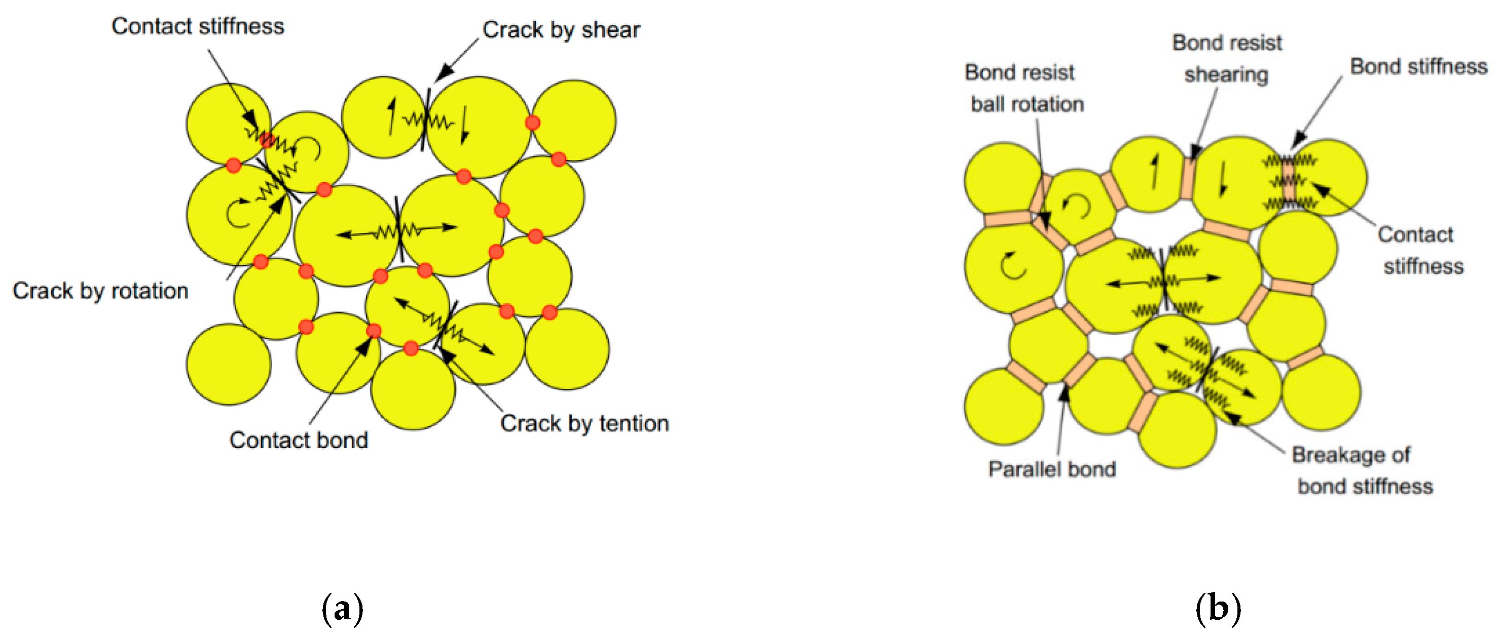
2.1. Particle Flow Code (PFC)

Particle flow code was established based on discrete element method by Cundall and Strack [16] in 1979 and it has been widely used in geotechnical engineering, geological engineering and mining engineering [17,18,19,20,21]. In PFC, the coal, rock, or coal-rock combined mass are characterized by particles and bonds, and there are two bonds, named contact bond (CB) and parallel bond (PB), which can be used to represent the connection between model grains, as shown in Figure 1 [19,20]. The CB model (Figure 1a) is point contact and it cannot resist bending moment. The contact bond model is generally suitable for simulating soil materials. However, the PB model (Figure 1b) can resist bending moment due to the area contact between particles and it is suitable to simulate rock, coal or other solid materials. In this paper, the coal-rock combined bodies were established based on PB models.

2.2. Meso-Mechanical Parameters of Combined Coal-Rock Model

In PFC, the macro-mechanical parameters, such as compressive intensity and elastic modulus, are represented by the meso-parameters, such as particle diameter, contact modulus of particles, the strength and cohesive force of bonds, etc., and theses parameters cannot be directly obtained from experimental data [20]. Therefore, before numerical simulation, PFC meso-parameters need to be adjusted to obtain macro-parameters which are close to the macro-parameters of experimental data. Owing to the limitation of the laboratory test condition, the meso-parameters of numerical rock specimens (Table 1) provided by Zhang et al. [22] and the meso-parameters of numerical coal specimens (Table 2) provided by Wang et al. [23] were used in this paper to simulate coal-rock combined bodies. In their articles, they compared the stress-strain curves and failure modes of real rock specimen and real coal specimen with numerical rock and coal mass, as shown in Figure 2 and Figure 3. It can be seen that the meso-parameters of numerical rock mass and coal mass can represent the macro-mechanical properties of real rock and coal mass approximately, and the parameters listed in Table 1 and Table 2 can be used to simulate the coal-rock combined bodies.

2.3. Numerical Acoustic Emission (AE) Based on Bonds Breakages

Under the action of external load, cracks will occur in coal and rock mass, and stress waves will be released in the process of crack propagation, that is, the so-called acoustic emission phenomenon. Acoustic emission originates from crack propagation in the coal-rock mass and for PFC numerical coal-rock models, the crack propagation is based on “bond breakages”. In the process of compression, the parallel bond will break when the stress intensity transmitted between the particles exceeds the bonding strength between the particles [15,22] and a numerical AE event occurs (an AE hits). Note that the numerical acoustic emission of PFC simulation is different from the acoustic emission monitored by the actual test, but there are similarities, which can reflect the destruction process of the material from a mesoscopic perspective [24,25,26,27]. In this paper, the AE characteristics of different coal-rock combined bodies are analyzed based on the number of AE hits (equal to the number of bonds breakages).

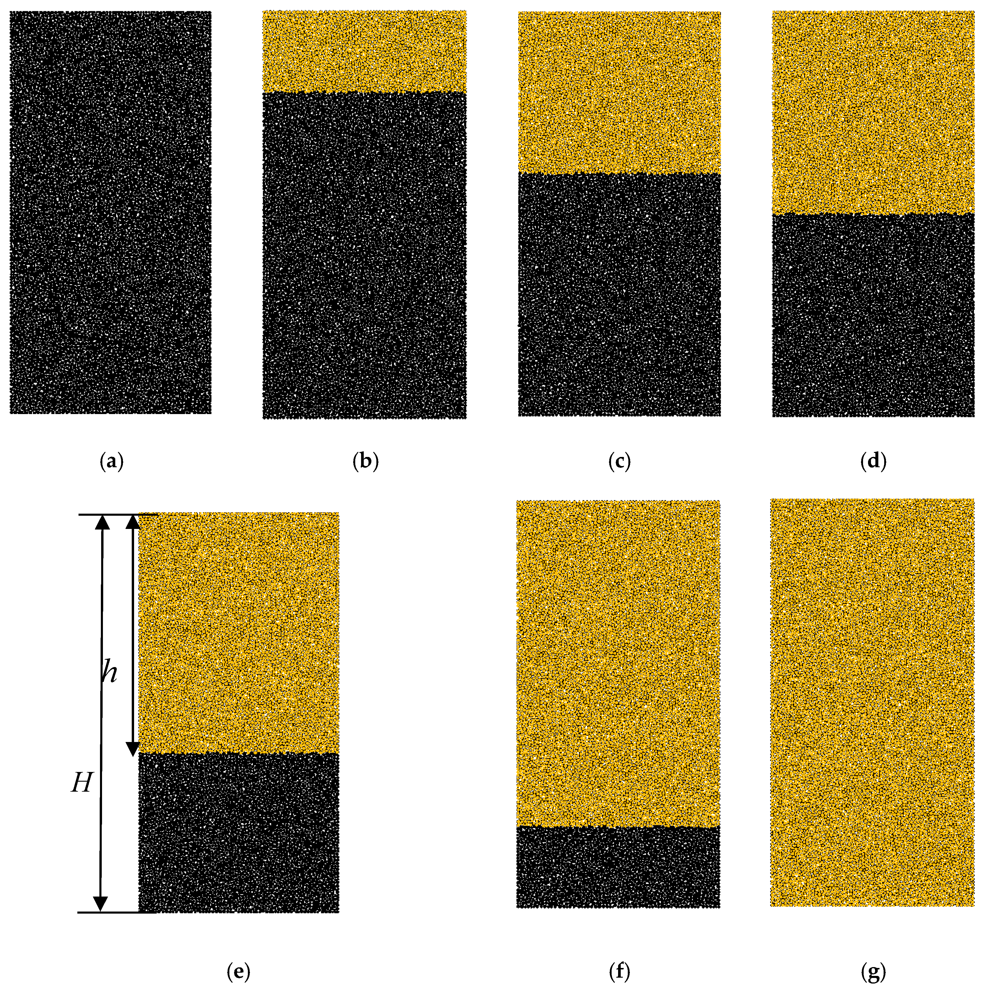
2.4. Numerical Combined Coal-Rock Model

In order to study the mechanical properties, AE characteristics and damage constitutive relation of combined coal-rock, in this paper, seven coal-rock combined models with different HRRC were established, as shown in Figure 4. The HRRC is defined as follow.
H R R C = h r o c k H t o t a l
where, hrock is the height of the rock in the coal-rock combined body, and Htotal is height of the coal-rock combined body.
The HRRC are equal to 0, 0.2, 0.4, 0.5, 0.6, 0.8, and 1.0, respectively. In the tests, the loading is applied by moving the top wall, and the loading rate of all the models is 0.05 m/s.

3. Result Analysis

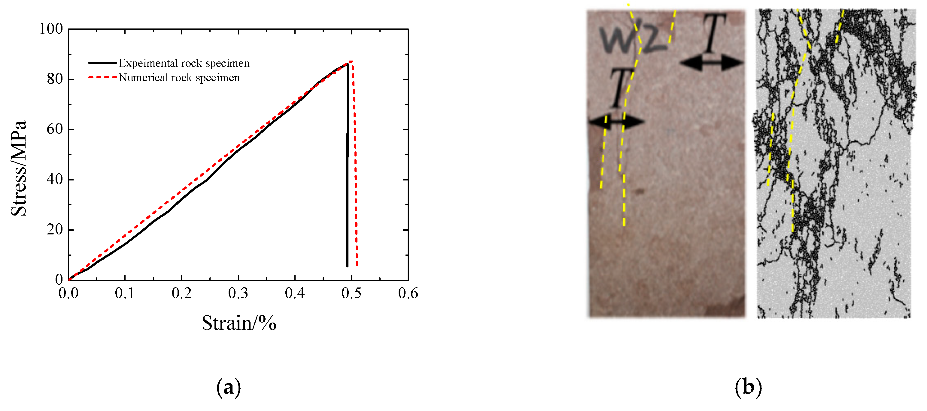
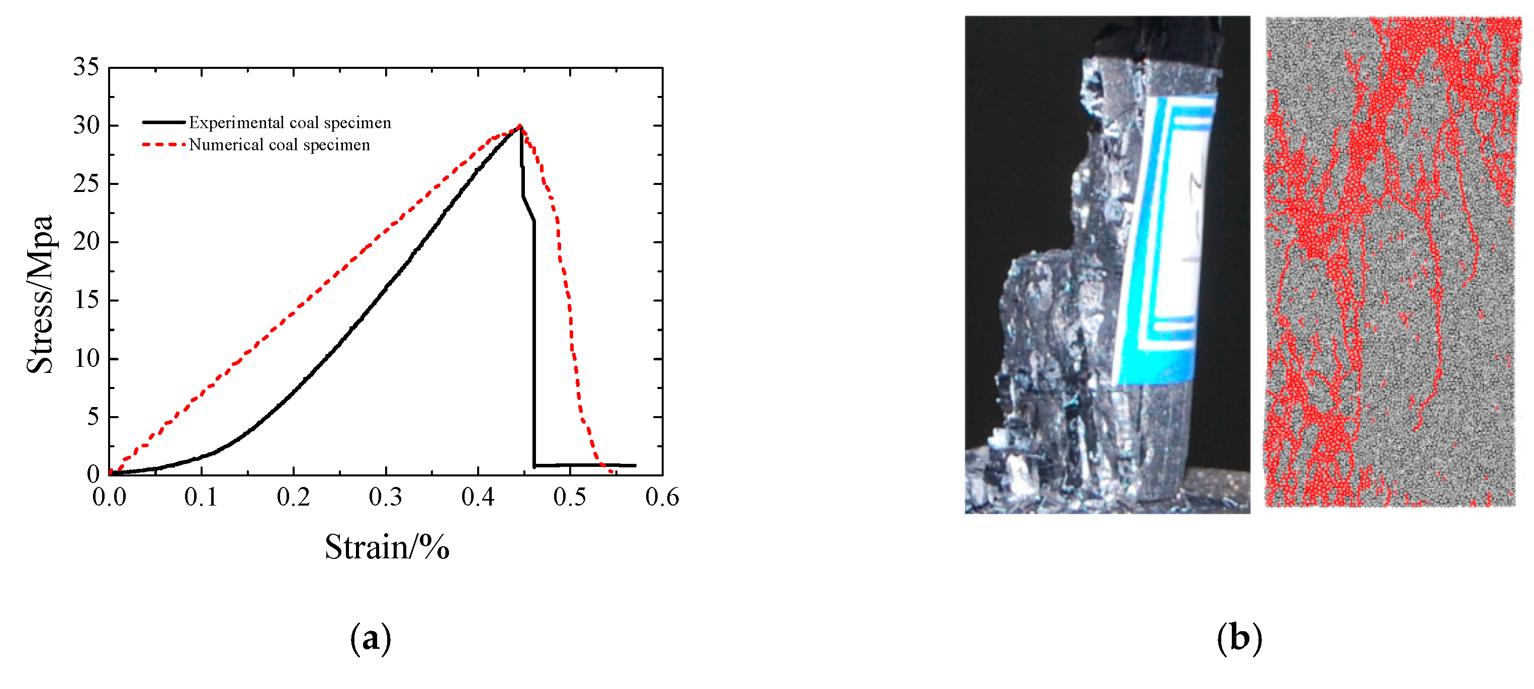
3.1. Mechanical Behavior of Coal-Rock Combined Bodies

Figure 5, Figure 6 and Figure 7 shows the stress-strain curves, uniaxial compressive strength (UCS), and elastic modulus (E) of coal-rock combined bodies with different HRRC. It can be seen that along with the increase of the HRRC, the UCS and the E of the combined coal-rock bodies increase. When the HRRC is equal to 0.0, 0.2, 0.4, 0.5, 0.6, 0.8, and 1.0, the UCSs of the combined coal-rock bodies models are 31.29 MPa, 31.57 MPa, 31.95 MPa, 32.44 MPa, 32.97 MPa, 34.99 MPa, and 80.81 MPa, and the E are 7.87 GPa, 8.91 GPa, 10.03 GPa, 10.08 GPa, 12.26 GPa, 13.76 GPa, and 17.39 GPa, respectively. The difference of UCS between coal-rock combined bodies (HRRC = 0.2, 0.4, 0.5, 0.6, 0.8) and coal specimen is very small, less than 4 MPa, and this shows that the strength of the coal-rock combined bodies is mainly determined by the strength of the coal body. As for E, the increase is gradual with the increase of HRRC, and this illustrates that the influence of HRRC of coal-rock combined bodies on the E is higher than on UCS. These research results are corresponding to the conclusions of Zuo et al. [28]. In addition, from Figure 5, it can be seen that the stress-strain curve will fluctuate several times when near to the UCS with HRRC equal to 0.8. The authors believe that this is related to the failure mode of coal and rock mass, and the possible causes will be discussed in Section 3.2.

3.2. Failure Mode of Coal-Rock Combined Bodies

During the process of compression, the parallel bond will break when the stress intensity transmitted between the particles exceeds the bonding strength between the particles and the aggregation of bond breakages forms the failure mode of coal-rock combined bodies. Figure 8 depicts the failure modes of coal-rock combined bodies with different HRRC. Form the figure, it can be seen that the failure of coal-rock combined bodies mainly focuses on coal body, and this shows that the failure modes of coal-rock combined bodies are mainly controlled by coal body, as the strength characteristics described in Section 3.1. Besides HRRC = 0.0 and 1.0, the failure modes of coal-rock combined bodies are similar, like the “V” shape and the opening of “V” become larger as HRRC increases. The reason is that with the increase of HRRC, the ratio of width to height of coal body becomes larger and larger, and the larger the ratio of width to height, the larger the damage width of coal body. Note that when HRRC = 0.8, the failure parts of rock mass and coal mass expand outward, which is the reason for the peak fluctuation of the stress-strain curve when HRRC = 0.8. When HRRC is equal to 0.0, the failure modes have an inverted “V” or inverted “Y” shape. When HRRC equals to 1.0, the rock mass is inclined to splitting failure.

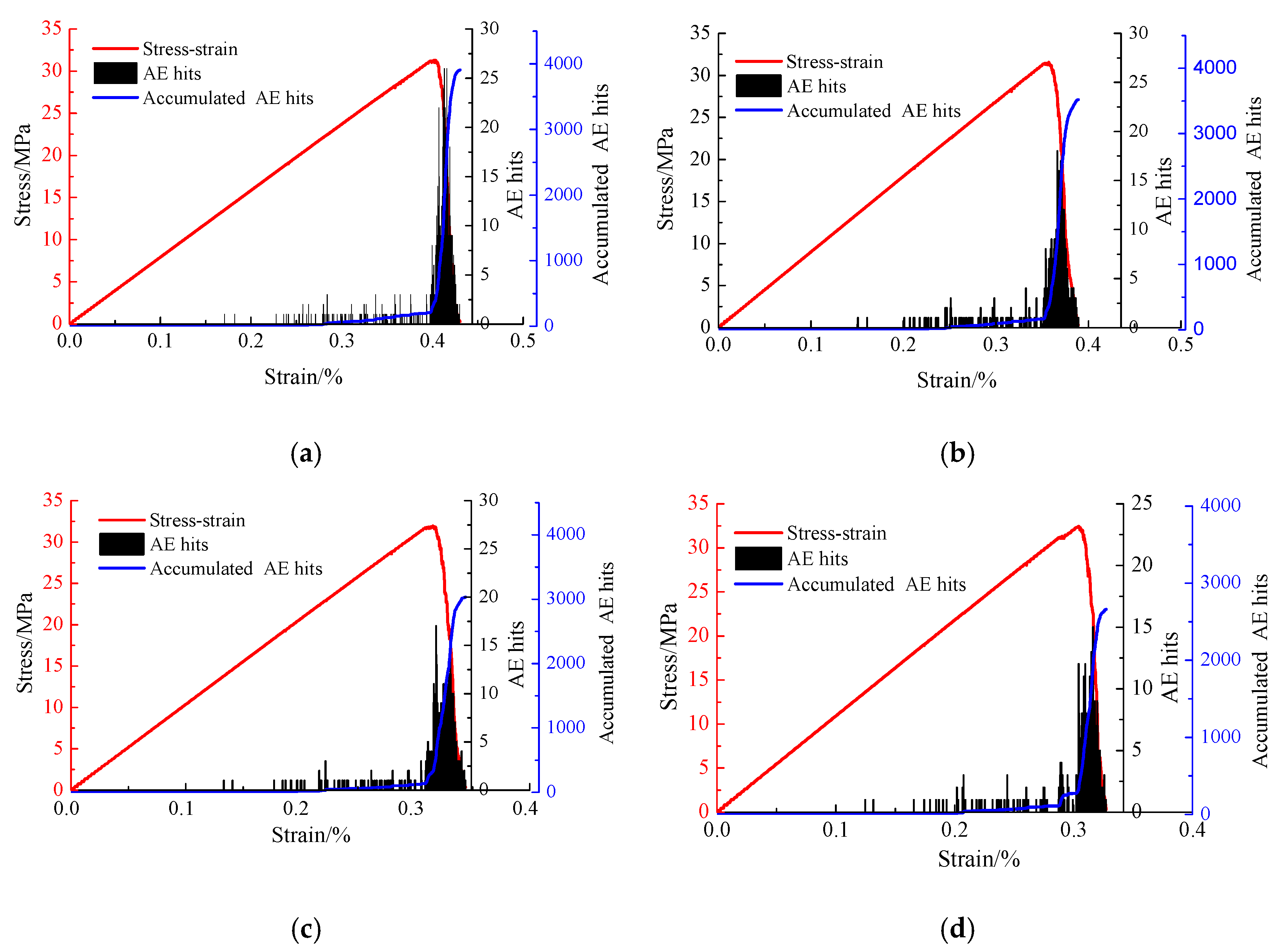
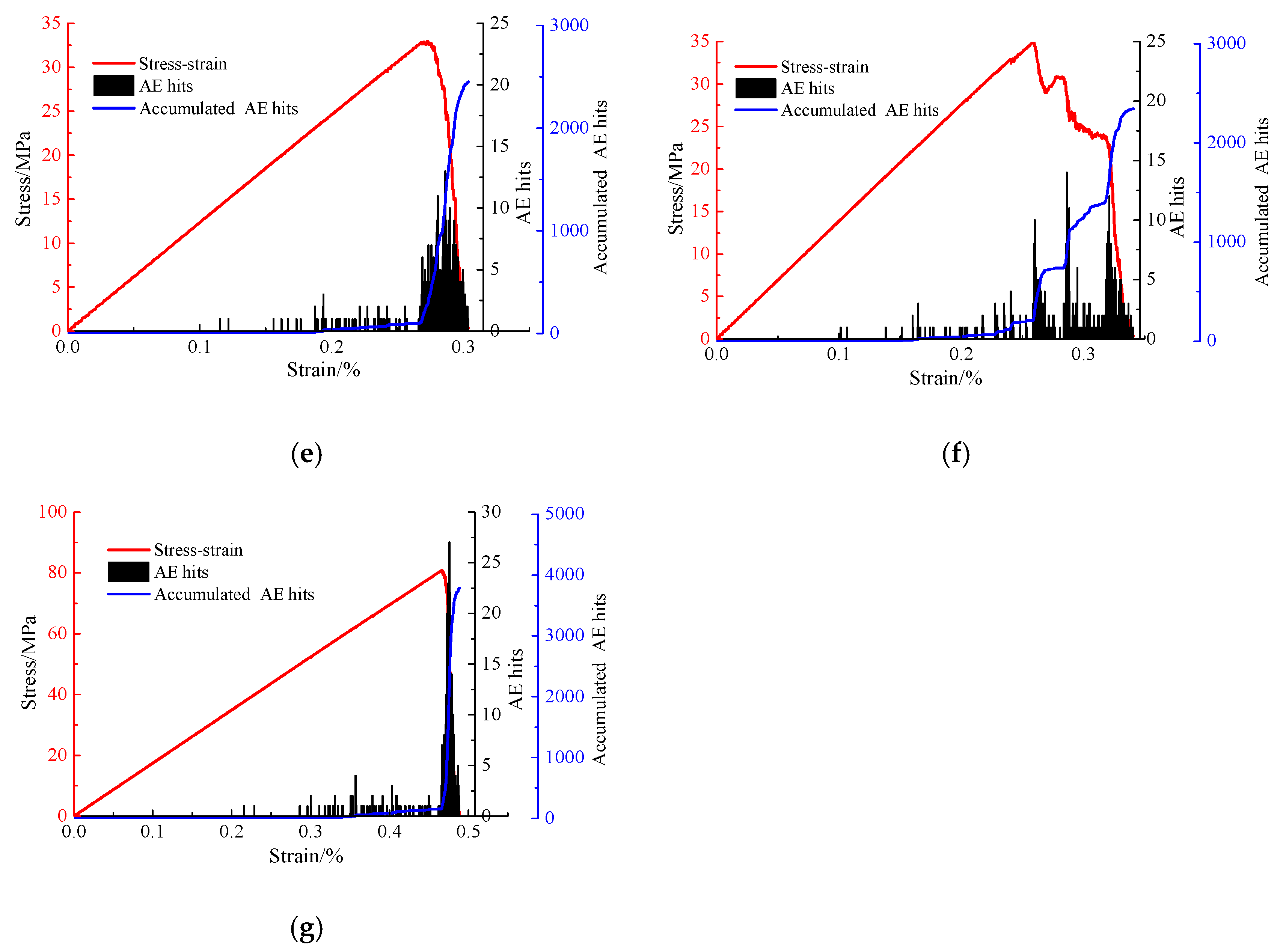
3.3. AE Characteristics of Coal-Rock Combined Bodies

Figure 9 shows the stress-strain-AE hits curves of coal-rock combined bodies with different HRRC. It should be noted that AE hits or the accumulated AE hits come from the breakage of bonds, and the numerical acoustic emission of PFC simulation is different from the acoustic emission monitored by the actual test. Apart from HRRC = 0.8, the evolution law of AE hits of coalrock combined bodies are similar. The evolution law of AE hits of coal-rock combined bodies have three stages, named stable stage, rapid ascending stage, and rapid descending stage. The stable stage of AE hits refers to the breakages of bonds of the combined coal-rock body is slightly and continuously and it mainly occurs before the peak stress of the stress-strain curve; the rapid ascending stage of AE refers to the breakages of bonds of the combined coal-rock body, which rapidly increases, and this stage occurs around the peak stress of the stress-strain curve; while the rapid descending stage of AE refer to the breakages of bonds of the combined coal-rock body, which reaches the max (no or little new damage will occur), and this stage occurs after the peak stress of the stress-strain curve.
The maximum AE hits number of the stress-strain-AE hits curves and the total accumulated AE hits number decrease with the increase of HRRC (except HRRC = 1.0). As the HRRC increases from 0.0 to 1.0, the maximum AE hits numbers of the stress-strain-AE hits curves are 27, 18, 17, 15, 14, and 12, and the total accumulated AE hits numbers are 3907, 3529, 3033, 2669, 2452, and 2346, respectively. The reason is that the higher the HRRC, the higher the UCS of coal-rock combined body and the harder to from cracks, which is where the AE hits originate. When HRRC = 1.0, the maximum AE hits number of the stress-strain-AE hits curve is 29, and the total number of acoustic emission events number is 3790. The reason is that the amount of energy accumulated around the peak stress of the stress-strain curve of coal rock combined body with HRRC equals to 1 is higher than other coal-rock bodies, and the number of bond breakages caused by the release of energy is larger.
As for HRRC = 0.8, the evolution law of AE hits curve and accumulated AE hits curve is different from the others, and they fluctuate with the fluctuation of the stress-strain curve. The reason also comes from the failure modes of this coal-rock combined body (the failure of the rock part in the coal-rock combined body). In addition, this phenomenon illustrated that the AE hits have an interior relation with the stress, strain and damage of coal-rock combined bodies.

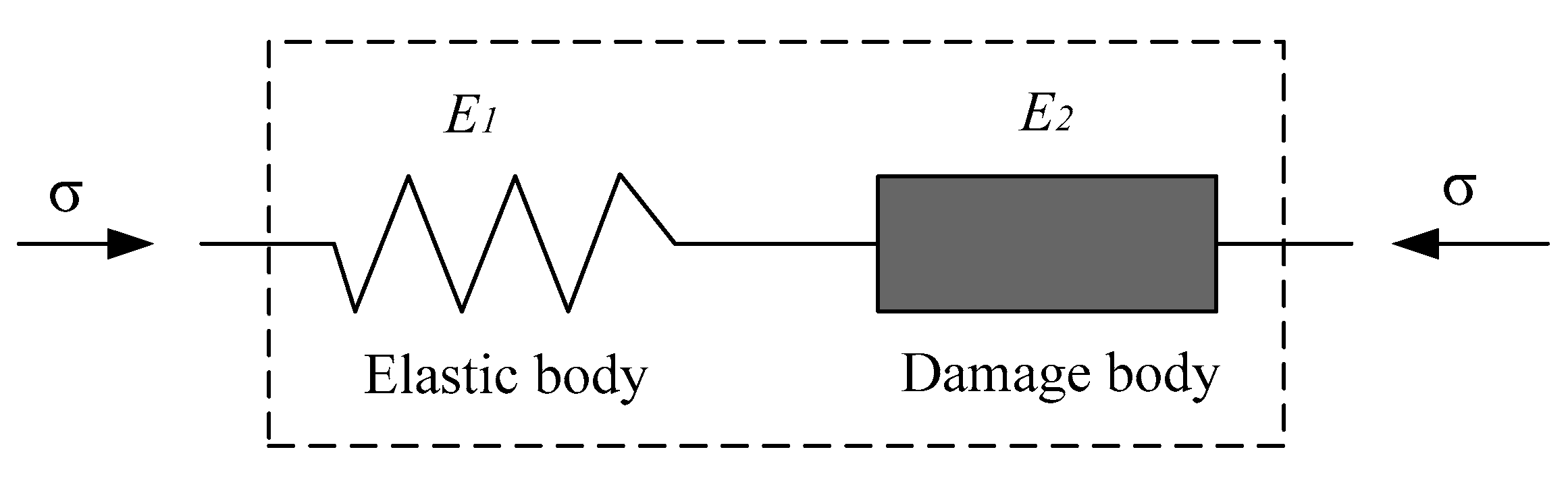
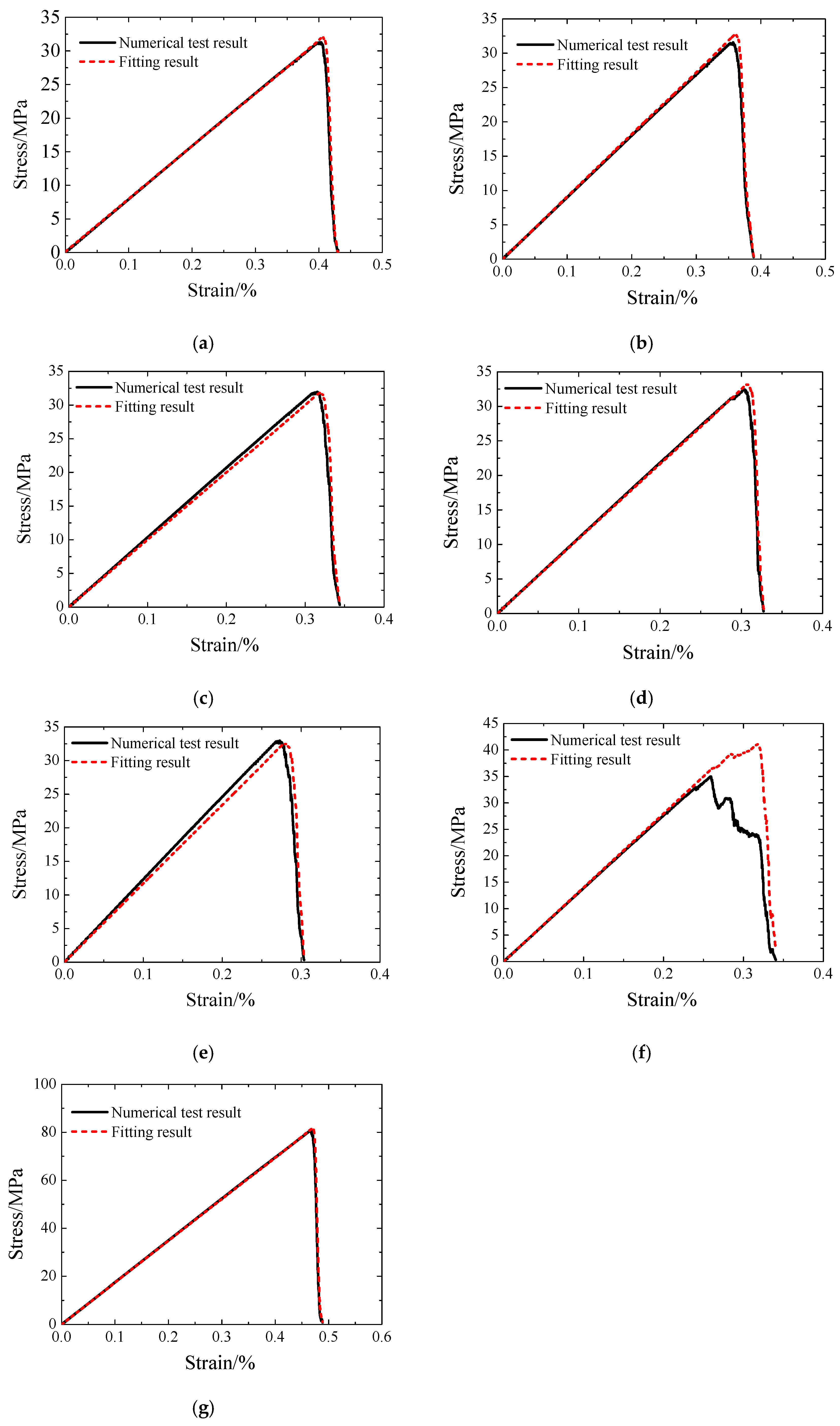
4. Damage Constitutive Model of Coal-Rock Combined Bodies

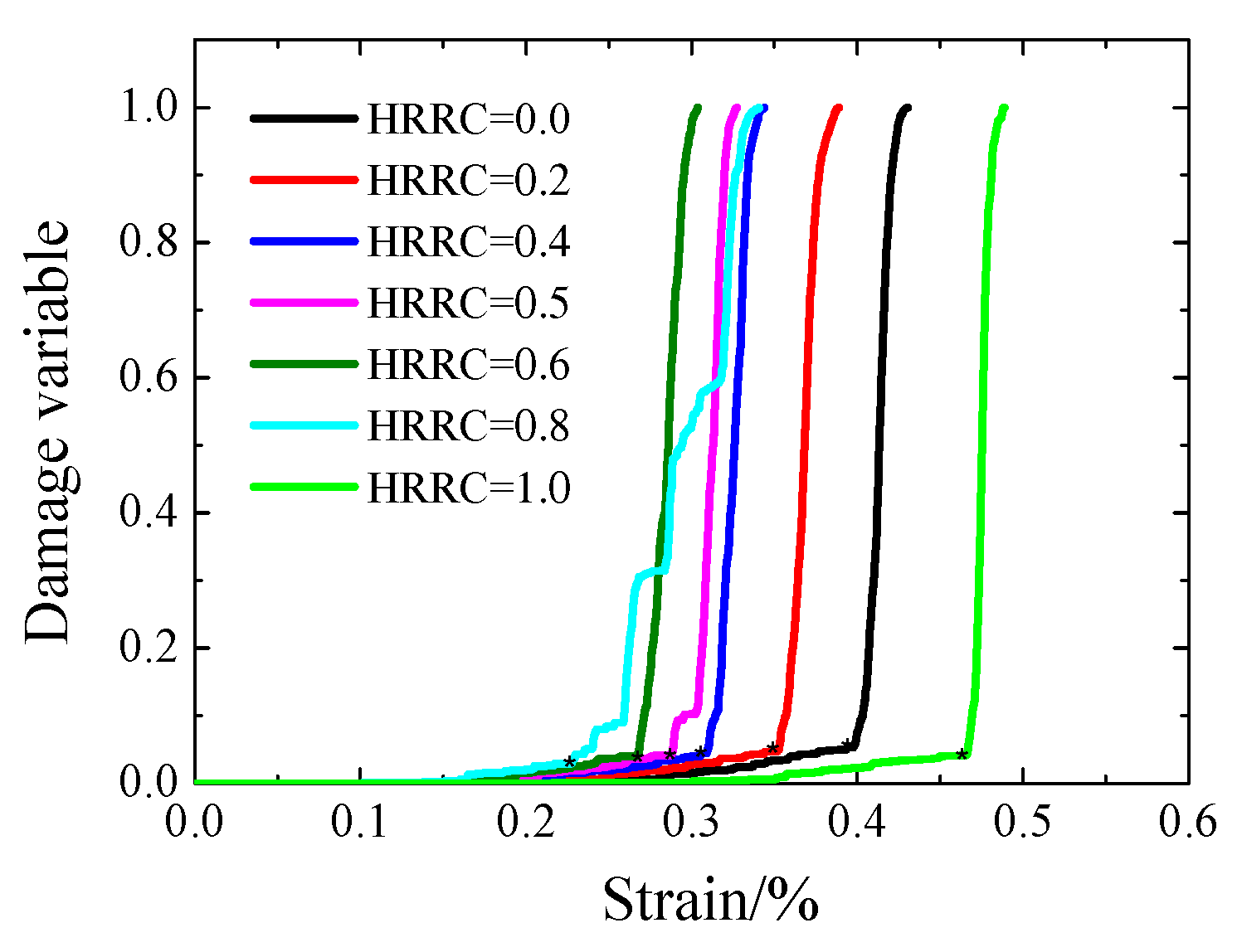
4.1. Damage Variable Based on AE Hits

Damage variables (D) can reflect the extent of damage of materials, and many parameters are used to defined it, such as yield stress, cracks, density, elastic coefficient, AE characteristics, etc. [29,30,31,32,33,34]. In this manuscript, the AE hits parameter is used to define the damage variables.
D = n N
where N is the total AE hits number of the coal-rock combined body when it fails completely, n is the total AE hits number of the coal-rock combined model from the original point to a specific time.
Owing to that it, it is hard to judge if a specimen is damaged completely during the failure process, the damage variable needs to be modified, and the modified damage variable can be expressed as [34,35]:
D = k n N
where k is the damage variable correction factor and it can be normalized as:
k = 1 σ r σ c
where σc is the peak stress of the combined coal-rock bodies during compression, and σr is the residual strength of the combined coal-rock bodies during compression.
Based on the AE hits parameter, the damage variable of the combined coal-rock body under uniaxial compression condition is established as Equation (5).
D = ( 1 σ r σ c ) n N
Figure 10 shows the damage variable curves of coal-rock combined bodies with different HRRC by Equation (5). It can be seen that the damage variable curves of coal-rock combined body have two stages. The first stage is where the damage variable increases slowly, and it corresponds to the stage of stable AE hits evolution, named the slowly damage stage. The second stage is where the damage variable increases sharply, and it corresponds to the stages of rapid ascending and rapid descending AE hits evolution, named the sharply damage stage. The watershed between the two stages is the asterisk (*) in the figure. In the slowly damage stage, as HRRC increases (expert HRRC = 1.0), the damage variable of the combined coal-rock bodies becomes shorter, and the reason is that the higher the HRRC, the lesser the coal composition, which is easier to damage in a smaller stress environment. As for the sharply damage stage, as the HRRC increases (expert HRRC = 0.8), the change of damage variable of the combined coal-rock bodies is similar. The damage variable curve fluctuating in the sharply damage stage of HRRC is equal to 0.8, and the reason for this is also related to the failure of the rock part in the coal-rock combined body.

4.2. Damage Constitutive Model of Coal-Rock Combined Bodies Based on AE Hits

From the failure modes of coal-rock combined bodies (Figure 8), it can be seen that for the combined coal-rock, the rock usually remains relatively intact (or with little damage) and the coal body is destroyed seriously. The UCS of the combined coal-rock is larger than that of the single coal body and lesser than that of the single rock body. The peak stress and elastic modulus are closely related to the HRRC, the strength and elastic modulus of the coal-rock combined bodies increase as HRRC increases. Therefore, the combined coal-rock model cannot be simply regarded as a damage body or an elastic body and should be regarded as a combined body of a damage body and an elastic body [36]. Figure 11 is the damage constitutive model of coal-rock combined body, considering the coal as a damaged body and the rock as an elastic body. The elastic modulus of Equations (1) and (2) are the elastic modulus of the single rock and the single coal, respectively.
As an elastic body, the constitutive model of the rock can be expressed as:
σ 1 = E 1 ε 1
As a damage body and based on the strain equivalence principle [37], the damaged constitutive model of the coal can be established as:
σ 2 = E 2 ε 2 ( 1 D )
where D is the damage variable of the coal body defined by the parameters of AE hits.
According to Figure 11, the damage body stress σ2, the strain ε2, and the elastic body stresses σ1 and strain ε1 satisfy the following relationship:
{ σ = σ 1 = σ 2 ε = H R R C ε 1 + α ε 2
where α = 1 − HRRC.
Bringing Equations (5)–(7) into Equation (8), the damage constitutive equation for coal-rock combined bodies can be expressed as:
σ = E 1 E 2 ε ( 1 ( 1 σ r σ c ) n N ) ( 1 H R R C ) E 1 + H R R C E 2 ( 1 ( 1 σ r σ c ) n N )
Figure 12 shows the stress-strain curves of numerical test results and fitting results according to Equation (9), with different HRRC. It can be seen that the stress-strain curves tested from numerical simulation are in good agreement with the stress-strain curves obtained from Equation (9), except for the HRRC = 0.8. As for the coal-rock combined body with HHRC, it is equal to 0.8; the fitting curve has a certain deviation, and the reason for this is that the rock part of the coal-rock combined body with HRRC = 0.8 is damaged and expands outward and the damage of the rock part is not considered in the damage constitutive equation (Equation (9)) for coal-rock combined bodies. It is indicated that the damage constitutive relation based on Equation (9) can well reflect the stress-strain relationships with a lower HRRC. However, for a higher HRRC (such as 0.8 or larger than 0.8), the damage constitutive equation is not accurately and the damage of the rock part in the coal-rock-combined body should be considered.

5. Conclusions

In this manuscript, the acoustic emission characteristics and damage constitutive model of coal-rock combined bodies with different HRRC are investigated by particle flow code; some conclusions are drawn as follows:
(1)
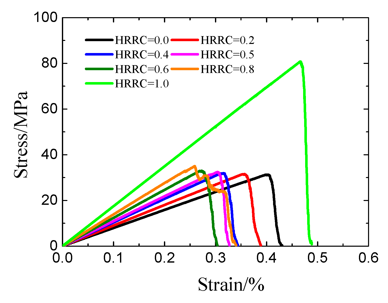
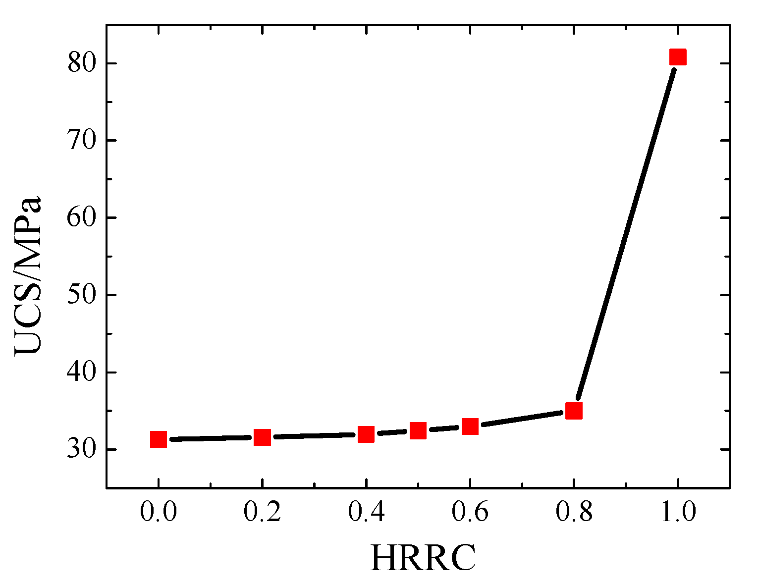
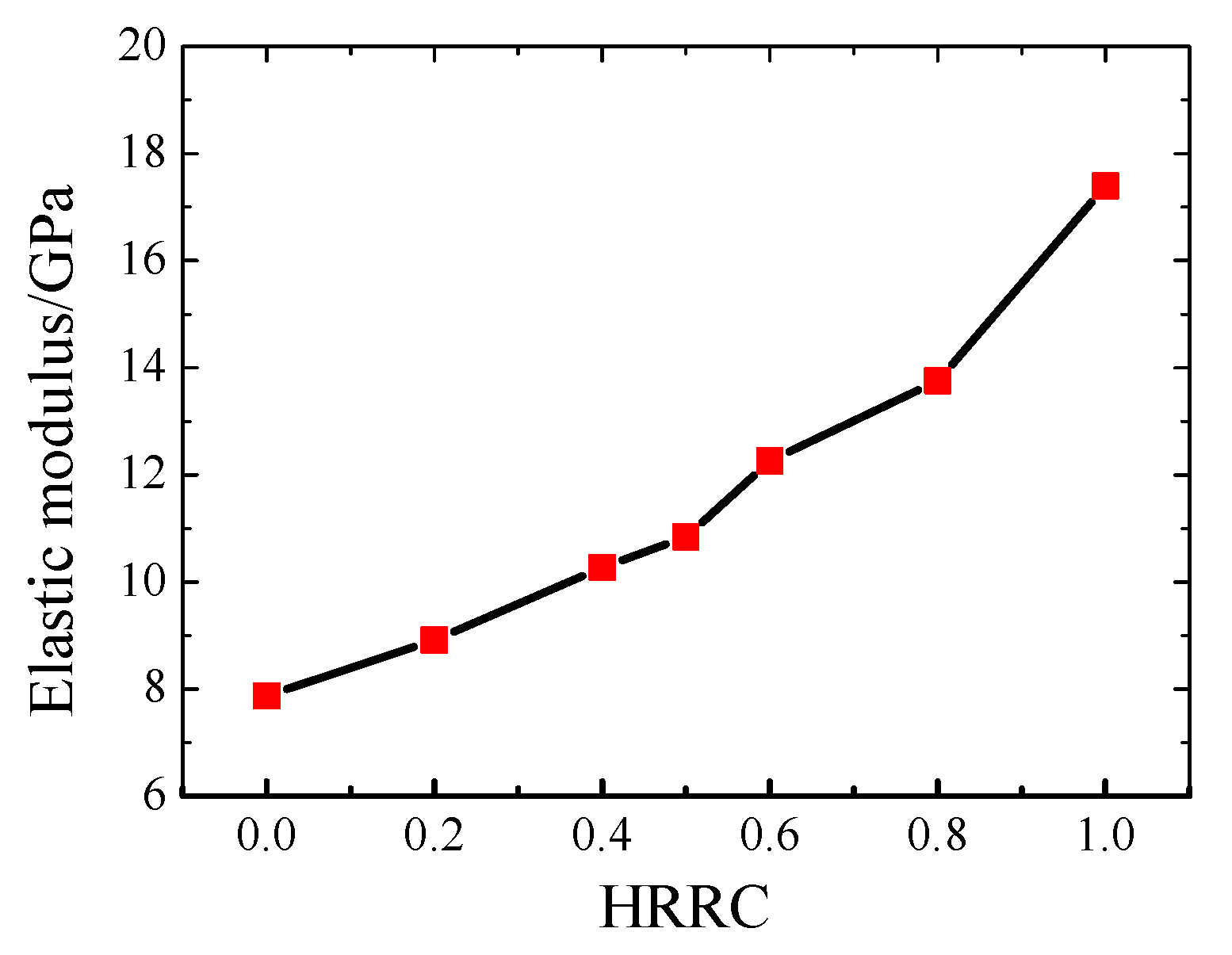
With the increase of the HRRC, the UCS and the E of the combined coal-rock bodies increase. The difference of UCS between coal-rock combined bodies (HRRC = 0.2, 0.4, 0.5, 0.6, 0.8) and coal specimen is very small, less than 4 MPa, and this shows that the strength of the coal-rock combined bodies is mainly determined by the strength of the coal body. As for E, the increase is gradual with the increase of HRRC, and this illustrates that the influence of HRRC of coal-rock combined bodies on the E is higher than on UCS.
(2)
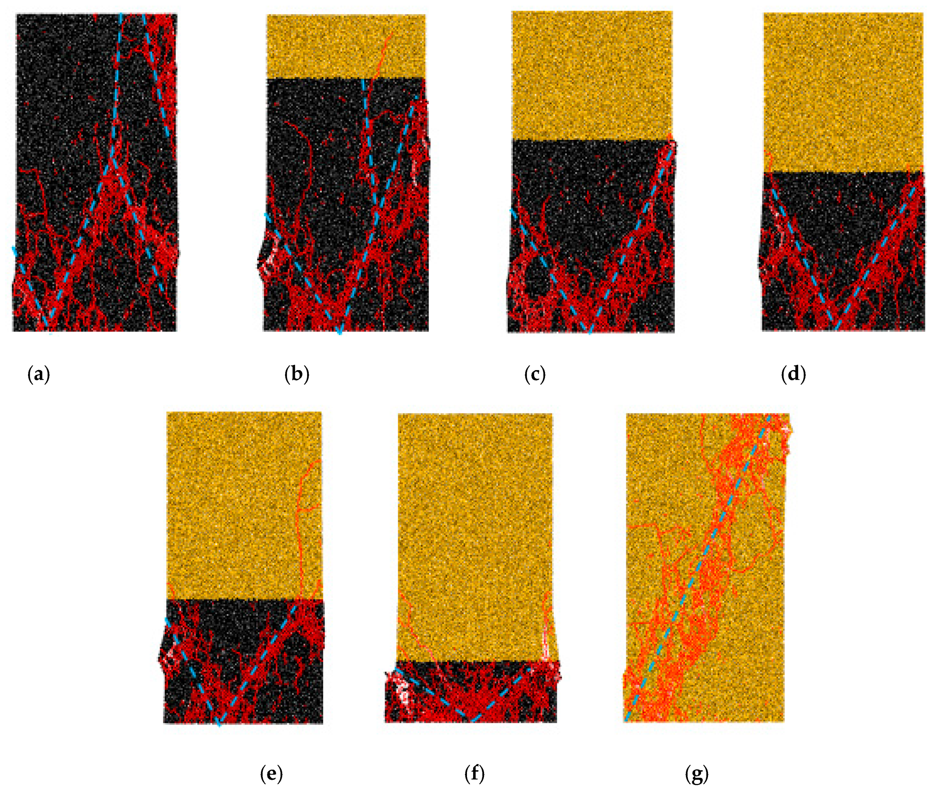
The failure of coal-rock combined bodies mainly focuses on the coal body, and this shows that the failure modes of coal-rock combined bodies are mainly controlled by the coal body. Besides HRRC = 0.0 and 1.0, the failure modes of coal-rock combined bodies are similar and have a “V” shape, and the opening of “V” become lager with the increase of the HRRC. When HRRC = 0.8, the failure parts of rock mass and coal mass expand outward, which may be the reason for the peak fluctuation of the stress-strain curve when HRRC = 0.8. When HRRC is equal to 0.0, the failure modes have an inverted “V” or inverted “Y” shape. When HRRC is equal to 1.0, the rock mass is inclined to splitting failure.
(3)
Apart from HRRC = 0.8, the evolution law of AE hits of coal-rock combined bodies are similar. The evolution law of AE hits of coal-rock combined bodies have three stages, named the stable stage, rapid ascending stage, and rapid descending stage. The maximum AE hits number of the stress-strain-AE hits curves and the total accumulated AE hits number decrease with the increase of HRRC (except HRRC = 1.0). As for HRRC = 0.8, the evolution law of the AE hits curve and accumulated AE hits curve is different from the others, and they fluctuate with the fluctuating of the stress-strain curve. The reason also comes from the failure modes of this coal-rock combined body.
(4)
The damage variable curves of coal-rock combined body have two stages, named slowly damage stage and sharply damage stage. In the slowly damage stage, with the increase of HRRC (expert HRRC = 1.0), the damage variable of the combined coal-rock bodies becomes shorter. As for the sharply damage stage, with the increase of HRRC (expert HRRC = 0.8), the damage variables of the combined coal-rock bodies are similar. The damage variable curve fluctuates in the sharply damage stage of HRRC and is equal to 0.8, and the reason for this is also related to the failure of the rock part in the coal-rock combined body.
(5)
The damage constitutive relation based on Equation (9) can well reflect the stress-strain relationships with a lower HRRC. However, for a higher HRRC (such as 0.8 or larger than 0.8), the damage constitutive equation is not accurately and the damage of the rock part in the coal-rock-combined body should be considered.

Author Contributions

X.W. provided the idea and performed the numerical simulation; W.Y. and Y.Y. analysed the data; W.L. wrote the manuscript; all authors reviewed the manuscript. Correspondence should be addressed to X.W.

Funding

This research was supported by the Key Laboratory of Safety and High-efficiency Coal Mining Ministry of Education (Anhui University of Science and Technology) (No. JYBSYS2018205), the Liaocheng University Research Fund (No. 318051703), National Natural Science Foundation of China (No. 51874006), and the Postgraduate Research & Practice Innovation Program of Jiangsu Province (No. KYCX19-0094).

Conflicts of Interest

The authors declare no conflict of interest.

References

  1. Skoczylas, N.; Wierzbicki, M. Evaluation and management of the gas and rock outburst hazard in the light of international legal regulations. Arch. Min. Sci. 2014, 59, 1119–1129. [Google Scholar] [CrossRef]
  2. Zhang, S.; Li, Y.; Shen, B.; Sun, X.; Gao, L. Effective evaluation of pressure relief drilling for reducing rock bursts and its application in underground coal mines. Int. J. Rock Mech. Min. Sci. 2019, 114, 7–16. [Google Scholar] [CrossRef]
  3. Ren, F.; Zhu, C.; He, M. Moment Tensor Analysis of Acoustic Emissions for Cracking Mechanisms During Schist Strain Burst. Rock Mech. Rock Eng. 2019. [Google Scholar] [CrossRef]
  4. Guo, W.; Gu, Q.; Tan, Y.; Hu, S. Case studies of rock bursts in tectonic areas with facies change. Energies 2019, 12, 1330. [Google Scholar]
  5. Wang, X.; Meng, F. Statistical analysis of large accidents in China’s coal mines in 2016. Nat. Hazards 2018, 92, 311–325. [Google Scholar] [CrossRef]
  6. Chen, S.; Guo, W.; Zhou, H.; Shen, B.; Liu, J. Field investigation of long-term bearing capacity of strip coal pillars. Int. J. Rock Mech. Min. Sci. 2014, 70, 109–114. [Google Scholar] [CrossRef]
  7. Newman, D. A case history investigation of two coal bumps in the southern appalachian coalfield [C]. In Proceedings of the 21st International Conference on Ground Control in Mining, West Virginia University, Morgantown, WV, USA, 6–8 August 2002; pp. 90–97. [Google Scholar]
  8. Liu, J.; Tang, C.; Zhu, W.; Yang, T. Rock-coal model for studying the rockburst. Chin. J. Geotech. Eng. 2004, 26, 276–280. [Google Scholar]
  9. Li, J.; Qi, Q.; Mao, D.; Wang, Y. Discussion on evaluation method of bursting liability with composite model of coal and rock. Chin. J. Rock Mech. Eng. 2005, 24, 4805–4810. [Google Scholar]
  10. Zuo, J.; Wang, Z.; Zhou, H.; Pei, J.; Liu, J. Failure behavior of a rock-coal-rock combined body with a weak coal interlayer. Int. J. Min. Sci. Technol. 2013, 23, 907–912. [Google Scholar] [CrossRef]
  11. Guo, W.; Tan, Y.; Yu, F.; Zhao, T.; Hu, S.; Huang, D.; Qin, Z. Mechanical behavior of rock-coal-rock specimens with different coal thicknesses. Geomech. Eng. 2018, 15, 1017–1027. [Google Scholar]
  12. Agioutantis, Z.; Kaklis, K.; Mavrigiannakis, S.; Verigakis, M.; Vallianatos, F.; Saltas, V. Potential of acoustic emissions from three point bending tests as rock failure precursors. Int. J. Min. Sci. Technol. 2016, 26, 155–160. [Google Scholar]
  13. Shkuratnik, V.L.; Filimonov, Y.L.; Kuchurin, S.V. Experimental investigations into acoustic emission in coal samples under uniaxial loading. J. Min. Sci. 2004, 40, 458–464. [Google Scholar] [CrossRef]
  14. Tan, Y.; Guo, W.; Gu, Q.; Zhao, T.; Yu, F.; Hu, S.; Yin, Y. Research on the rockburst tendency and AE characteristics of inhomogeneous coal-rock combination bodies. Shock Vib. 2016. [Google Scholar] [CrossRef]
  15. Yin, D.; Chen, S.; Liu, X.; Ma, H. Effect of joint angle in coal on failure mechanical behaviour of roof rock–coal combined body. Q. J. Eng. Geol. Hydrogeol. 2018, 51, 202–209. [Google Scholar]
  16. Cundall, P.A.; Strack, O.D.L. A discrete numerical model for granular assemblies. Geotechnique 1979, 29, 47–65. [Google Scholar] [CrossRef]
  17. Procházka, P.P. Application of discrete element methods to fracture mechanics of rock bursts. Eng. Fract. Mech. 2004, 71, 601–618. [Google Scholar]
  18. Potyondy, D.O. The bonded-particle model as a tool for rock mechanics research and application: Current trends and future directions. Geosyst. Eng. 2015, 18, 1–28. [Google Scholar]
  19. Cho, N.; Martin, C.D.; Sego, D.C. A clumped particle model for rock. Int. J. Rock Mech. Min. Sci. 2007, 44, 997–1010. [Google Scholar] [CrossRef]
  20. Wang, X.; Tian, L. Mechanical and crack evolution characteristics of coal-rock under different fracture-hole conditions: A numerical study based on particle flow code. Environ. Earth Sci. 2018, 77, 297. [Google Scholar]
  21. Liu, W. Experimental and Numerical Study of Rock Stratum Movement Characteristics in Longwall Mining. Shock Vib. 2019. [Google Scholar] [CrossRef]
  22. Zhang, Q.; Wang, X.; Tian, L.G.; Huang, D.M. Analysis of Mechanical and AE Characteristics of Rock Materials with Double-hole Defects Based on Particle Flow Code. Shock Vib. 2018. [Google Scholar] [CrossRef]
  23. Wang, X.; Wen, Z.; Jiang, Y. Time—Space effect of stress field and damage evolution law of compressed coal-rock. Geotech. Geol. Eng. 2016, 34, 1933–1940. [Google Scholar] [CrossRef]
  24. Khazaei, C.; Hazzard, J.; Chalaturnyk, R. Damage quantification of intact rocks using acoustic emission energies recorded during uniaxial compression test and discrete element modeling. Comput. Geotech. 2015, 67, 94–102. [Google Scholar] [CrossRef]
  25. Cai, M.; Kaiser, P.K.; Morioka, H.; Minami, M.; Maejima, T.; Tasaka, Y.; Kurose, H. FLAC/PFC coupled numerical simulation of AE in large-scale underground excavations. Int. J. Rock Mech. Min. Sci. 2007, 44, 550–564. [Google Scholar] [CrossRef]
  26. Zhang, X.; Zhang, Q.; Wu, S. Acoustic emission characteristics of the rock-like material containing a single flaw under different compressive loading rates. Comput. Geotech. 2017, 83, 83–97. [Google Scholar] [CrossRef]
  27. Huang, D.; Chang, X.; Tan, Y.; Zhou, J.; Yin, Y. Numerical Study of the Mechanical and Acoustic Emissions Characteristics of Red Sandstone under Different Double Fracture Conditions. Symmetry 2019, 11, 772. [Google Scholar] [CrossRef]
  28. Zuo, J.; Xie, H.; Wu, A.; Liu, J. Investigation on failure mechanisms and mechanical behaviors of deep coal-rock single body and combined body. Chin. J. Rock Mech. Eng. 2011, 30, 84–92. [Google Scholar]
  29. Murti, V.; Zhang, W.; Valliappan, S. Stress invariants in an orthotropic damage space. Eng. Fract. Mech. 1991, 40, 985–990. [Google Scholar] [CrossRef]
  30. Kim, J.; Yi, J.; Kim, J.; Zi, G.; Kong, J.S. Fatigue life prediction methodology using entropy index of stress interaction and crack severity index of effective stress. Int. J. Damage Mech. 2013, 22, 375–392. [Google Scholar]
  31. Kupchella, R.; Stowe, D.; Xiao, X.; Algoso, A.; Cogar, J. Incorporation of material variability in the Johnson Cook model. Procedia Eng. 2015, 103, 318–325. [Google Scholar] [CrossRef]
  32. Mizuno, M.; Okayasu, M.; Odagiri, N. Damage evaluation of piezoelectric ceramics from the variation of the elastic coefficient under static compressive stress. Int. J. Damage Mech. 2010, 19, 375–390. [Google Scholar] [CrossRef]
  33. Aggelis, D.G. Classification of cracking mode in concrete by acoustic emission parameters. Mech. Res. Commun. 2011, 38, 153–157. [Google Scholar] [CrossRef]
  34. Wang, X.; Wen, Z.; Jiang, Y.; Huang, H. Experimental study on mechanical and acoustic emission characteristics of rock-like material under non-uniformly distributed loads. Rock Mech. Rock Eng. 2018, 51, 729–745. [Google Scholar] [CrossRef]
  35. Zong, Y.; Han, L.; Wei, J.; Wen, S. Mechanical and damage evolution properties of sandstone under triaxial compression. Int. J. Min. Sci. Technol. 2016, 26, 601–607. [Google Scholar]
  36. Liu, X.; Tan, Y.; Ning, J.; Lu, Y.; Gu, Q. Mechanical properties and damage constitutive model of coal in coal-rock combined body. Int. J. Rock Mech. Min. Sci. 2018, 110, 140–150. [Google Scholar] [CrossRef]
  37. Lemaitre, J.; Sermage, J.P.; Desmorat, R. A two scale damage concept applied to fatigue. Int. J. Fract. 1999, 97, 67–81. [Google Scholar] [CrossRef]
Figure 1. Contact bond (CB) and parallel bond (PB) models of particle flow code [19,20]. (a) Contact bond model (CBM); (b) Parallel bond model (PBM).
Symmetry 11 01040 g001
Figure 2. Comparison of stress-strain curves and failure modes of real rock specimen and PFC rock specimens [22]. (a) Stress-strain curves; (b) Failure modes.
Symmetry 11 01040 g002
Figure 3. Comparison of stress-strain curves and failure modes of real coal specimen and PFC coal specimens [23]. (a) Stress-strain curves; (b) Failure modes.
Symmetry 11 01040 g003
Figure 4. The combined coal-rock models with different HRRC. (a) HRRC = 0.0; (b) HRRC = 0.2; (c) HRRC = 0.4; (d) HRRC = 0.5; (e) HRRC = 0.6; (f) HRRC = 0.8; (g) HRRC = 1.0.
Symmetry 11 01040 g004
Figure 5. Stress-strain curves of numerical coal-rock combined bodies with different HRRC.
Symmetry 11 01040 g005
Figure 6. UCS of coal-rock combined bodies with different HRRC.
Symmetry 11 01040 g006
Figure 7. Elastic modulus of coal-rock combined bodies with different HRRC.
Symmetry 11 01040 g007
Figure 8. Failure modes of numerical coal-rock combined bodies with different HRRC. (a) HRRC = 0.0; (b) HRRC = 0.2; (c) HRRC = 0.4; (d) HRRC = 0.5; (e) HRRC = 0.6; (f) HRRC = 0.8; (g) HRRC = 1.0.
Symmetry 11 01040 g008
Figure 9. Stress-strain-AE hits curves of coal-rock combined bodies with different HRRC. (a) HRRC = 0.0; (b) HRRC = 0.2; (c) HRRC = 0.4; (d) HRRC = 0.5; (e) HRRC = 0.6; (f) HRRC = 0.8; (g) HRRC = 1.0.
Symmetry 11 01040 g009aSymmetry 11 01040 g009b
Figure 10. Curves of damage variable of coal-rock combined model.
Symmetry 11 01040 g010
Figure 11. The damage constitutive model of coal-rock combined body.
Symmetry 11 01040 g011
Figure 12. Fitting stress-strain curves of coal-rock combined bodies with different HRRC. (a) HRRC = 0.0; (b) HRRC = 0.2; (c) HRRC = 0.4; (d) HRRC = 0.5; (e) HRRC = 0.6; (f) HRRC = 0.8; (g) HRRC = 1.0.
Symmetry 11 01040 g012
Table 1. Meso-parameters of numerical rock model [22].
ParameterValueParameterValue
Minimum particle diameter (mm)0.4Porosity0.1
Particle diameter ratio1.5Parallel bond friction angle (°)38
Density (kg/m3)2440Parallel bond tensile strength (MPa)27.8
Contact modulus of the particle (GPa)4.0Normal critical damping ratio0.5
Parallel bond Deformation modulus (GPa)27Parallel bond Cohesive force (MPa)39
Contact bond gap (mm)0.05Stiffness ratio1.0
Table 2. Meso-parameters of numerical coal model [23].
ParameterValueParameterValue
Minimum particle diameter/mm0.3Porosity0.1
Particle diameter ratio1.66Coefficient of friction0.46
Density/(kg/m3)1800Parallel bond Compressive strength/MPa10
Contact modulus of the particle/GPa1.0Parallel bond friction angle/degree25
Parallel bond Deformation modulus/GPa12Parallel bond Cohesive force/MPa16
Contact bond gap/mm0.05Stiffness ratio1.0
Normal critical damping ratio0.5

