Digital Watermarking Image Compression Method Based on Symmetric Encryption Algorithms

Abstract
:1. Introduction
2. Algorithmic Definitions
2.1. Digital Watermarking Image Based on Symmetric Encryption
2.1.1. Wavelet Transform of Image
2.1.2. Watermarking Generation (Arnold Permutation)
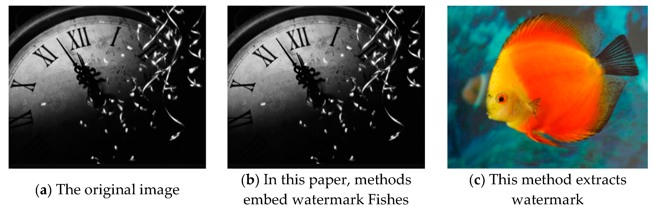
2.1.3. Watermarking Embedding and Extraction
- (1)
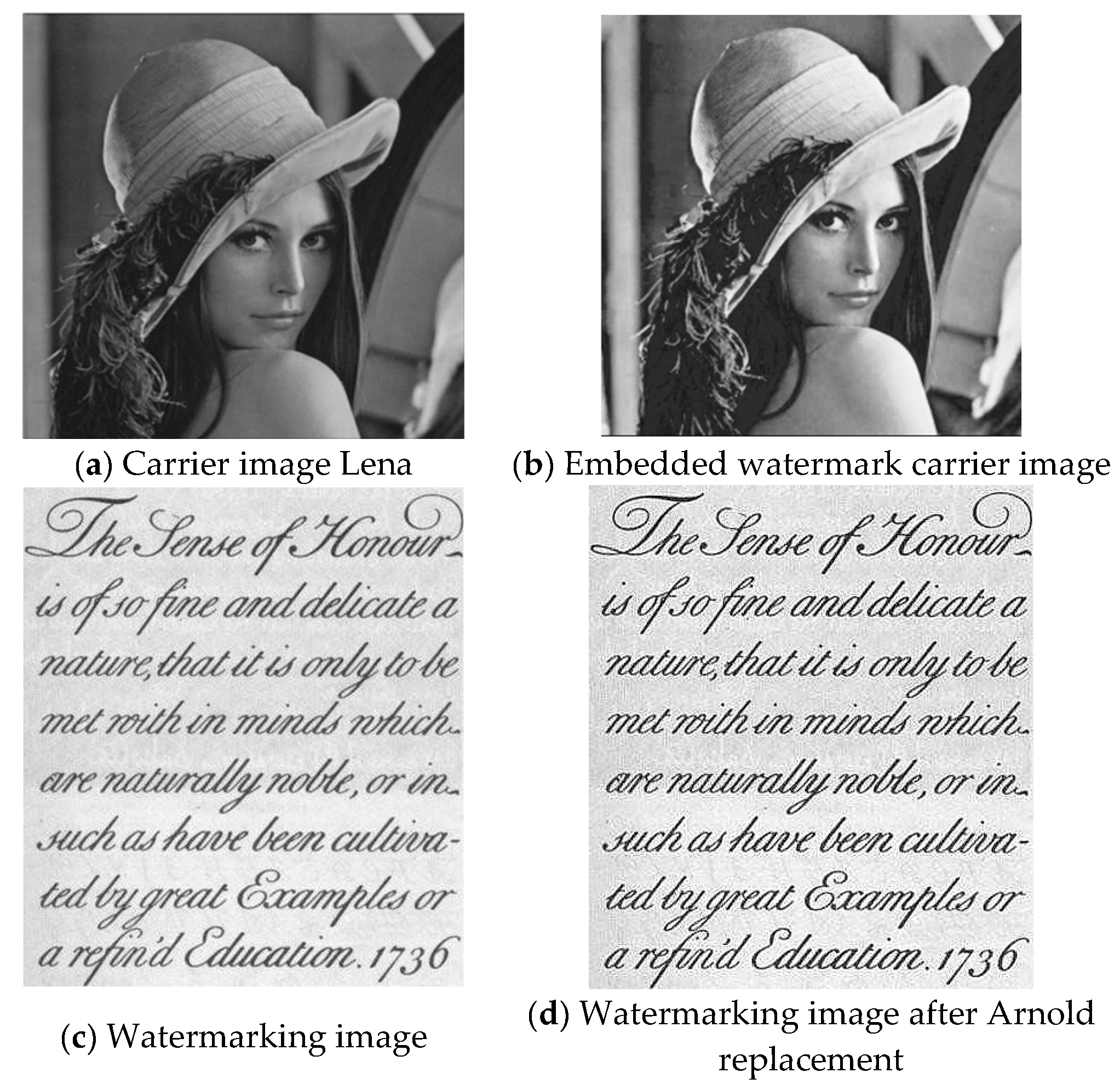
- Arnold transform is used to scramble the watermarking image, and the scrambled watermarking is recorded as .
- (2)
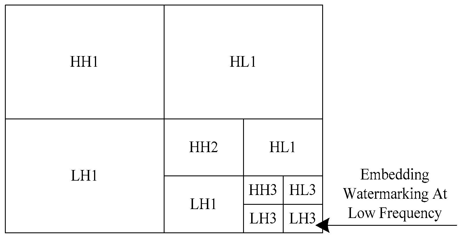
- The original image is transformed by a three-level wavelet transform to obtain sub-images in different directions at different resolutions.
- (3)
- is decomposed into four subgraphs by first-order wavelet decomposition.
- (4)
- The data in the watermarking and the data in the original image subgraph are coded in blocks according to the following formula:where is the DWT coefficient before embedding, is the wavelet strength parameter, is the embedding watermarking, and represents the embedding watermarking. Subgraphs with different intensities and in different directions allow the embedded watermarking to have a certain degree of self-adaptability.
2.1.4. Watermarking Detection
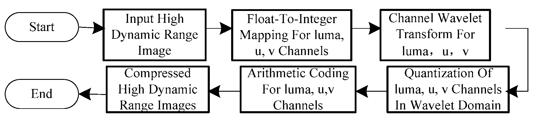
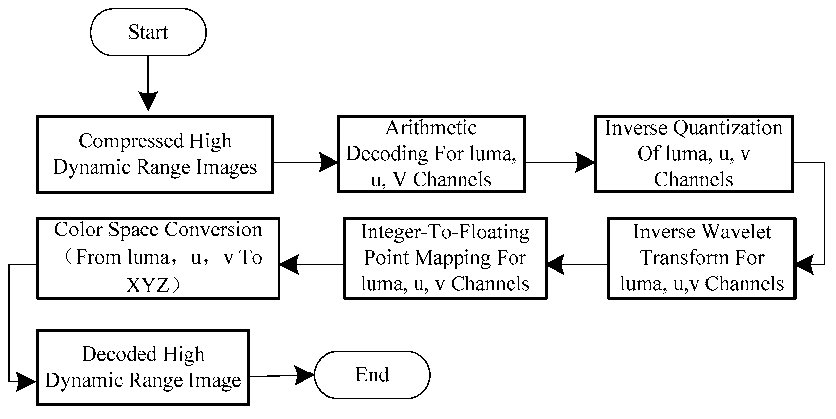
2.2. Design of Symmetric Encryption Digital Watermarking Image Compression Algorithm
3. Results
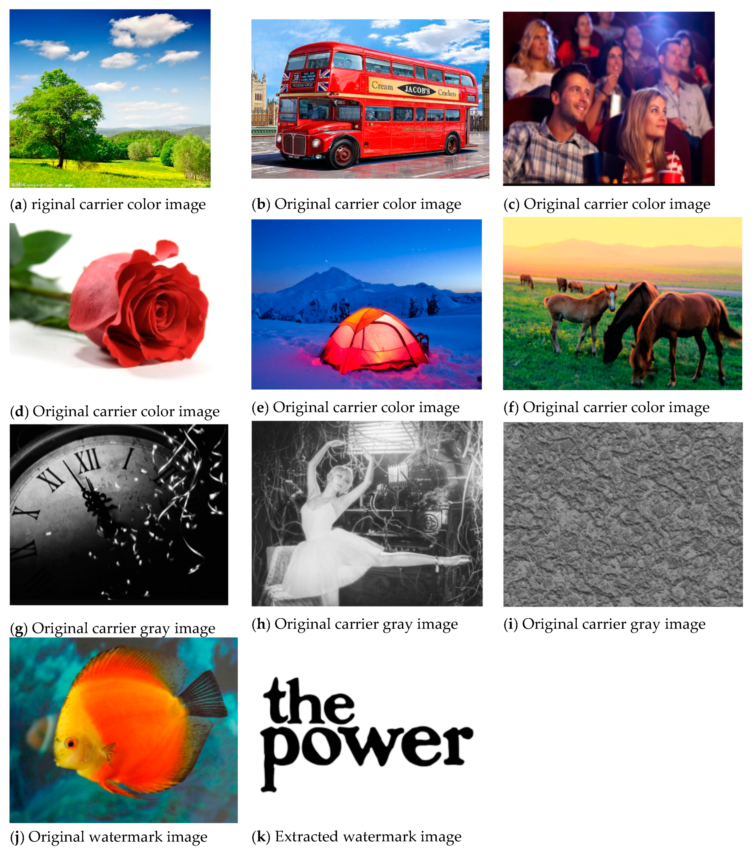
3.1. Transparency Experiment
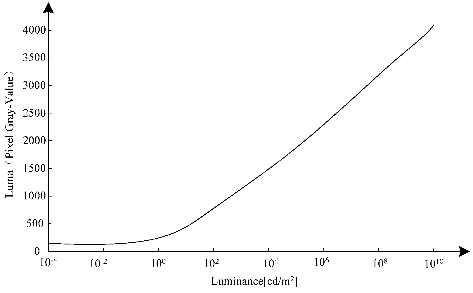
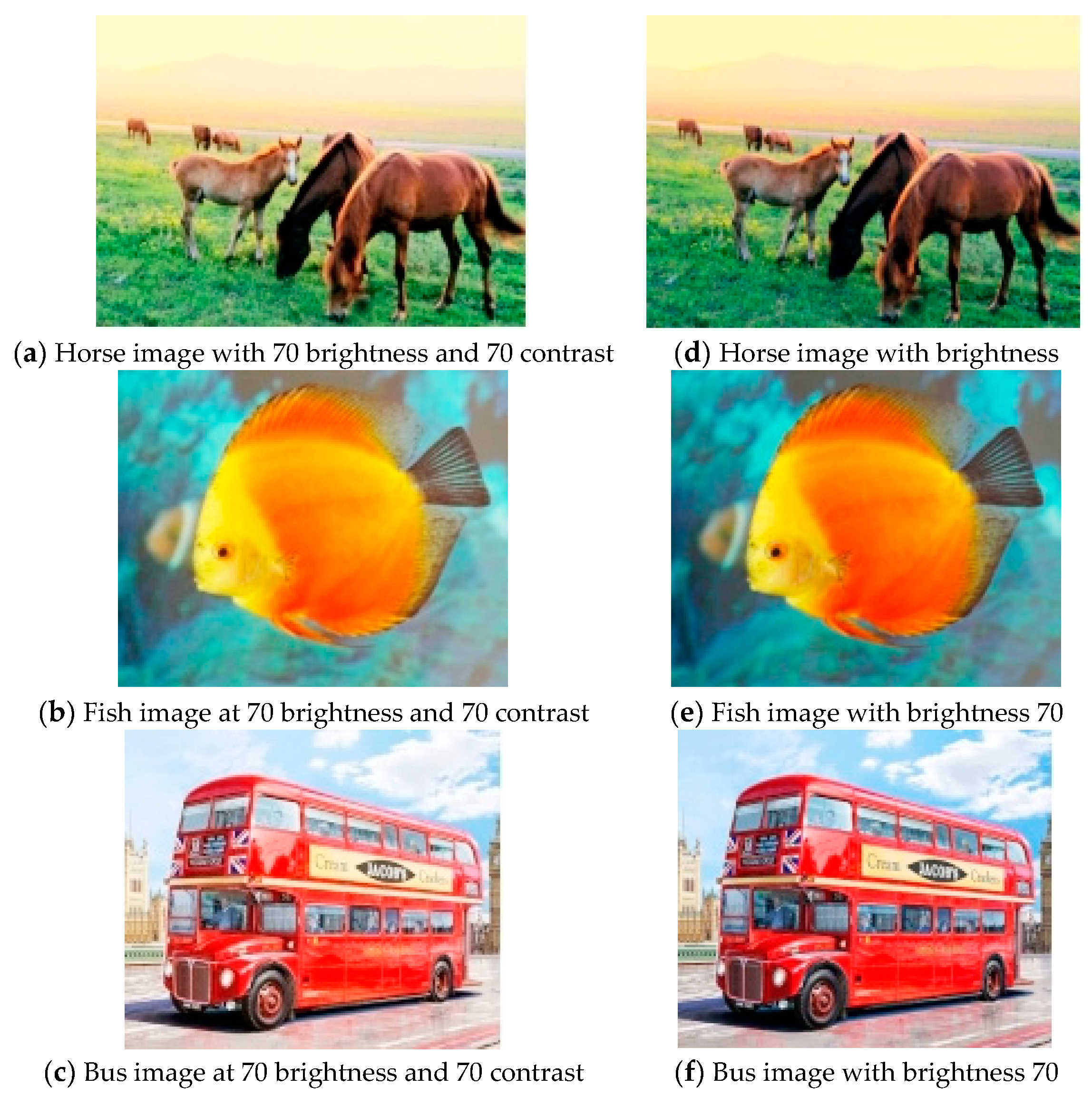
3.2. Anti-Brightness/Contrast Attack Performance Detection
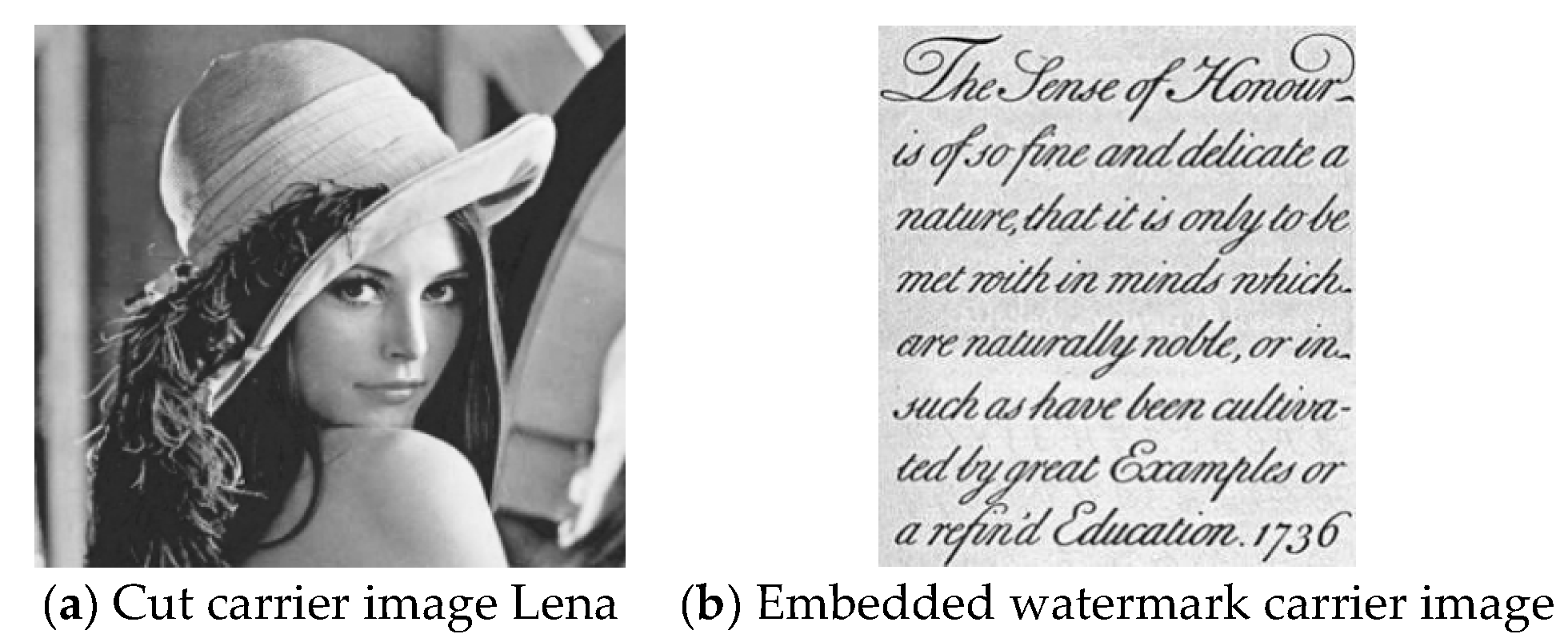
3.3. Testing of Shear Resistance
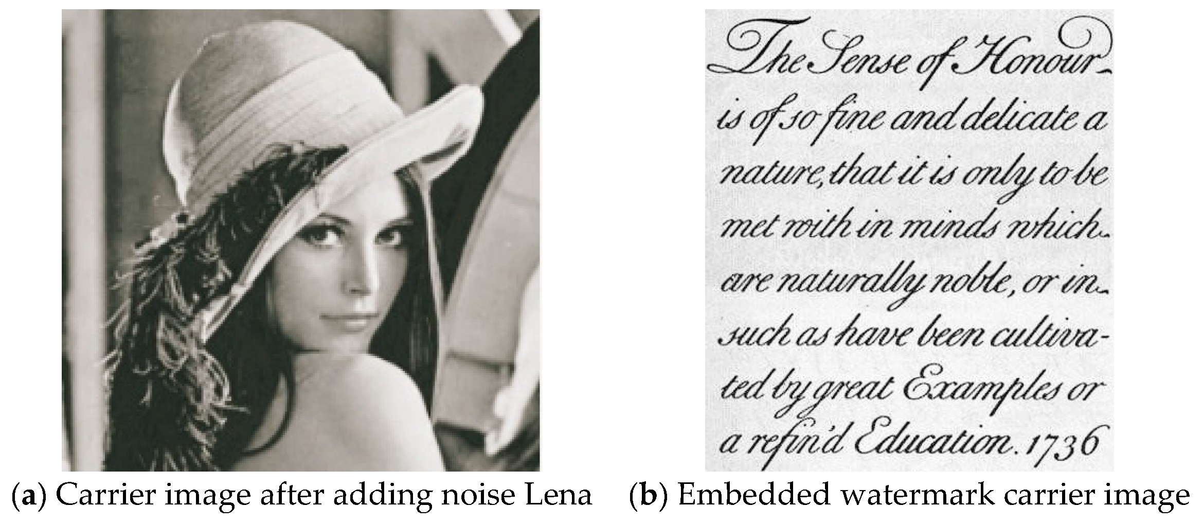
3.4. Anti-Noise Performance Testing
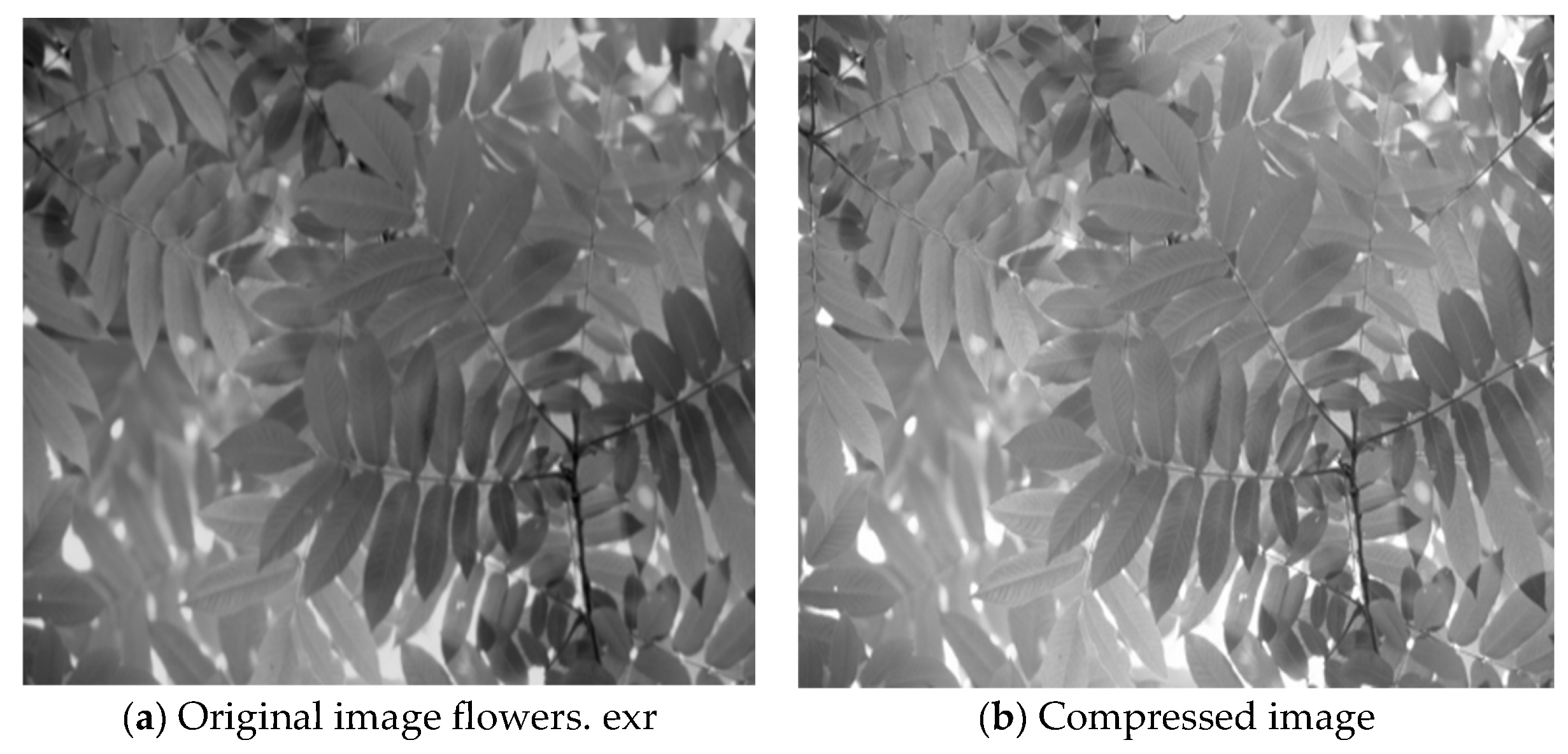
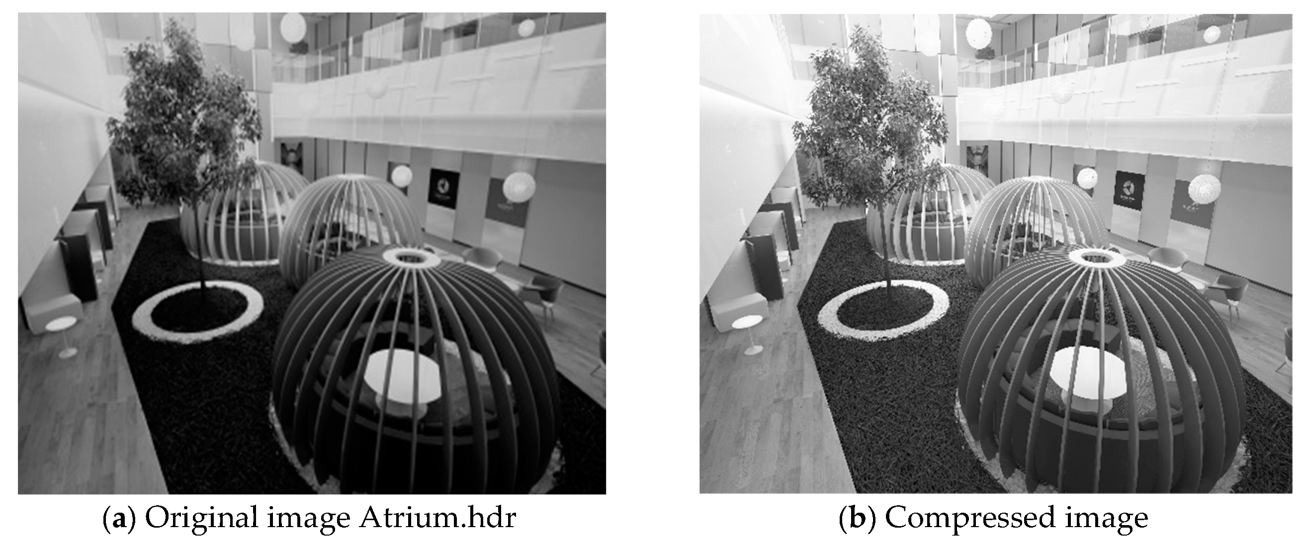
3.5. Digital Watermarking Image Compression Detection Based on Symmetric Encryption
4. Conclusions
Author Contributions
Funding
Conflicts of Interest
References
- Yin, X.; Huang, W.Q. Research on Color QR Code Watermarking Technology Based on Chaos Theory. J. Commun. 2018, 373, 54–62. [Google Scholar]
- Wei, Q.L.; Sun, Q.Q. Digital Watermarking Algorithm Based on Contourlet Transform and SVD. Comput. Eng. Des. 2017, 38, 2369–2373. [Google Scholar]
- Zhan, W.; Duan, X.H.; Yu, Y.C. Research on Image Compression Coding Method Based on Wavelet Transform. Comput. Technol. Dev. 2018, 28, 21–25. [Google Scholar]
- Gu, F.M. The Compressed Video Image Multiple Digital Watermarking Hiding Method Simulation. Comput. Simul. 2017, 34, 199–202. [Google Scholar]
- Zeng, C.; Yang, W.P. Research on Digital Watermarking Algorithm Based on DCT Transform for Image Copyright Protection. Bull. Sci. Technol. 2018, 109, 119–122. [Google Scholar]
- Wu, C.M.; Zheng, H.K.; Wang, Y.J.; Fu, R.; Yu, M.; Sun, Y. An Image Compression Algorithm Based on Multi-node Cooperation in Wireless Multimedia Sensor Networks. Trans. Beijing Inst. Technol. 2018, 38, 109–114. [Google Scholar]
- Li, S.Q.; Li, G.Q.; Xian, C.H. Eigenvector-Based Watermarking for 3D MeshModels. J. Graph. 2017, 38, 155–161. [Google Scholar]
- Dahmani, Z.; Abdellaoui, M.A. Ona Three Point Boundary Value Problem of Arbitrary Order. J. Interdiscip. Math. 2016, 19, 893–906. [Google Scholar] [CrossRef]
- Liao, R.H.; Sun, C.Q.; Liu, H. Fractional Fourier M-Band Dual-tree Complex Waveletand SVD Based Digital Watermarking Algorithm. Control Eng. China 2017, 24, 1432–1438. [Google Scholar]
- Delgado, J.; Peña, J.M. Monotonicity Preserving Representations of Curves and Surfaces. Appl. Math. Nonlinear Sci. 2016, 1, 517–528. [Google Scholar] [CrossRef] [Green Version]
- Gong, M.L.; Zhang, W.; Wang, F.C. Image Compression Confidentiality Based on Compression Sensing Algorithm. J. Detect. Control 2017, 39, 106–110. [Google Scholar]
- Ma, Z.; Sun, Y. An Application of -Expansion Method to the Dispersive Water System. J. Interdiscip. Math. 2016, 19, 335–344. [Google Scholar] [CrossRef]
- Wang, C.H.; Han, D. An Effective Blind Forensics Detection Scheme of Median Filtering Image. J. China Acad. Electron. Inf. Technol. 2017, 12, 668–674. [Google Scholar]
- Shen, Y.X.; Wu, J.; Wu, D.H. Fault Diagnosis Technology for Three-level Inverter Based on Reconstructive Phase Space and SVM. J. Power Supply 2017, 15, 114–121. [Google Scholar]
- Maldonado, M.; Prada, J.; Senosiain, M.J. On Linear Operators and Bases on Köthe Spaces. Appl. Math. Nonlinear Sci. 2016, 1, 617–624. [Google Scholar] [CrossRef] [Green Version]
- Liu, L.P.; Yin, J.T. Image Analysis of Chromium Doping on LiMn2O4 Spinel High Temperature Solubility. Chin. J. Power Sources 2017, 41, 1121–1123. [Google Scholar]
- Lai, J.L.; Zhang, F.Q. Multimedia Image Reconstruction Based on Virtual Reality. Autom. Instrum. 2018, 46, 236–239. [Google Scholar]
- Zhang, H. Digital Image Watermarking Algorithm Based on Compressive Sensing and Discrete Cosine Transform. J. Jilin Univ. (Sci. Ed.) 2017, 55, 1504–1510. [Google Scholar]
- Liang, L.X.; Tang, L.H.; Bai, W.W. Simulation of Double Digital Watermarking Algorithm for Color Image. Comput. Simul. 2017, 34, 150–153. [Google Scholar]
- Pyskunov, S.O.; Maksimyk, Y.V.; Valer, V.V. Finite Element Analysis of Influence of Non-homogenous Temperature Field on Designed Lifetime of Spatial Structural Elements under Creep Conditions. Appl. Math. Nonlinear Sci. 2016, 1, 253–262. [Google Scholar] [CrossRef] [Green Version]


| Analytical Low Pass Filter | Analytical High Pass Filter | Synthetic Low Pass Filter | Synthetic High Pass Filter |
|---|---|---|---|
| 0.026748757411 | 0 | 0 | 0.026748757411 |
| −0.016864118443 | 0.091271763114 | −0.091271763 | 0.016864118443 |
| −0.078223266529 | −0.057543526229 | −0.057543526229 | −0.078223266529 |
| 0.266864118443 | −0.591271763114 | 0.591271763114 | −0.266864118443 |
| 0.602949018236 | 1.11508705 | 1.11508705 | 0.602949018236 |
| 0.266864118443 | −0.591271763114 | 0.591271763 | −0.266864118443 |
| −0.078223266529 | −0.057543526229 | −0.057543526229 | −0.078223266529 |
| −0.016864118443 | 0.091271763114 | −0.091271763114 | 0.016864118443 |
| 0.026748757411 | 0 | 0 | 0.026748757411 |
| PSNR | PSNRR | PSNRG | PSNRB | |
|---|---|---|---|---|
| a | 45.7884 | 44.5741 | 45.7002 | 47.0909 |
| b | 45.6866 | 44.9539 | 45.6302 | 46.4757 |
| c | 45.1864 | 44.3810 | 45.0482 | 46.1301 |
| d | 45.6693 | 45.0324 | 45.6056 | 46.3700 |
| e | 46.0259 | 45.2301 | 46.0145 | 46.8602 |
| f | 45.8591 | 45.0048 | 45.6675 | 46.6050 |
| g | 46.6032 | 45.8702 | 46.2284 | 46.6032 |
| h | 44.8100 | - | - | - |
| i | 45.6100 | - | - | - |
| Image Name | Original Size (byte) | Compressed Graph Size (byte) | Pixel Percentages of Image Differences Visible to the Naked Eye | Root Mean Square Error | Time (second) | |
|---|---|---|---|---|---|---|
| Probability >75% | Probability >95% | |||||
| Crissy Field. exr | 1,304,619 | 750,382 | 0% | 0% | 1.7327 | 5″0 |
| Flowers exr | 758,083 | 200,512 | 0% | 0% | 1.8101 | 4″7 |
| MtTamNorth. exr | 1,422,492 | 487,324 | 0% | 0% | 2.8594 | 4″9 |
| Cis front. hdr | 7,893,724 | 640,179 | 0.01% | 0% | 0.3659 | 17″6 |
| atrium. hdr | 8,110,240 | 360,418 | 0.36% | 0.11% | 0.0515 | 17″3 |
| Parking lot. hdr | 7,767,193 | 666,102 | 0.01% | 0% | 0.3025 | 17″2 |
| rooftops. hdr | 7,336,883 | 500,505 | 0% | 0% | 0.1733 | 15″3 |
| Albers. hdr | 6,444,172 | 463,477 | 0% | 0% | 0.4152 | 15″7 |
© 2019 by the authors. Licensee MDPI, Basel, Switzerland. This article is an open access article distributed under the terms and conditions of the Creative Commons Attribution (CC BY) license (http://creativecommons.org/licenses/by/4.0/).
Share and Cite
Tan, Y.; Zhao, Y. Digital Watermarking Image Compression Method Based on Symmetric Encryption Algorithms. Symmetry 2019, 11, 1505. https://doi.org/10.3390/sym11121505
Tan Y, Zhao Y. Digital Watermarking Image Compression Method Based on Symmetric Encryption Algorithms. Symmetry. 2019; 11(12):1505. https://doi.org/10.3390/sym11121505
Chicago/Turabian StyleTan, Yanli, and Yongqiang Zhao. 2019. "Digital Watermarking Image Compression Method Based on Symmetric Encryption Algorithms" Symmetry 11, no. 12: 1505. https://doi.org/10.3390/sym11121505