1. Introduction
In the beginning of the twentieth century, the main diagnostic imaging technique was radiology. Since then, more modern image acquisition and reproduction systems have been used, one of which is computerized tomography (CT), a tool that provides surgeons with detailed images of a patient’s anatomy (F. Cavas-Martínez et al., 2018).
This work highlights the evolution of surgical planning; it illustrates how the process can be transferred from the virtual world (CT images) to the physical world, applying technologies such as 3D printing to the realization of three-dimensional anatomical parts.
Tomographic images are, however, part of the new workflow, as they represent the first step in the process. Specific software is required to help the technician convert TAC images (DICOM format) into a format that can be understood first by Computer Aided Design (CAD) software and then by 3D printing software.
The uniqueness, irregularity, and complexity of the human anatomy represent a challenge to the development of the aforementioned models; for this reason, the intervention of competent professionals is necessary, both in the engineering and medical fields.
Many paths lead to the TAC model 3D model conversion; however, in this work, we will illustrate a procedure that has already been implemented several times—one that works and uses the following SWs: InVesalius (open source software developed since 2001 by Centro de Tecnologia da Informação Renato Archer (CTI), Brazil), MeshLab (developed by the ISTI - CNR research center, Pisa, Italy), and Meshmixer (developed by Autodesk, San Rafael, CA, USA).
The sample of patients involved is 10 out of 25, in reference to the population that annually undergoes resection of tarsal coalition.
The main purpose of this work is to demonstrate the economic improvement achieved by the implementation of the described procedure [
1].
This pilot study highlights the numerous advantages of the proposed model for patients, doctors, and hospitals. The patient has a better awareness of his clinical situation, knowing that the tailored surgical treatment is safer and less invasive. The doctor, on the other hand, receives a better perception of the structure and geometry of the bone, and is able to simulate surgical intervention using the prototype, thus predicting its result. Hospitals gain to benefit from the reduction of risks, complications, and infections.
A Strengths Weaknesses Opportunities Threats (SWOT) analysis was also carried out in order to understand this innovative procedure better, analyzing its strengths and weaknesses, and glimpsing external threats and future developments.
It should also be emphasized that 3D printing in the medical field has several recipients, including the production of prostheses and the use of reconstructions for educational purposes. However, it is important to note that in this research work, 3D printing is only used for diagnostic purposes; in particular, the implementation of a case study concerning the three-dimensional reproduction of feet for patients suffering from flat feet. The aim herein is to improve the diagnostic process and thereby boost the treatment of specific pathologies.
Reference is made to the state of the art concerning case studies applied to other orthopedic pathologies [
2].
2. State of the Art: The Flat Foot Pathology
2.1. Diagnosis
Flat foot is a common childhood condition [
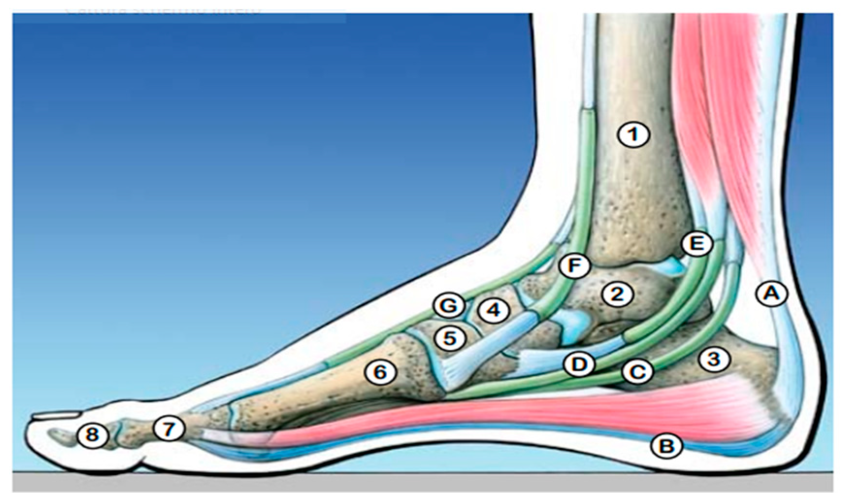
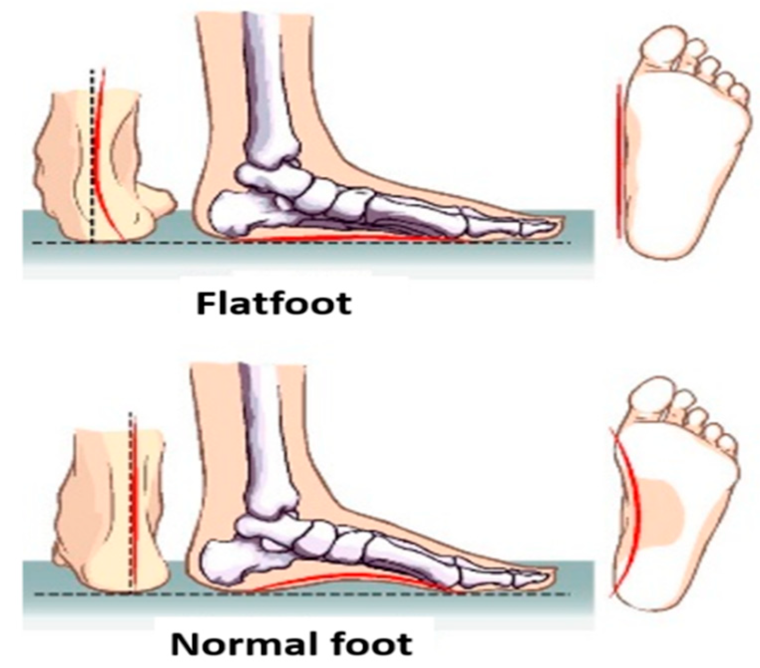
3] that can cause pain and an altered gait. This pathology is determined by the fall of the plantar arch and the valgus pronation of the heel [
4]. It tends to lean towards the inside and the rest of the foot tends to point outwards, causing the pathology (
Figure 1 and
Figure 2).
In the first phase of walking, up to three years, this condition is completely normal and is part of the physiological growth of the foot. After the age of three, if the plantar arch is not correctly formed, an insole may support and promote the formation of the plantar arch. If this does not lead to an improvement of the plantar arch within 8–9 years, corrective surgery is recommended between 9 and 14 years in case of pain, fatigue and discomfort of the feet. Flat feet cause imbalances of load at the level of the foot and at the level of posture and can therefore have painful symptoms.
Flatfoot has been traditionally classified in “flexible” and “rigid”. Whether flexible flatfoot is generally asymptomatic, rigid flatfoot is frequently associated with pain and symptoms that start during the transition from childhood to adolescence. At this age, in fact, boys and girls are more deeply involved in sport activities that can exacerbate the symptoms of a rigid flatfoot. Although several causes may lead to a rigid flatfoot, tarsal coalition is the most common condition associated to the rigid flat foot. Tarsal coalition is a congenital anomaly characterized by a partial or complete fusion between two or more midfoot or hindfoot bones, due to abnormal formation of bone, cartilage or fibrous tissue [
6].
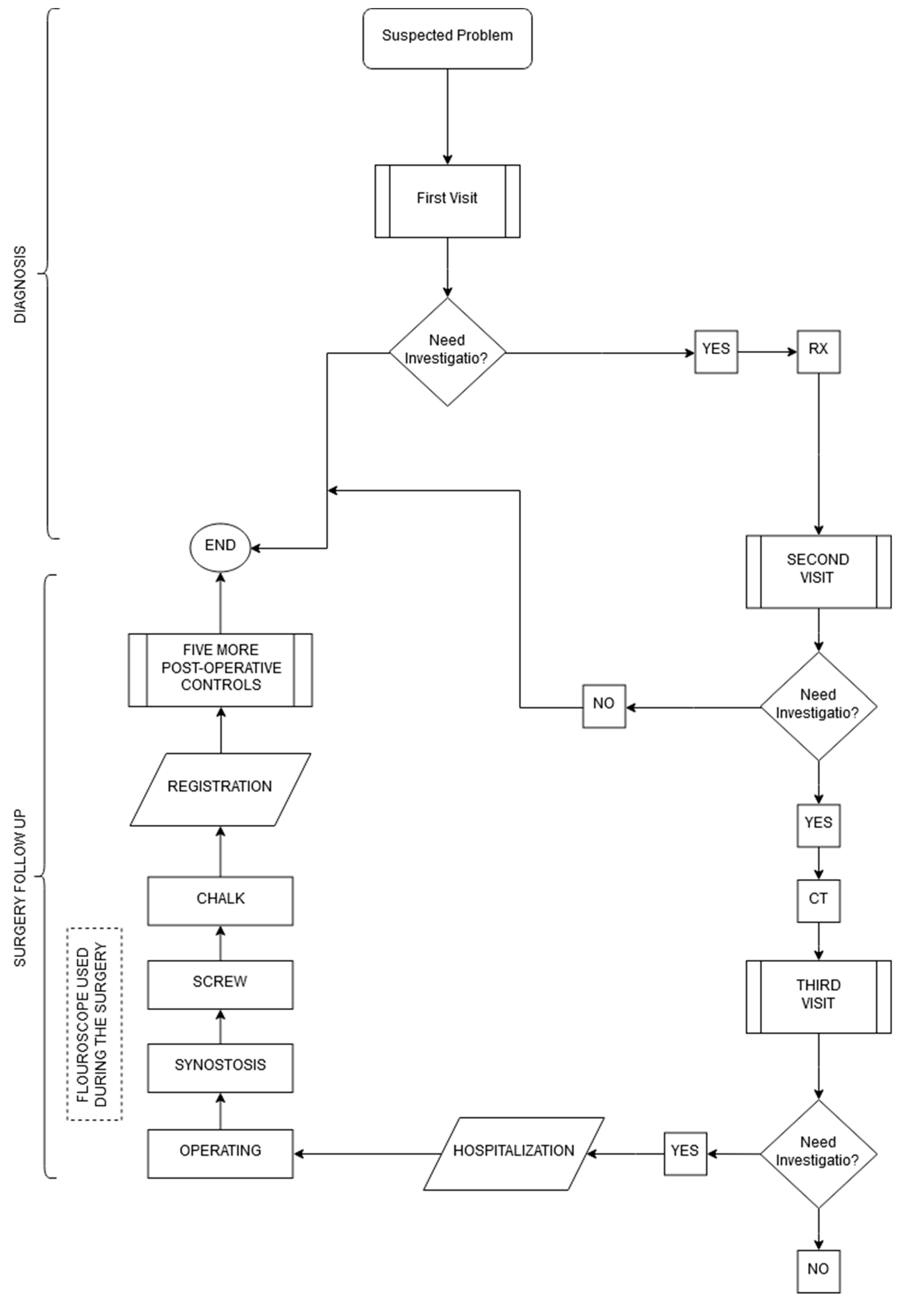
Focusing on subjects suffering from tarsal coalition, in the latest years, we developed an original surgical technique, that allows to remove in one step the tarsal coalition and the flatfoot deformity in children and adolescents, combining coalition resection, fascia lata allograft interposition and subtalar screw arthroeresis.
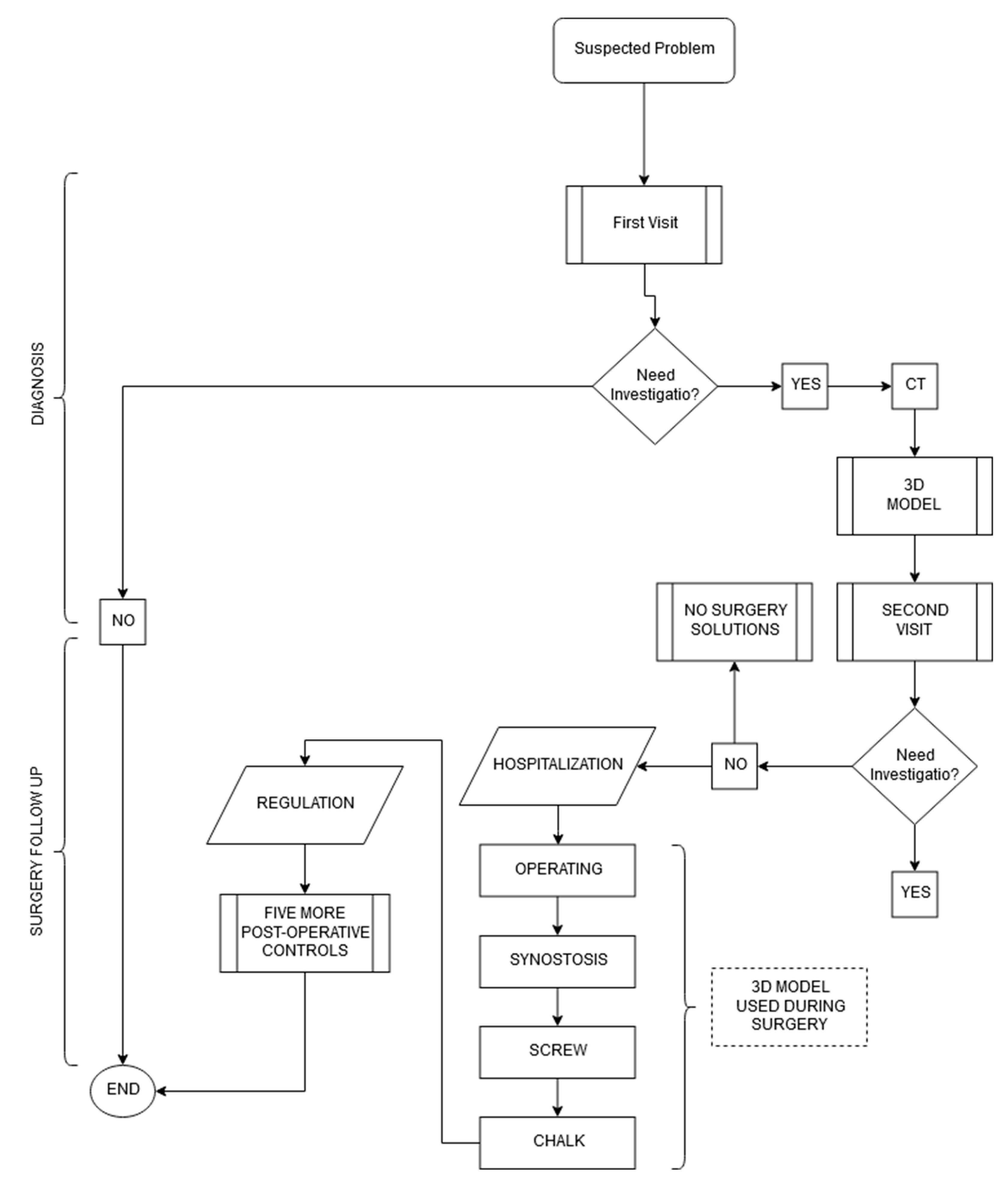
In order to perform this operation a well-established algorithm of diagnosis and treatment was introduced in our department (
Figure 3).
The main diagnostic procedure applied to confirm tarsal coalitions are standing foot and ankle radiographs, and Computed Tomography (CT) [
3]. The radiographic imaging techniques use X-ray beams to represent anatomical structures.
X-ray exposure continues to represent a risk factor for the patient. X-rays produce ionizing radiation, a potentially harmful form of radiant energy. It must be emphasized that the risk of developing cancer following exposure to radiation is generally contained and depends on at least two factors:
Dose of the radiation—the risk increases as a function of dose and frequency to which the patient is subjected [
7].
The risk is also greater in young subjects, exactly the ones considered in this paper. Application of the new workflow will decrease the number of X-rays a patient receives.
However, X-rays are limited in the information they provide—they are restricted to bone tissues and lack three-dimensionality. The results of a first-level investigation will not be able to identify a pathology if RX is unable to diagnose the patient’s cause of pain and if 2D images are not clear enough to suggest surgery.
In the case of tarsal coalition [
8], the main exam for diagnosis and choice of ideal treatment, both conservative and surgical, is CT. The patient generally undergoes to second-level investigations.
Unlike the first-level exam, the CT exam produces 360° images of the body; therefore, exposure to X-rays occurs for a longer period.
Radiation exposure from CT acts differently on children and adults. Children are significantly more sensitive to radiation. In patients subjected to multiple CT before the age of 15, major risks of leukemia, brain tumors, and other cancers were found in the decade after the first CT scan; however, the overall risk of cancer due to a single CT scan was shown to be low, approximately one case per 10,000 procedures performed in children.
The obtained tomographic images are studied in order to carry out pre-operative planning; they are essential in defining the precise location and orientation of the cut [
9].
Since tomographic images are derived from an overlap of 2D images, they can be confusing when determining how to proceed with the correct cut of the coalition. They can also make it difficult to ascertain how thick the coalition to be resected is to avoid injury to nearby bones and joints close to the bony bridge.
Considering what was said about exposure to X-rays, the benefit to find a method that optimizes these first phases, both in terms of minimizing the number of radiological examinations and making the tools used in the preoperative planning more efficient, is obvious.
Furthermore, from an economic standpoint, for every less RX procedure, the saving is around €22; this increases to €87 in the case of CT.
Table 1 presents an overview of the costs and risks of the various procedures that make up the first diagnostic phase [
10].
2.2. Surgical Operation
Once the phase of diagnosis is over, we proceed to the surgical operation [
9,
10]. During preoperative planning, the most widely used methodology to date is CT, but this is not enough to guide the medical team during surgery. For this reason, a fluoroscope is needed in the operating room.
Once again, we use X-rays, this time to try to fill doubts and uncertainties left by the study of only tomographic images. It would, therefore, be appropriate, for the safety of both the patient and the surgeon, to use a technology that enables precision in a manner clear to the anatomy of the malformed foot, thus allowing the surgeon to operate with greater safety, also reducing the period of use of the fluoroscope.
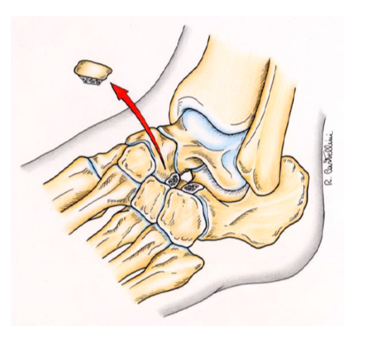
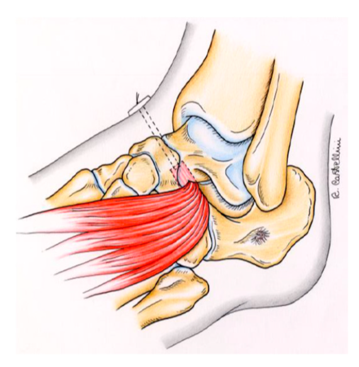
After resection of the coalition, the operation continues as in
Figure 4 and
Figure 5, which show the step of resection of the coalition and that of interposition of the material, respectively. In some cases, the incomplete resection of the coalition may lead to recurrent symptoms, thus requiring further clinical and radiographic assessment and even reoperation. an operation requires a possible surgical revision. The patient will, therefore, have to undergo an operation very similar to the main one, or a further CT scan.
The costs have also been summarized for this phase (
Table 2), which involves the various procedures performed. As can be seen in the table, the duration of an intervention of this type is approximately 60 minutes and costs around €4050.
2.3. Post-Operative Stage
For a correct post-operative course, a sequence of five orthopedic check-ups are required. These are carried out with a time interval of three months. If after the first four visits, no problems occur, the removal of the screws will take place in the last visit; this is a procedure that requires minor intervention in day surgery. The cost of the post-operative stage is listed in
Table 3.
Table 4 summarizes the traditional methodology, emphasizing the main issues that were identified during analysis of the traditional technique.
3. The New Workflow
3.1. Model Creation
As mentioned in the previous paragraph, the images extrapolated from the CT are not always sufficiently clear to allow the surgeon to elaborate in detail the procedure to be performed before the operation. According to the new workflow, a 3D model [
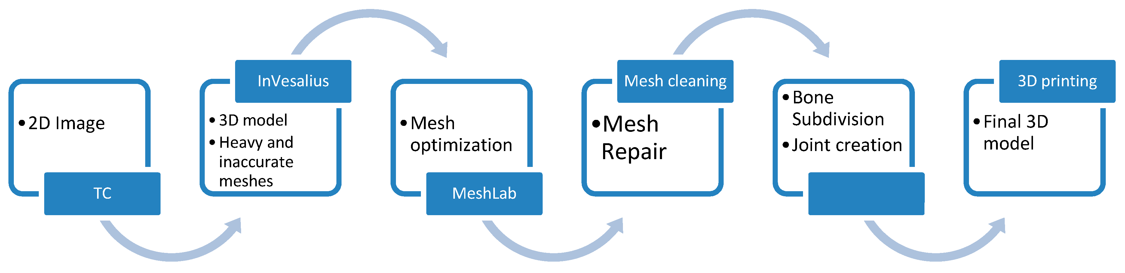
11] should be produced from the CT scan. This model may be used during the study phases of the operation and/or during the surgical operation itself. The primary goal, thanks to the three-dimensional anatomical reproduction, is the reduction of the duration of the surgical procedure, with consequent reduction of anesthesiologic times and surgical wounds. Moreover, the use of fluoroscope in the operating room should also decrease. The process can be subdivided into six consecutive steps (
Figure 6).
3.2. From CT to 3D
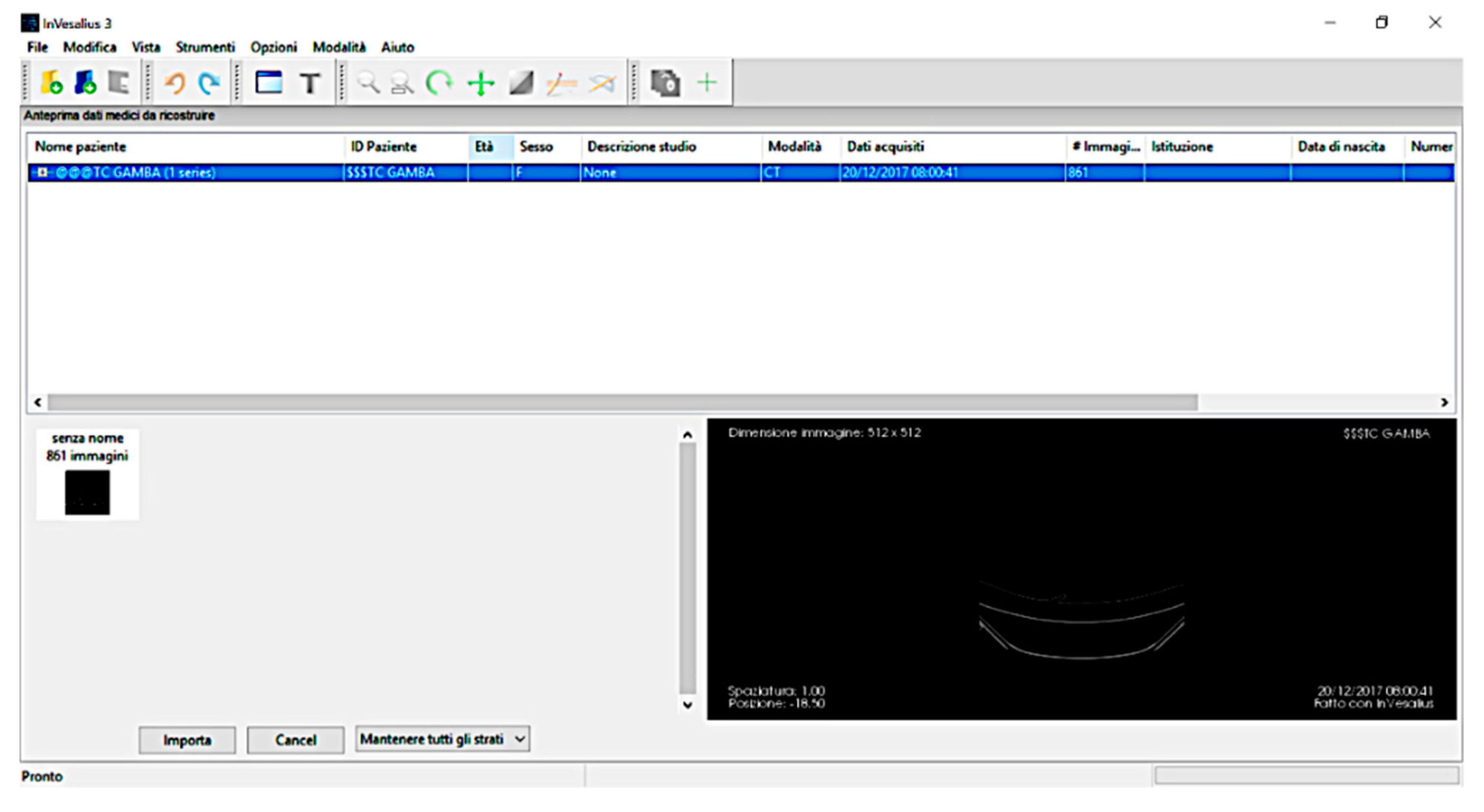
The methodology proposed in this paper uses tomographic images as a starting point for the generation of a three-dimensional model [
12]. Using this technique, the density of tissues crossed by X-rays is converted into different gray levels. The program InVesalius was chosen for this purpose as it is a free medical software able to generate virtual reconstructions of structures of the human body based on CT scans. The first operation to be performed in InVesalius used a DICOM format file (
Figure 7).
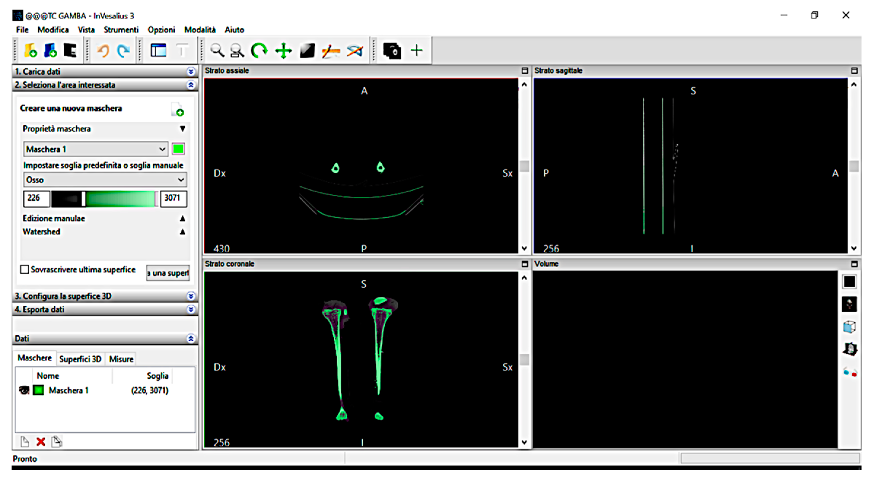
Following the import, the software allows a visualization of the biological structure of interest in the three main axes of the human body (
Figure 8).
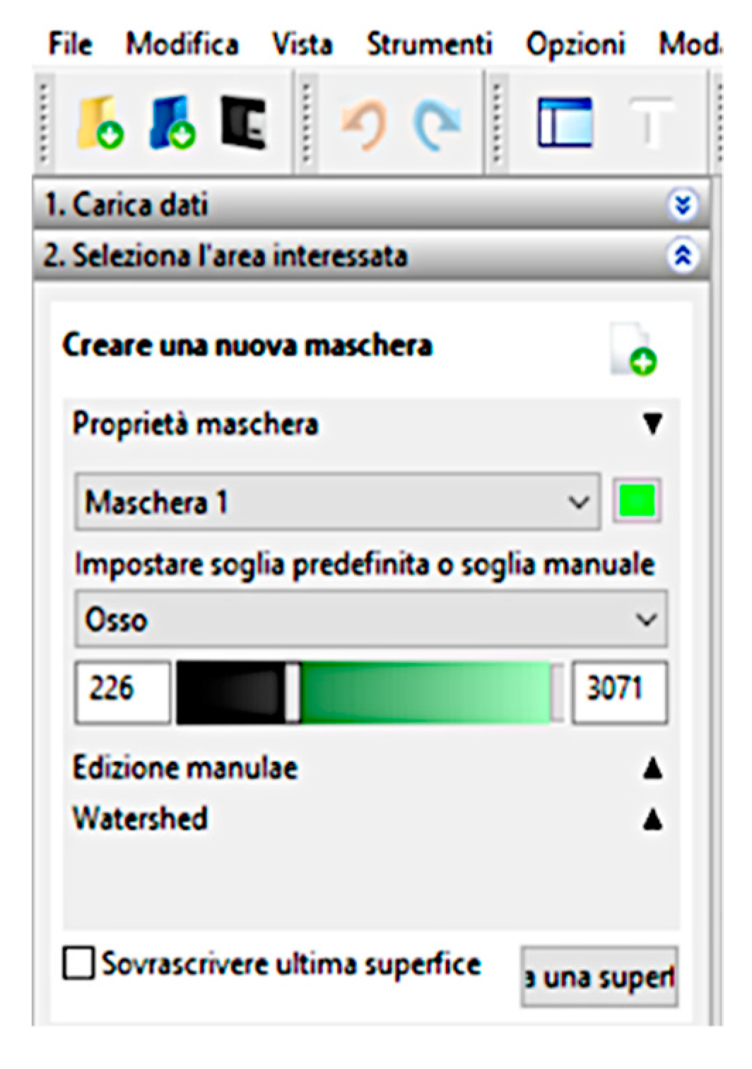
The next step is to segment the image using a colored mask. The mask is nothing but a gray threshold level, comparable to a certain tissue density. By setting the density range, the software highlights a specific region and creates its three-dimensional model, eliminating the rest. There is the possibility of a pre-defined range (for example, compact bone, spongy bone, skin, muscular tissue, etc.) or can be changed manually. After correct identification of the mask, a 3D surface is generated using proper commands (
Figure 9).
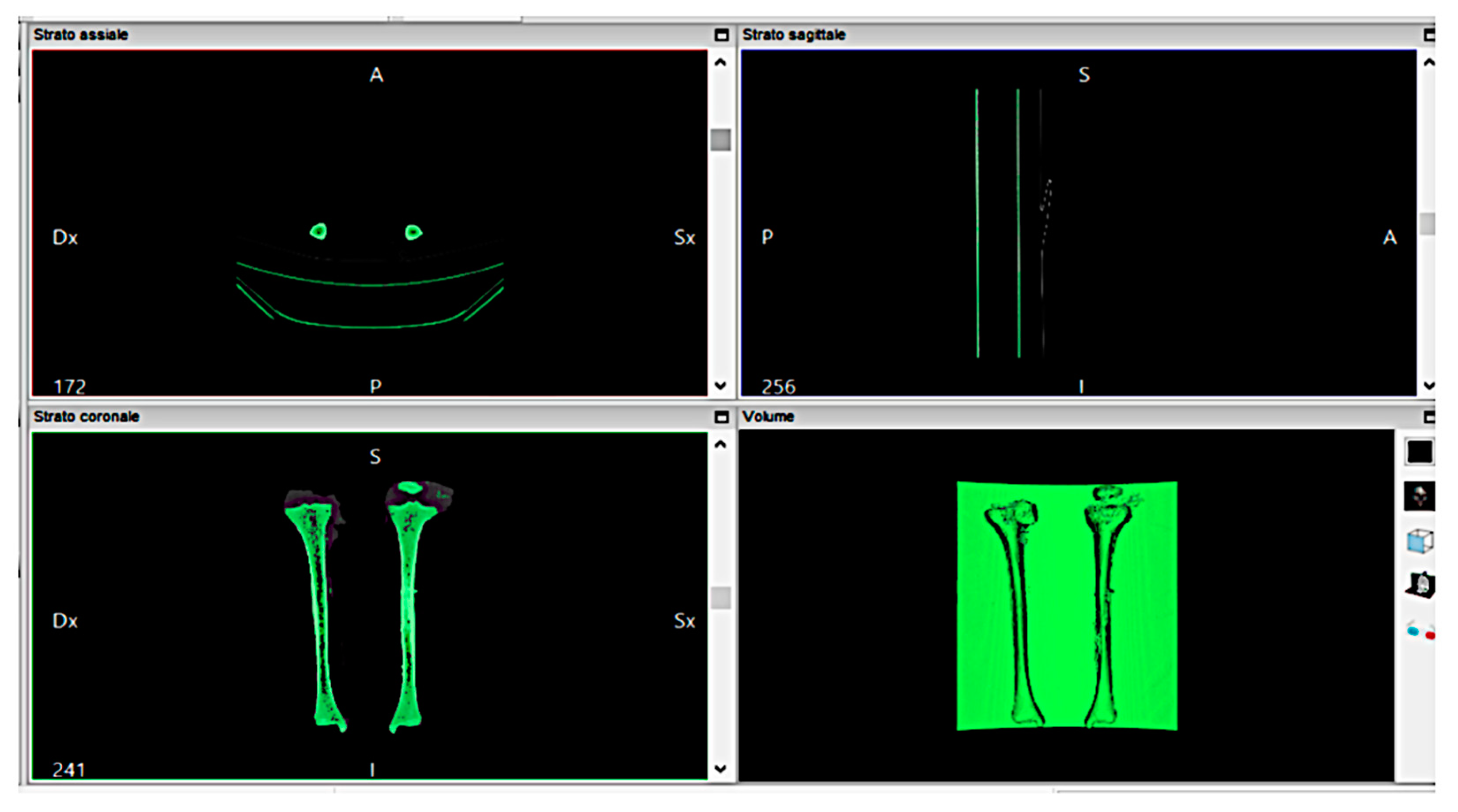
The analyzed case chose to use the “compact bone (adult)” because it had a limited range, avoiding other possible tissue inclusions. When the mask covers the right areas, a three-dimensional surface is created. This is displayed in the lower right window (
Figure 10).
Once the 3D surface is created, it is exported in STL (Stereolithography) format for further modifications. Generally, a mesh created by InVesalius is coarse and not homogeneous; thus, it needs an optimization process. The model’s scale is 1:1, i.e., the process is done using a natural dimensioned model.
3.3. The Optimization Process
There are several limits to the 3D printing of anatomical structures. The first concerns the optimization of the CAD model that is derived from the InVesalius process. The model is too heavy, computationally speaking, and is characterized by a thick structure that must be optimized, thus reducing the inner material. Second, the printed model is not exactly like the real one in the final structure of the bone. In fact, the real density of the bone is variable; instead, the density of the prototype is constant. In the future, an interesting research path would be, for example, to print bones with variable density inside, simulating the real structure of the bone. The third limit is about the exterior shape, and the present paragraph is about its optimization.
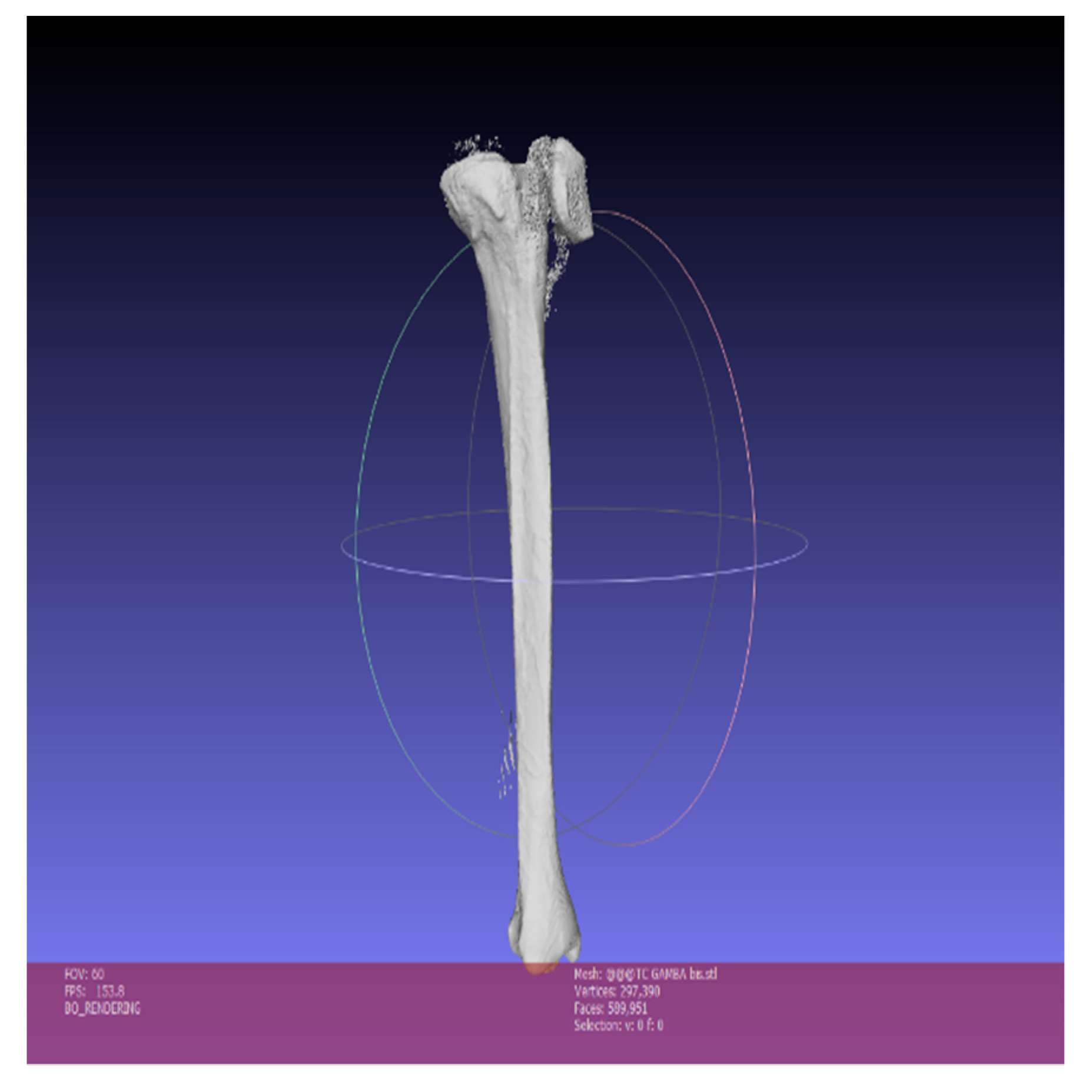
For shape optimization, we used MeshLab.
Figure 11 only shows the tibia. The inaccuracies and irregularities mentioned above are clear here, especially in the upper part of the bone, near the knee. Furthermore, in the lower part of the image, there is an indication relative to the number of faces that make the 3D surface (589,951).
To reduce the number of triangles that compose the mesh, it is important to eliminate vertices and faces included in the inner cavity of the model. These are useless for the purpose of 3D printing. Their elimination simplifies the geometry, making the 3D-printing phase faster and more effective.
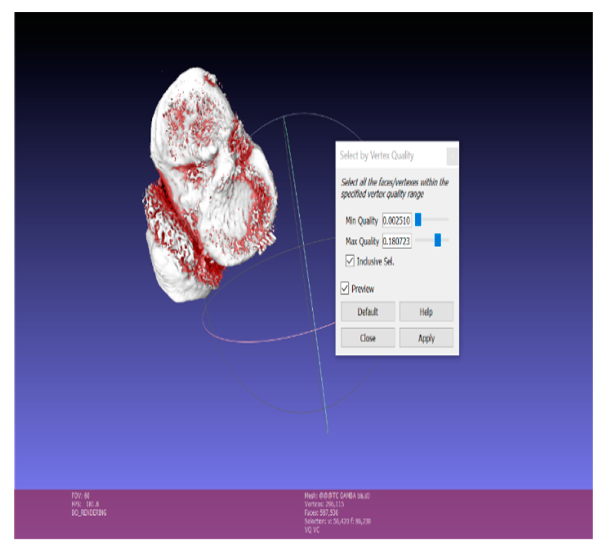
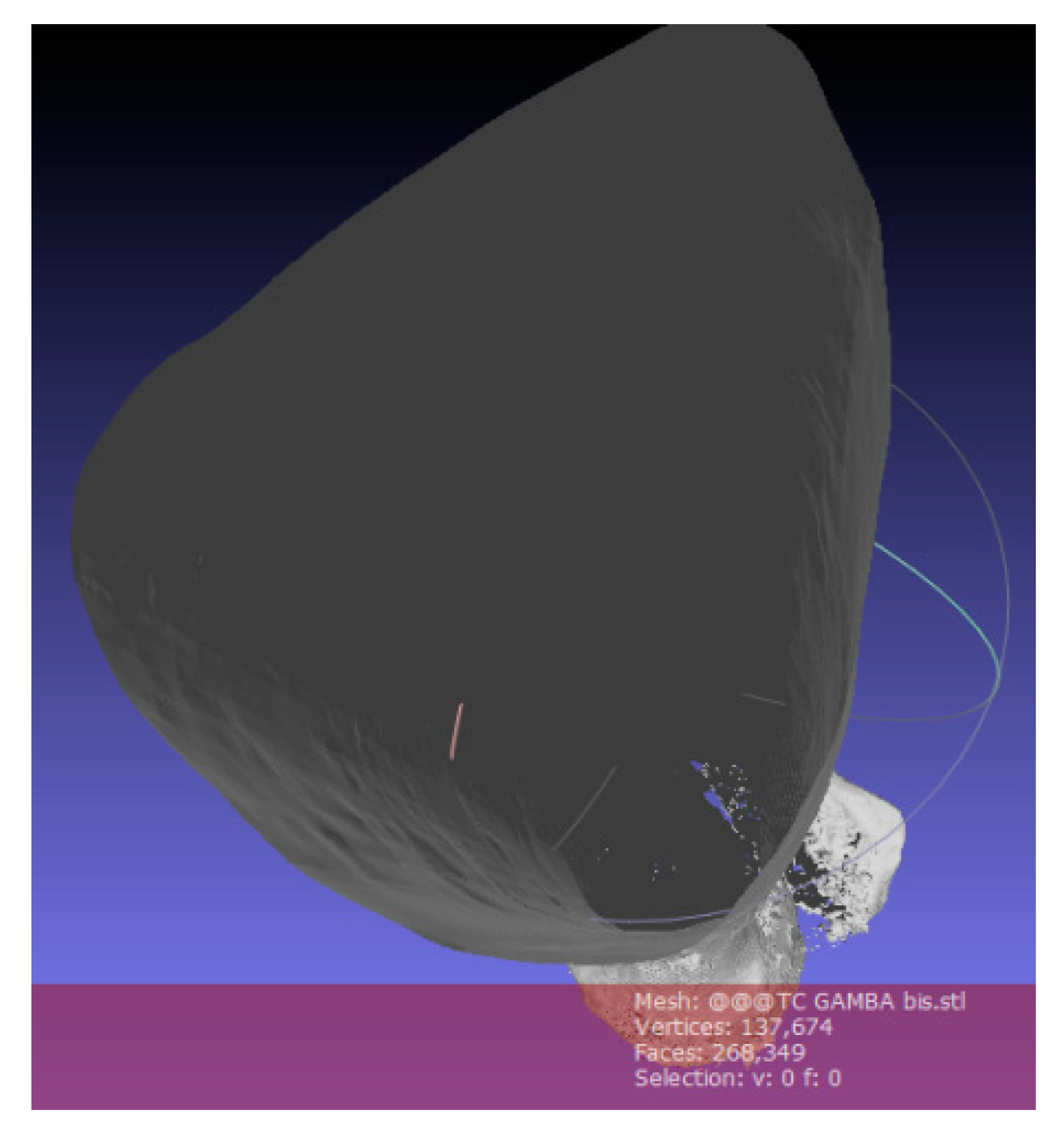
The Ambient Occlusion filter is then applied, highlighting visible parts. This function simulates a global diffuse illumination and colors the faces of the mesh according to a gray scale, based on how much the single polygon is exposed to illumination. We then proceed to selecting the bone’s inner material (highlighted in red in
Figure 12).
Figure 13 shows the empty bone interior and the number of faces from which the optimized model is composed: 268,349. Moreover, small and isolated surfaces need to be eliminated; this is done using the Small Components function. This filter helps choose a ratio below which surfaces should be deleted (
Figure 14).
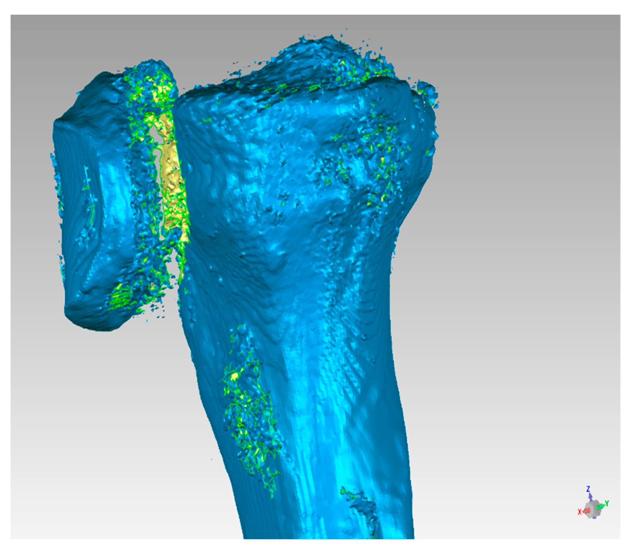
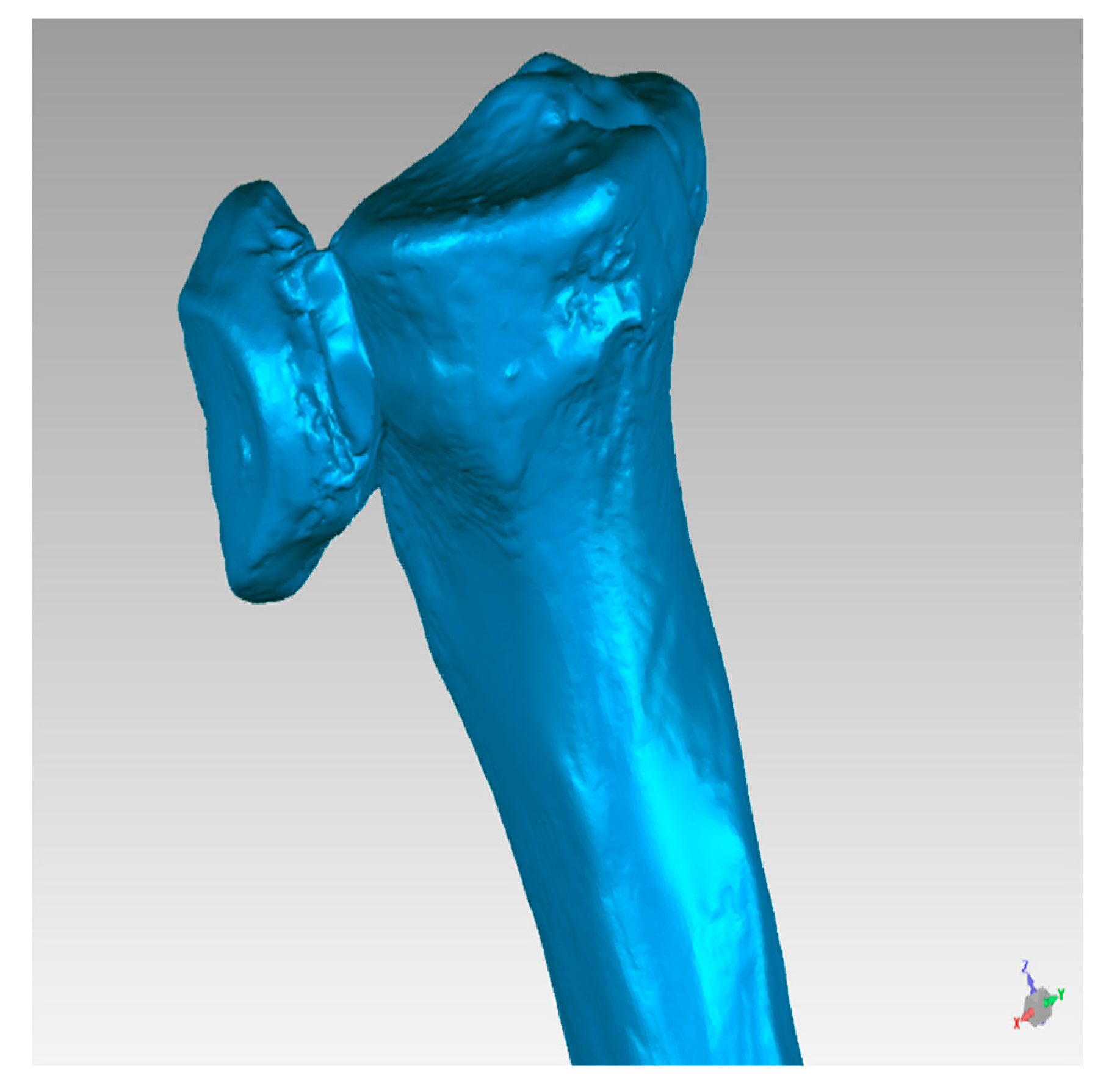
At the end of the optimization process, mesh irregularities, such as duplicate triangles, non- manifold edges, non-manifold vertices, orientation problems (the triangles are not oriented in the same direction), and disconnected zones (the mesh is composed of several disconnected zones) are removed and the resulting clean surface is used in the 3D printing process (
Figure 14 and
Figure 15).
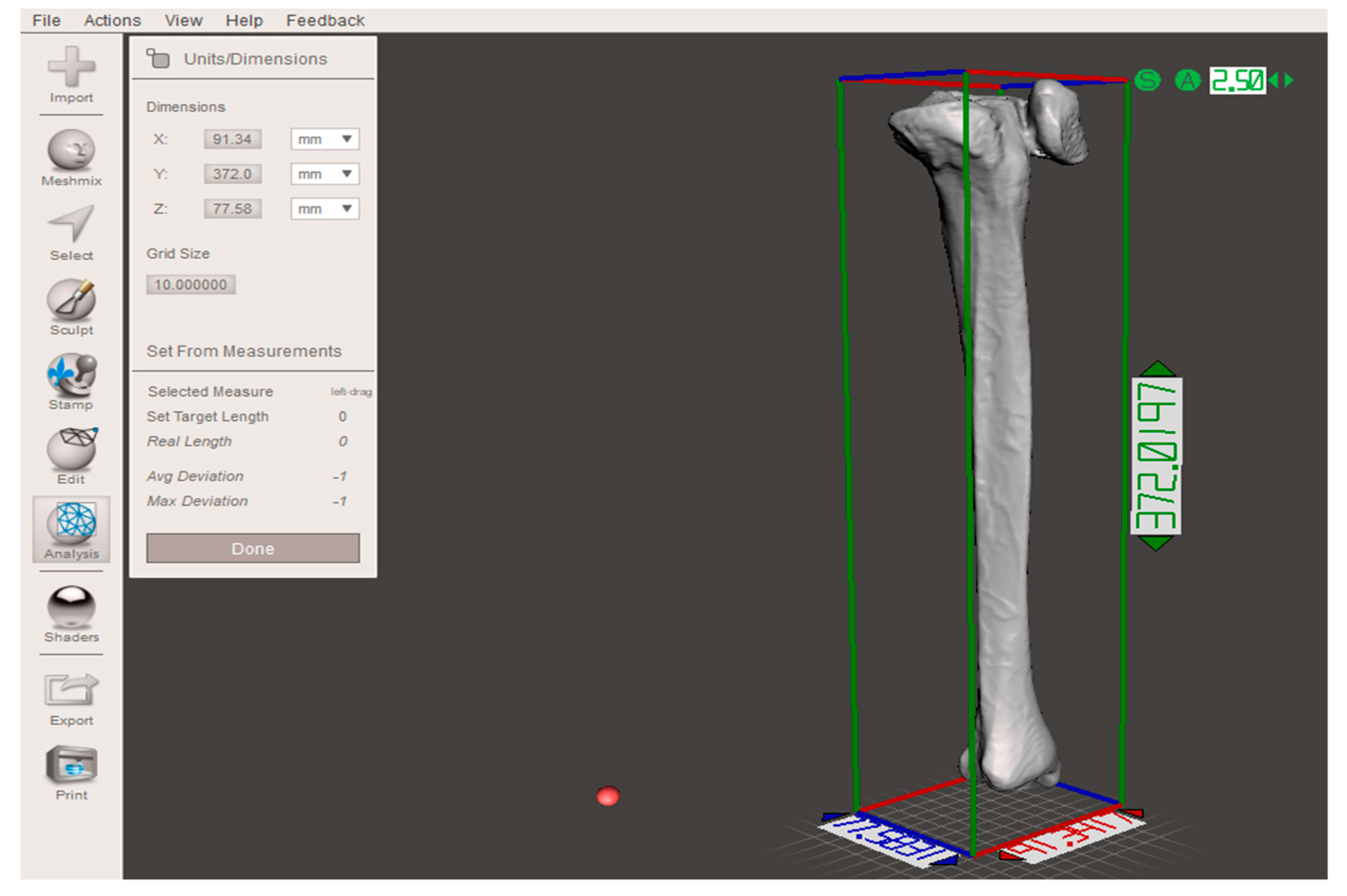
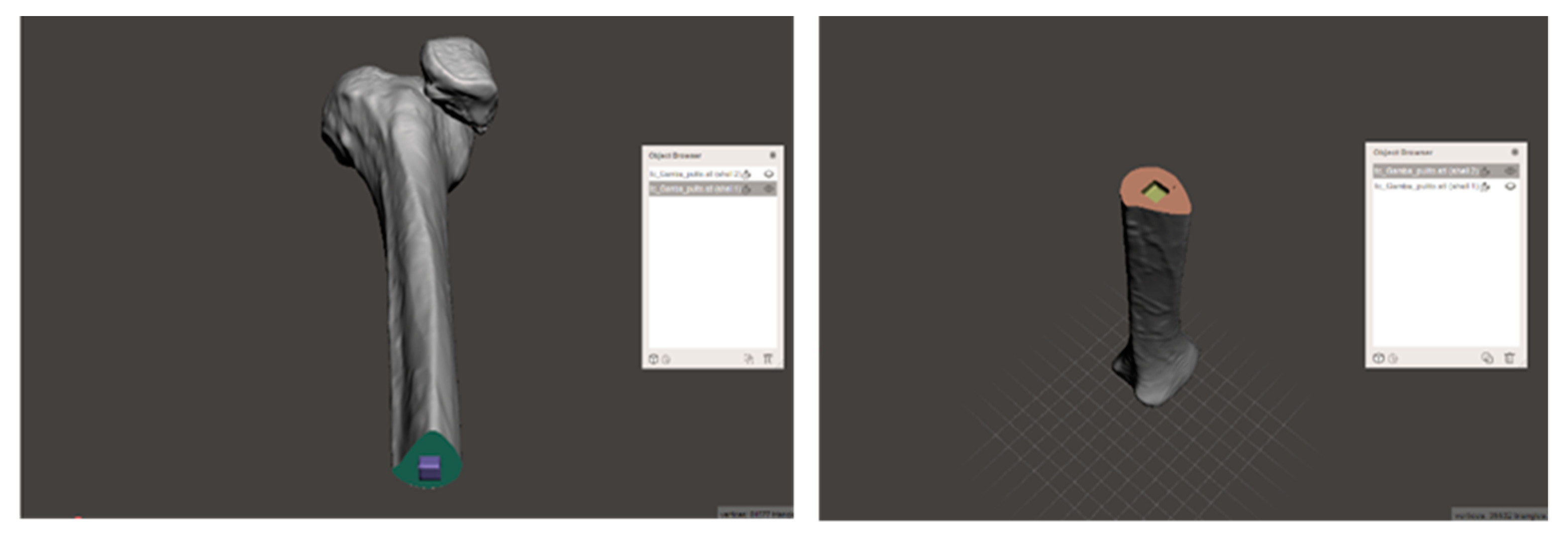
Because of the dimensions of this particular bone (X = 91.34 mm, Y = 372 mm, and Z = 77.58 mm;
Figure 16), MeshMixer is used to separate the geometry into two parts and generate a connection pin (
Figure 17).
The 3D printer used for this application is EZT3D Delta, which uses Fused Deposition Modeling (FDM) technology [
13,
14]. This printer is a low budget 3D printer and it can be assembled by the user. It is made by an aluminum frame, an Arduino board and an extruder section. Each component can be easily changed or customized.
Table 5 shows a material cost analysis, carried out on the basis of the current market price of the specific material per kg. Moreover, autoclavability was considered despite the cost, because of this particular medical application.
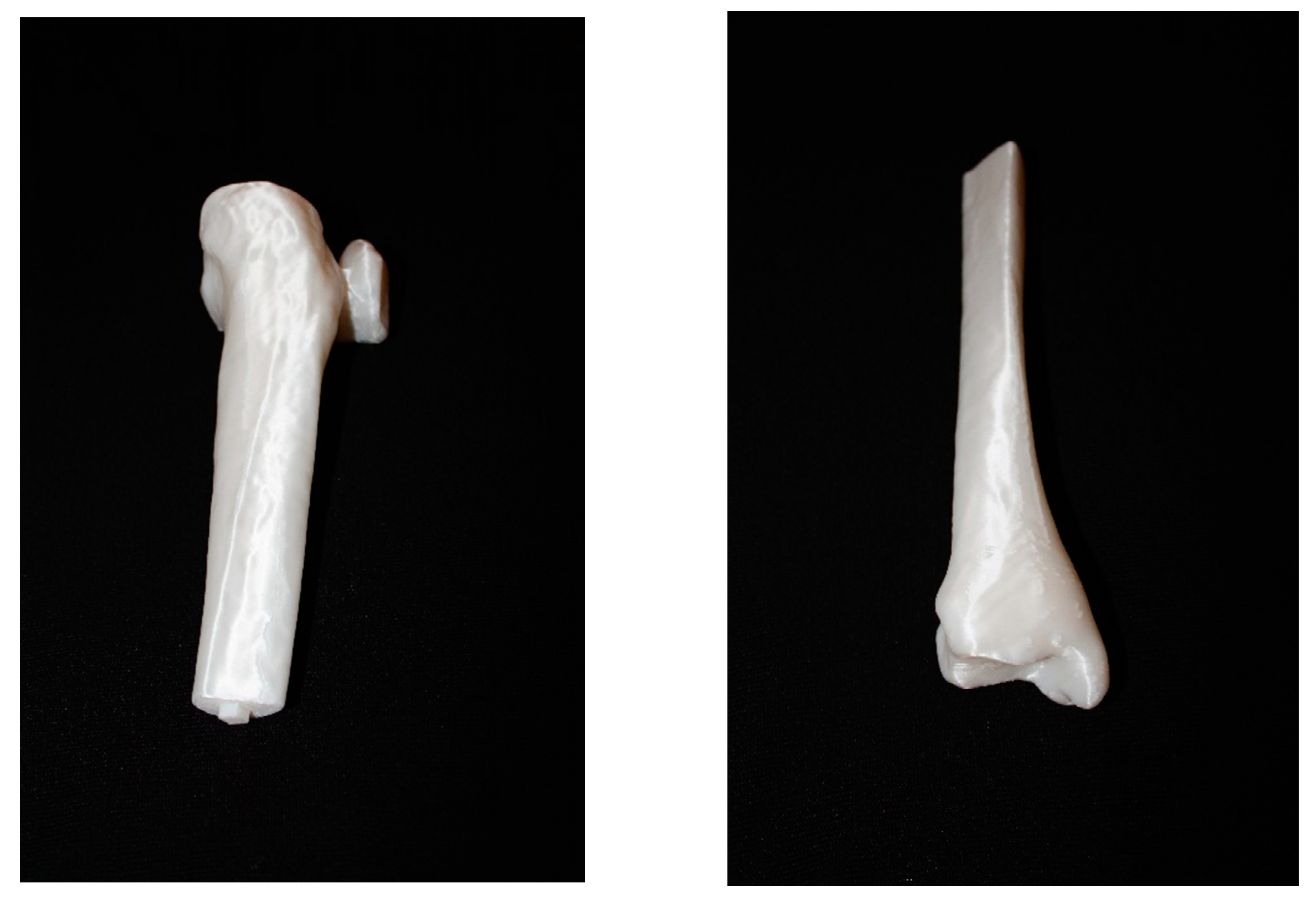
Finally, the studied methodology helped obtain a three-dimensional bone model in PLA, which perfectly fits the anatomical structure of the CT images (
Figure 18).
4. Cost Analysis
The realization of the three-dimensional model involves a series of costs:
The costs relative to this specific printed model are summarized in
Table 6. The printer costs about 220 € and has a working life of approximately 2000 working hours. The labor time required for conversion and cleaning of the model is four hours on an average, and the estimated cost of a specialized operator is 20 €/h. For printing of the model, an average of 0.25 kg of material is necessary. The actual printing takes 22 h. The software used is open source and does not add to the costs.
5. The Innovative Workflow
For the survey, we used data from a pilot study, “3D-printing models in the pre-operative planning of the pediatric patient suffering from congenital malformations”.
3D printing enables surgeons to understand the anatomical condition of the patient better. This further results in the development of more detailed surgical plans, better results, more safety, and better speed during the operation. The possibilities to refer to the prototype, both before and during the intervention, should enable only minor use of the fluoroscope. Controls are still performed in the post-operative stage because they are necessary to ensure that the patient is responding well to the operation.
The new workflow is illustrated in
Figure 19. It was observed that the duration of intervention is reduced by using a prototype during surgical planning. This enables the use of a lower anesthetic dose, and subsequent lower risk of infection. The use of 3D models in the pre-operative phase lets surgeons proceed with more confidence during surgery due to the increased knowledge of the anatomy of that specific case. One of the main advantages of this new method is reduction in exposure to radiation. With the new procedure, the first RX scan is no longer necessary, and the use of fluoroscopy can be reduced. In addition, the patient can understand how their procedure will take place by simulation on the prototype. All of this has a positive impact on the hospital, as it guarantees an improvement in service for both patients and hospital staff. There is also a decrease in direct costs.
Table 7 shows that problems of the traditional method are now solved with the introduction of the three-dimensional anatomical model.
However, even the most innovative procedure is not without limitations. The most obvious is the difficulty in organizing all the steps in the workflow. The conversion of tomographic images to an STL file should be performed as soon as possible and sent directly to the 3D printer.
Another weakness is correct creation of the three-dimensional surface. The modification of the mesh is carried out manually and the operator should have both engineering and medical skills. If this is not met, model inaccuracy can occur, rending it useless. Mesh cleaning in particular is the riskiest step, since it requires a high awareness of bone anatomy and patient pathology to guarantee a correct 3D surface.
6. Innovative Procedure Profits
A three-dimensional reproduction with the new workflow helps reduce costs. In the diagnostic phase, the number of orthopedic visits fell from 3 to 2 for each patient, a decrease by 33.4% or saving of €18 per patient.
Moreover, the 3D model allows to bypass the first radiological step, so the number of radiological visits per patient is halved, avoiding an expense of €21 per patient.
The traditional surgical intervention takes about 60 minutes on an average. Using the prototype, this should be reduced by 15 minutes (25% less). This reduction in use of the operating room costs €206.75 less per patient.
Finally, studying of the 3D prototype decreases recurrence rate by 15%, when compared to the traditional case (only CT used). Moreover, with this innovative methodology, there is one less case of relapse in a year (2 cases compared to 3 in the traditional procedure). In a worst-case scenario, if all 2 recidivist patients need re-intervention, total saving is still about €5094.32 (new TC: €86.5; inspection visit: €18; surgery: €3380; post-operative phase: €1627.32).
Table 8 summarizes the improvement rates of the new workflow in terms of money saved per year.
The cost savings in the diagnosis phase is €1295.4 per year, in the surgery phase it is €10,258.5 per year, and in the post-operative phase it is €1952.8 per year—a total saving of €13,526.7 per year. This amounts to total reduction in spending of 7.8% per year.
It is also necessary to consider the cost of creating a sterilizable prototype, i.e €107.42 per model, since the only suitable one from the above-mentioned list is HT-PLA. Considering that the number of 3D models in one year is on average 27 (25 new cases and 2 repeat offenders), the total cost is approximately €2900 per year.
The final cost of the innovative method is, therefore, around €10607 per year, which offers annual savings of 6.1%.
The result obtained is based on the worst-case scenario, where re-surgery is necessary.
Table 9 also considers the case of zero recidivism for both procedures.
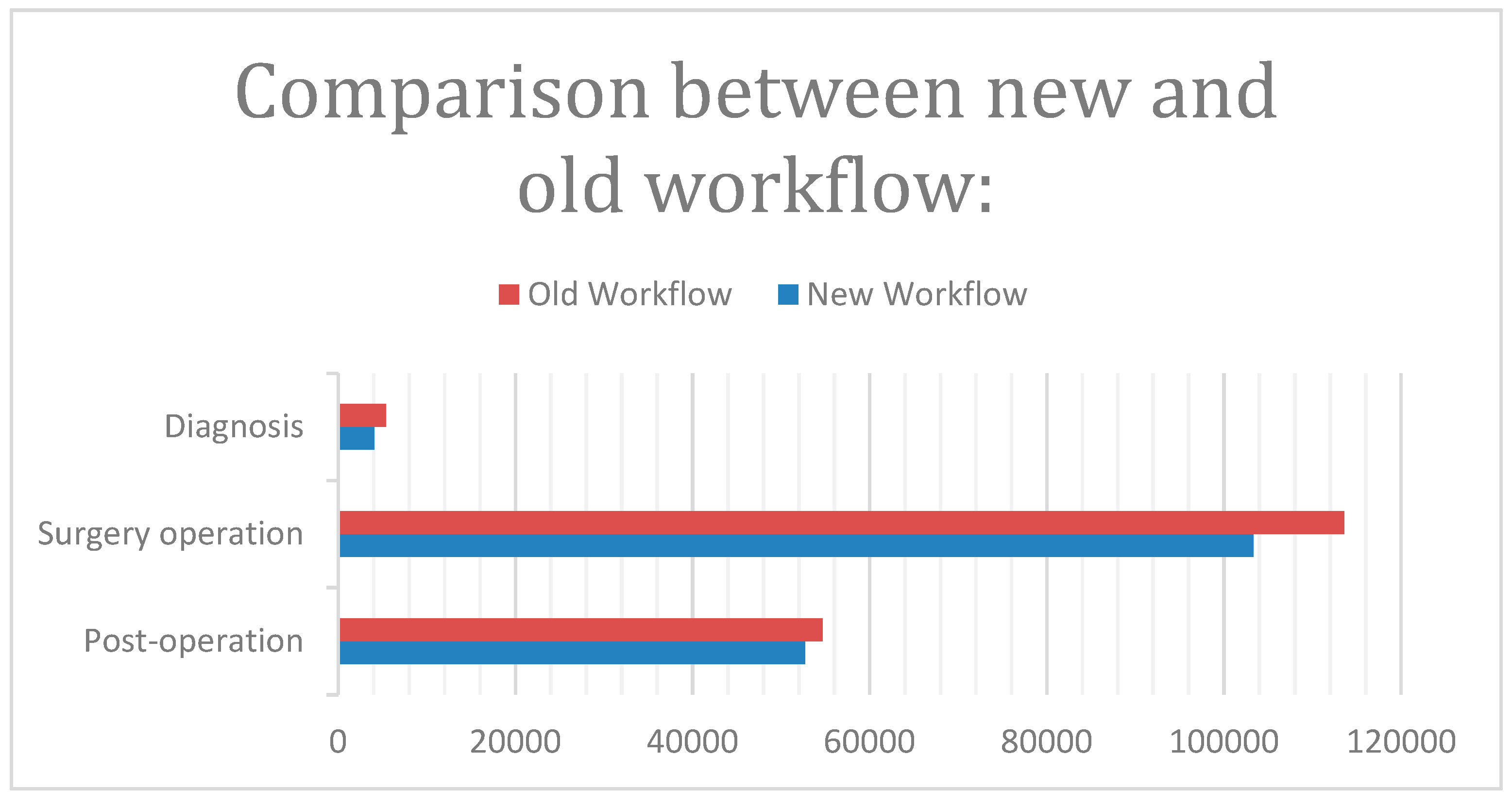
Taking into account the fact that the production cost of 25 prototypes is €2686, the total cost of the proposed procedure is €1,02,943 per year. The advantages offered by the use of the prototype make the innovative procedure more tempting (
Figure 20).
7. S.W.O.T. Analysis
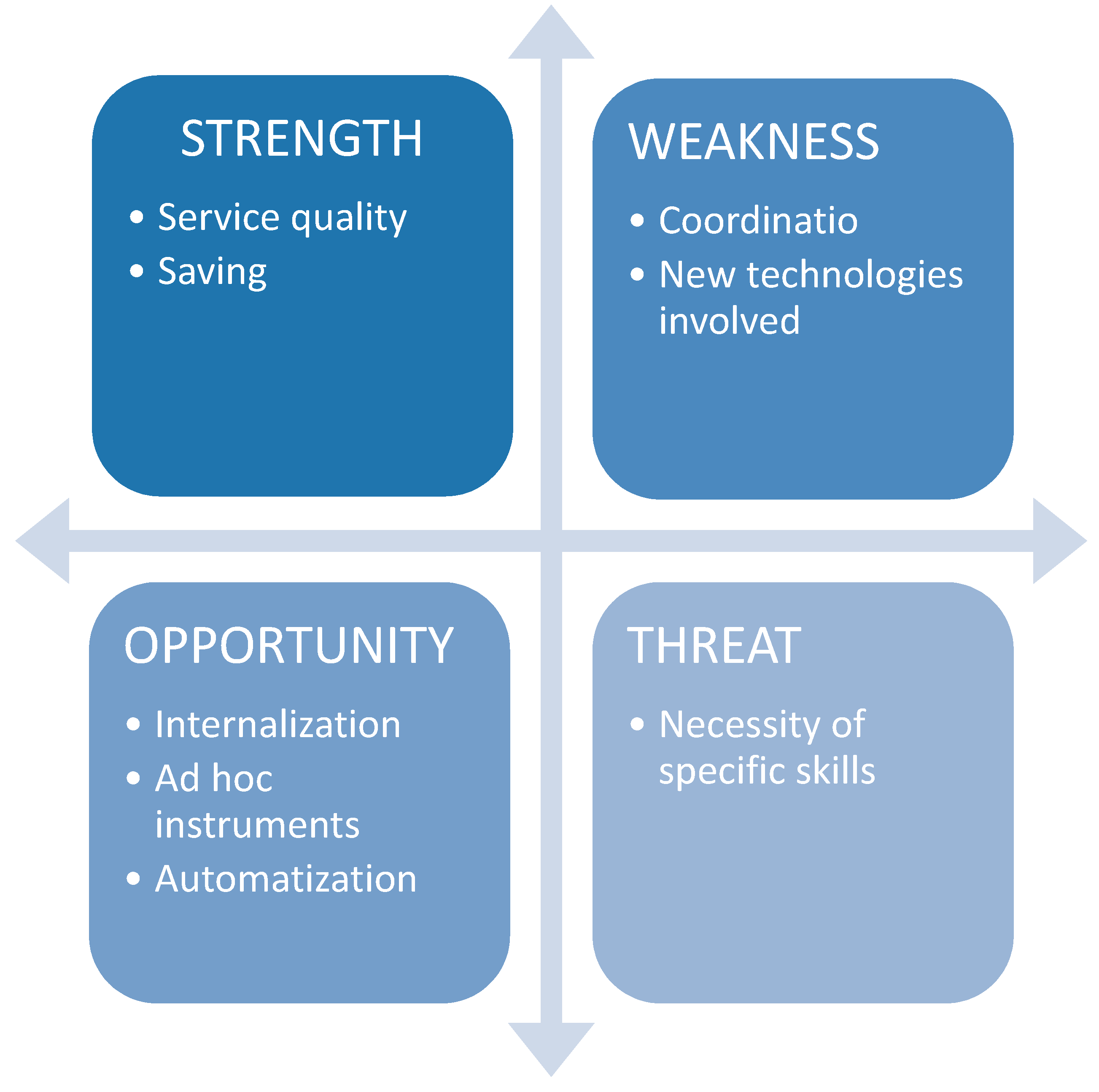
A SWOT analysis was carried out as shown in
Figure 21:
Strengths: When we generally talk about innovative technologies, we expect high costs for realization and/or use. However, in this paper, the proposed 3D printing method not only covers production costs, but also saves money, when compared to expenses foreseen by the traditional procedure. This is possible because of a reduction in time taken for certain activities, such as surgery, as well as a lesser cost of model realization.
The improved quality of the procedure has a strong impact on both the patient and the doctor. The former sees a reduction in the number of visits, achieves greater awareness of their surgery, and has lesser exposure to X-rays. The latter tests the procedure on the prototype and clearly defines the surgical plan, thus improving surgical outcomes.
Weakness: Coordination between the doctor and the mechanical engineer can be a weak point. Proper collaboration is, thus, needed for the success of the prototype and to avoid inconsistencies in the actual anatomy of the reproduced bone. An optimal solution would be to entrust the realization of the model to professionals that are well-versed in both the medical and engineering fields. If this role is handled by two experts, they should work in proximity with each other to simplify communication and resolve uncertainties that arise in the 3D surface cleaning phase.
In addition, the introduction of the proposed 3D model in the medical workflow requires a higher awareness of 3D printers and printing materials, in order to choose the most suitable combinations.
Threat: Surgeons, radiologists, and engineers must develop new skills and assume new roles. Without specific training on specific software and hardware, there is the risk of incorrect implementation, subsequently leading to higher costs and stretched timelines.
Opportunity: Internalization of the prototype realization procedure offers a great opportunity. Coordination is fundamental for success of the procedure; its smooth merging in the system could improve the workflow.
The 3D printing process help in the realization of patient-specific instruments (PSI) involving the use of CT for “rapid prototyping” methods. A specific cutting guide could also be a possible implementation of PSI. Custom tools can both increase operating accuracy and reduce operating times.
8. Conclusions
The traditional methodology has certain limitations. The first is inaccuracy of the techniques used for diagnosis. This has prompted a desire to provide surgeons with tools that allow better understanding of the difficulties related to the anatomy of each individual case. The proposed tool is a three-dimensional model that can be used in the planning phase.
The use of various software was able to achieve reproduction of a bone in HT-PLA that perfectly reflects the anatomical structure shown in the TC images. The economic impact of the introduction of this technology into the traditional workflow was also studied. The production costs currently required for an autoclavable model are approximately €110 per model.
On the other hand, a comparison of the procedure currently in use and the proposed one show considerable advantages for both the patient and the doctor. The patient has a better understanding of their clinical situation and is offered less-invasive surgical treatment. The doctor benefits from a better visualization of the problem, thanks to better surgery planning in the pre-operative stage. The hospital, too, has lower direct costs and reduced risks of complications and infections.
This study found that direct costs were clearly reduced on using the 3D model, specifically owing to a decrease in intervention time and recurrence rates.
Considering both the economic savings and the additional costs necessary for the 3D model, it was concluded that the innovative method is clearly convenient from a practical and economic point of view.
However, it is important to note that this research focused on a limited number of patients, it should be reproduced many times with a higher number of patients as shown for other methodologies in [
15,
16].
Possible future developments have also been identified to extend the use of 3D printing in orthopedics to improve the operative planning of other pathologies as well. An example is the realization of a 3D printing laboratory inside hospitals, managed by subjects specialized in 3D models for medical purposes.

 ,
, 


