1. Introduction
Large-scale urban construction leads to the gradual decrease of available land area. Therefore, many cities have been developing in the underground space. More and more subway tunnels and foundation pit projects have been appearing in urban infrastructure construction. Pile foundation has the advantages of a small settlement and wide application, so it is widely used in urban construction. However, due to the limitations of driving routes and space, special engineering problems are often encountered in subway construction. It is all known that whether the New Austrian Tunnelling Method or shield tunneling method during tunnel construction will inevitably cause the ground stress release of the tunnel surrounding soil and movement of the surrounding soil towards the excavation area, leading to a certain influence on the deformation and internal force of the adjacent pile foundation. In engineering design and construction, how to accurately evaluate the mutual effect of tunnel excavation and the adjacent pile foundation is one of the main difficulties in current research.
On the one hand, research has focused on the influence of tunnel excavation on the deformation and internal force of the passive pile foundation. The passive pile is caused by the deformation or displacement of the soil around the pile due to the action of surface load or stratum unloading, thus passively bearing the pressure from the soil. At present, there are three main methods, namely, the integral finite element method [
1,
2,
3,
4], simplified analytical method [
5,
6,
7] and laboratory test method [
8,
9,
10].
On the other hand, to guarantee the safety and normal operation of tunneling and the nearby existing structures, an effective prediction model for the shape and range of tunneling-induced potential plastic zones adjacent to pile foundations is required. The prediction for the potential plastic zone of tunnel excavation adjacent to existing pile foundations aroused the research enthusiasm of scholars [
11,
12,
13]. To predict the potential plastic zone of a tunnel excavation adjacent to a pile foundation in soils, Xiang and Feng [
11] proposed a prediction method by superimposing the pile foundation loads with the tunneling-induced stresses. However, the proposed method by Xiang and Feng [
11] was restricted to weightless half space (that is, it did not include the gravity field).
In this paper, an analytical approach is initially presented to predict the potential plastic zone induced by tunnel excavation adjacent to an existing pile foundation in a gravity field. The accuracy of the proposed method is then verified by comparisons with one of the existing approaches and numerical simulations. Finally, a parametric analysis is performed to analyze the influences of soil parameters, axisymmetric boundary conditions, and pile parameters on the boundaries of the potential plastic zone.
2. Prediction Model for the Potential Plastic Zone
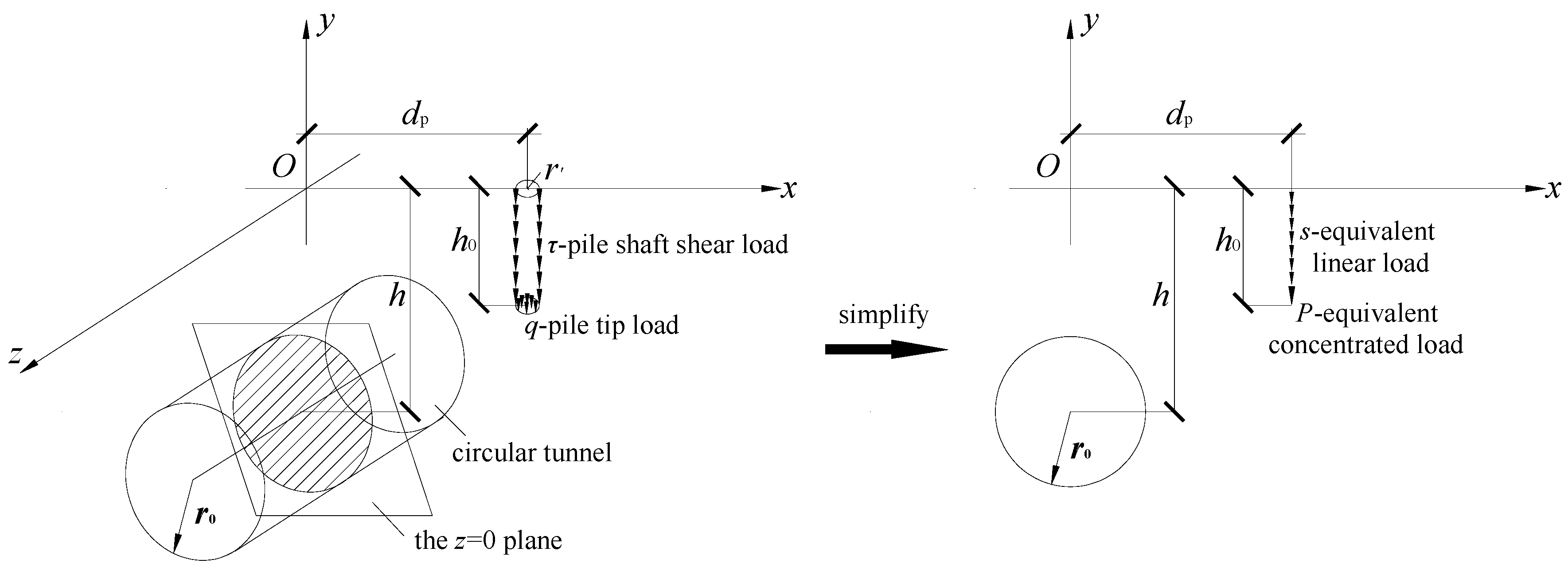
The prediction model for of the potential plastic zone of tunnel excavation adjacent to an existing pile foundation in soils adopted the idea of superposition. Referring to [
11,
12], this practical problem is simplified into the following analytical mechanics model, as shown in
Figure 1.
A similar analytical calculation procedure is adopted in this paper to obtain the potential plastic zone induced by tunnel excavation adjacent to a pile foundation in a gravity field.
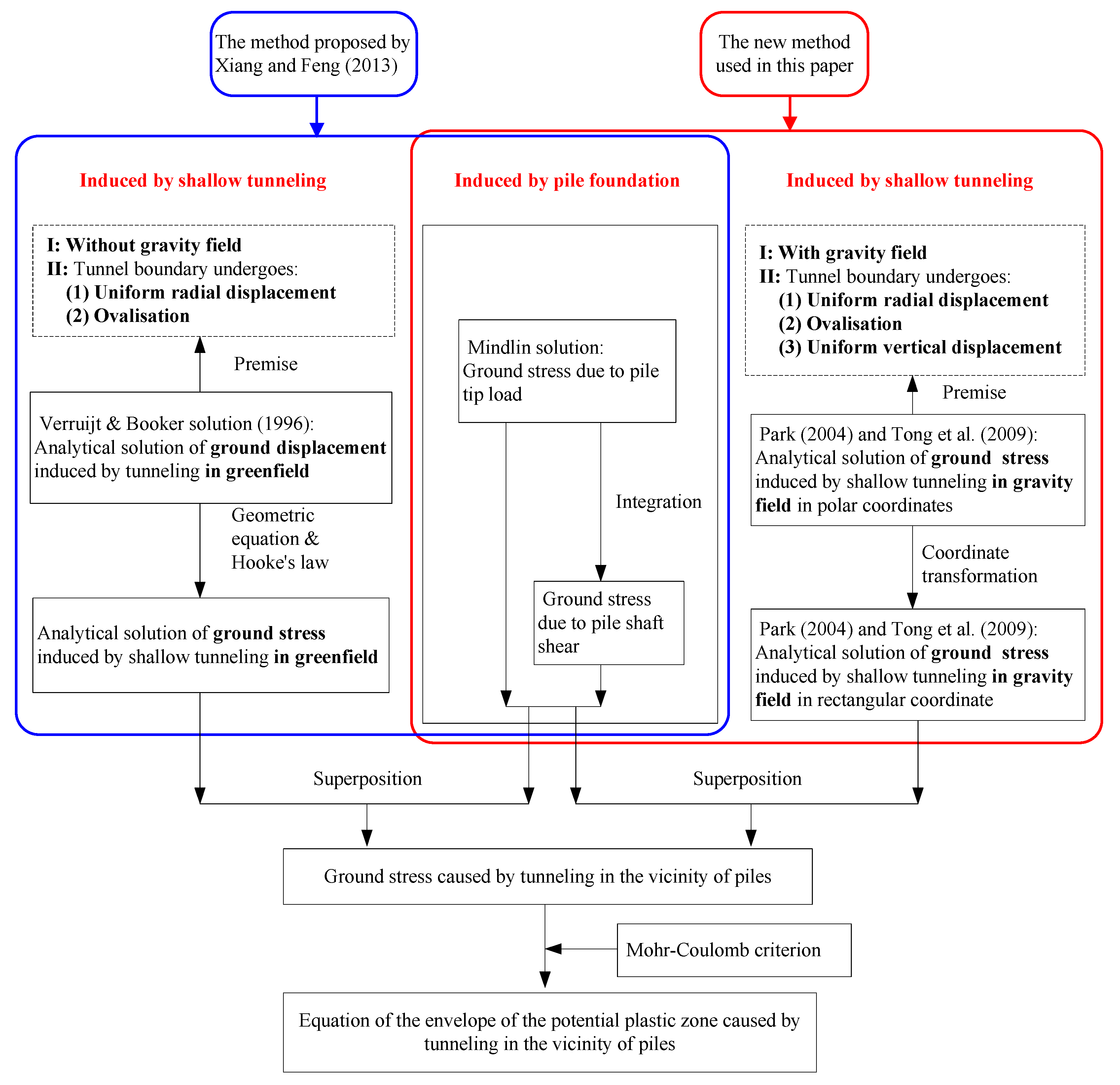
Figure 2 shows the comparison of the calculation procedure in this paper and that in [
11].
The calculations of ground stresses induced by pile foundation loads adopt the Mindlin’s solution [
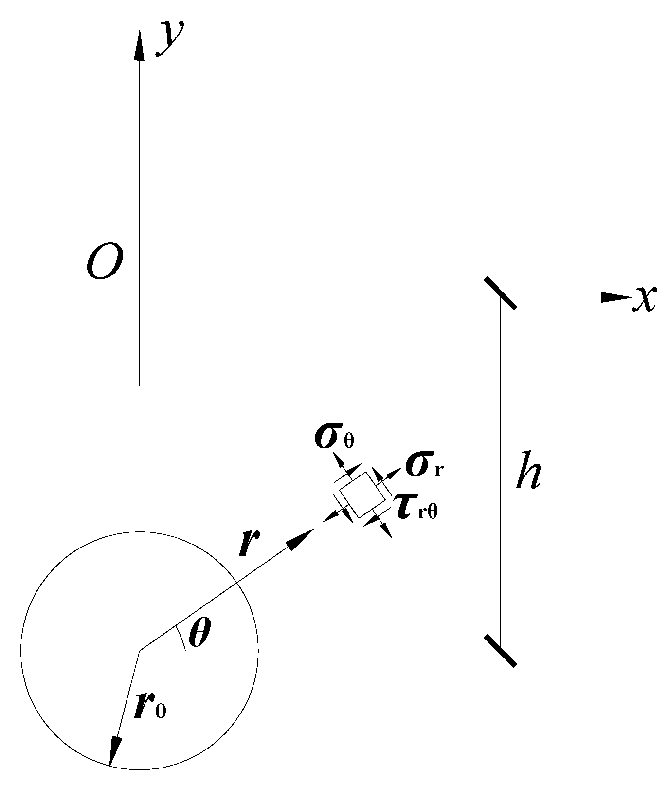
14] in both analytical calculation procedures. The calculation of ground stresses due to tunnel excavation adopts the analytical solutions of ground stresses in a gravity field (Park [
15], as shown in
Figure 3), whereas the calculation of ground stresses (Xiang and Feng [
11]) adopts the analytical solutions of ground stresses without considering the gravity field. Moreover, complex boundary conditions (Pinto and Whittle [
16] and Tong et al. [
17], as shown in
Figure 4) are used in this paper as the tunnel boundary conditions instead of the boundary conditions used by Xiang and Feng [
11].
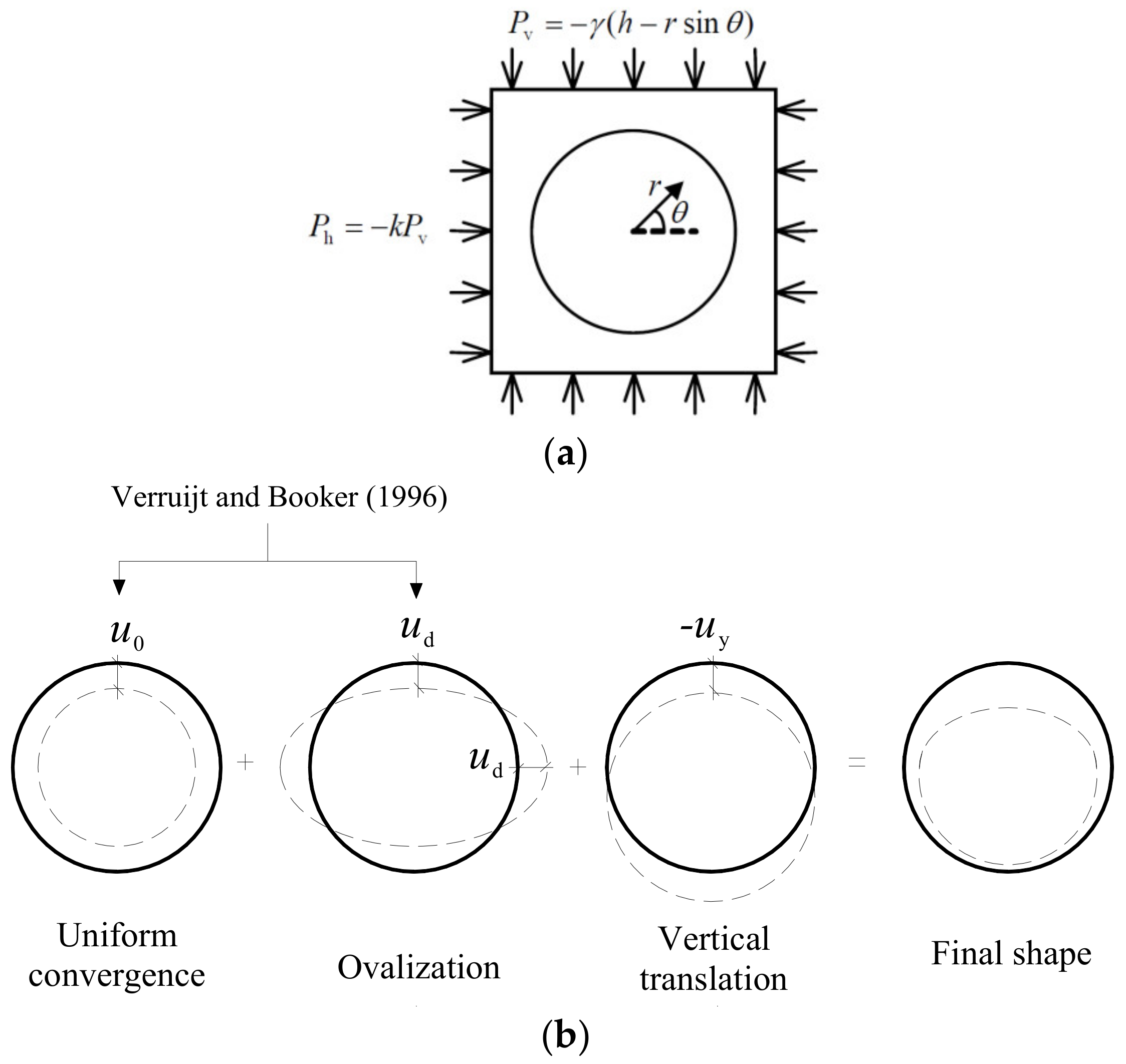
By replacing the tunnel boundary conditions adopted by Park [
15] with boundary conditions summarized by Pinto and Whittle [
16] and Tong et al. [
17], the following boundary conditions apply, as shown in
Figure 4:
Referring to Park [
15] and considering the coordinate system transformation, the solutions of ground stresses induced by shallow tunneling in a gravity field can be easily obtained as follows:
where
To transform the stresses under polar coordinates into stresses under Cartesian coordinates, the following equations are adopted:
The superscript ST means that the ground stresses are induced by tunnel excavation.
Based on the Mohr–Coulomb yield criterion, an implicit equation of the boundaries of the potential plastic zone induced by tunnel excavation adjacent to a pile foundation in a gravity field in the
x-
y plane (
z = 0) can be obtained according to the new superposition method in
Figure 2.
3. Comparison and Validation
Based on the approach presented above, the boundaries of the potential plastic zones induced by tunnel excavation adjacent to the pile foundation were drawn by using the software MATLAB. Referring to Xiang and Feng [
11], the parameters used in the calculations were assumed as shown in
Table 1.
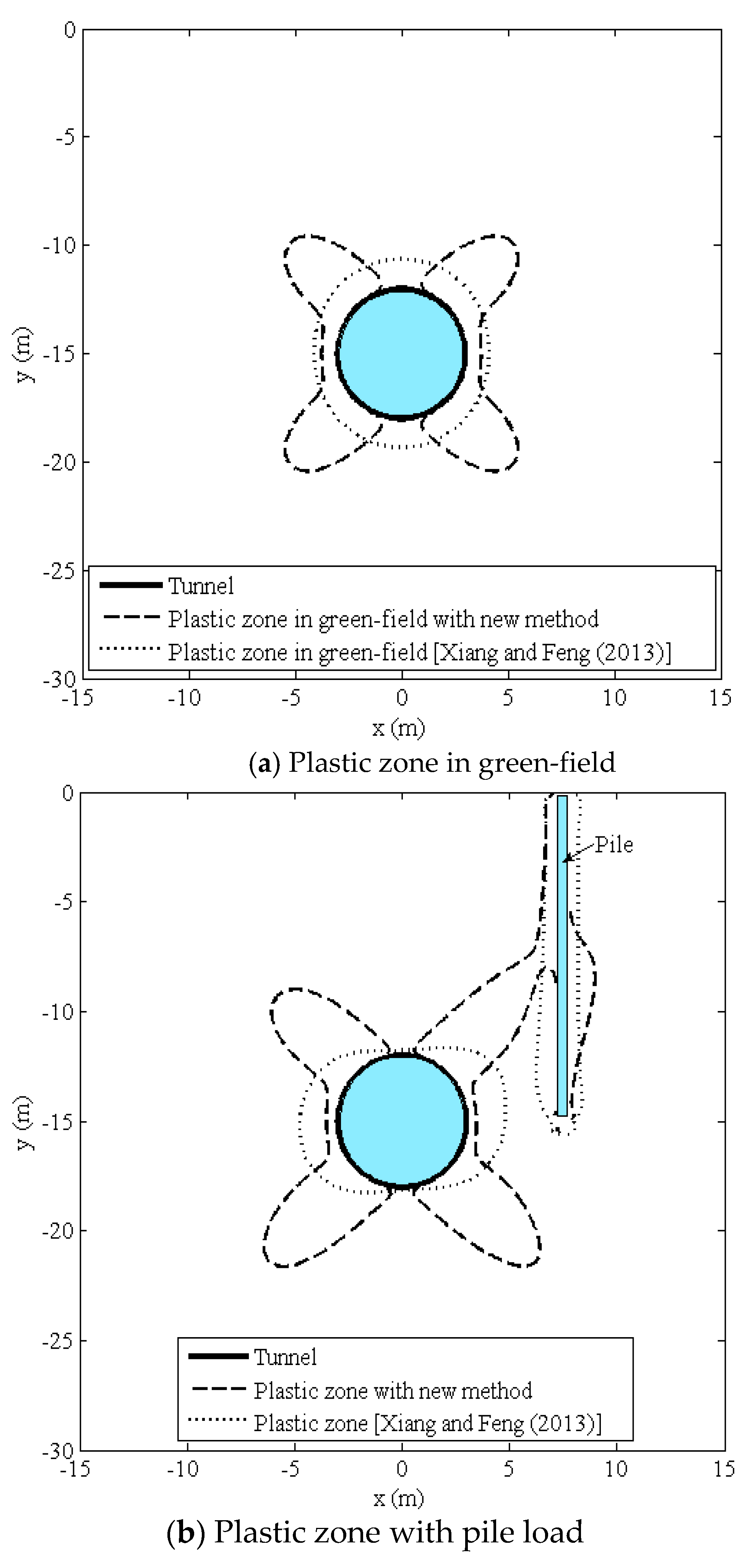
3.1. Comparisons with Xiang and Feng
To investigate the difference of the plastic zones in green-fields without pile loads and plastic zones with pile loads, the comparisons between the results obtained from this paper and those in [
11] were conducted as shown in
Figure 5. It can be seen that the potential plastic zone induced by nearby tunneling presents a butterfly shape when the gravity field is considered, whereas the shape of the potential plastic zone is circular when the gravity field is not considered.
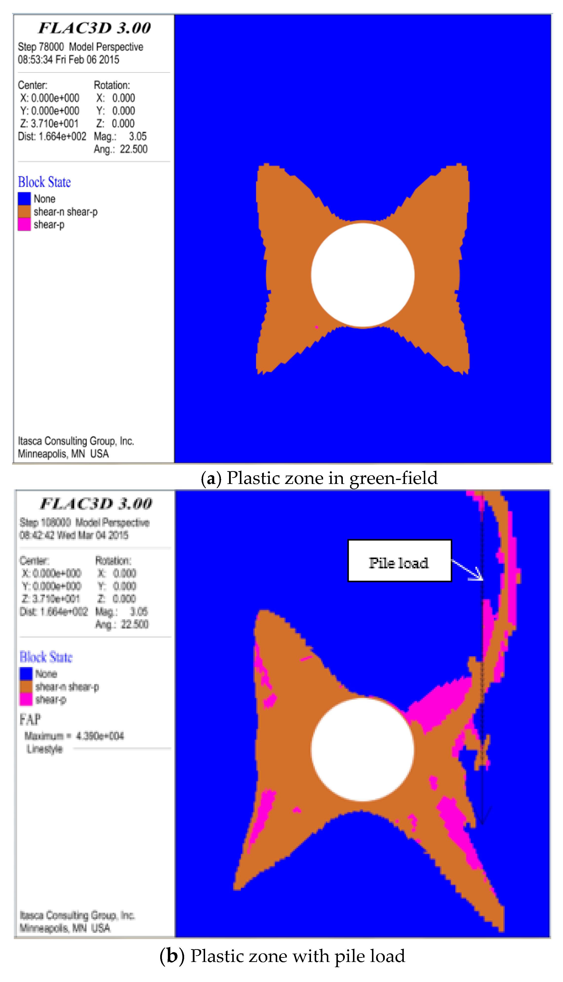
3.2. Comparisons with Numerical Simulations
Numerical simulations were performed by using the professional software FLAC3D (Itasca International Inc., Minneapolis, Minnesota, MN, USA) based on the identical parameters in
Table 1.
The results for the green-field and for the condition with pile load are shown in
Figure 6a,b, which are consistent with the corresponding theoretical results shown in
Figure 5a,b.
4. Parametric Analysis
A series of parametric studies were performed to systematically investigate the influence rules of different parameters of the prediction model, including the soil parameters, boundary conditions, and pile parameters, on the boundaries of the potential plastic zone in a gravity field. The parameter values of the control group are assumed to be: R = 3 m, h = 15 m, γ = 20 kN/m3, c = 30 kPa, φ = 25°, u0 = 9 cm, ud = 1.5 cm, Δuy = 0 cm, dp = 7 m, h0 = 15 m, s = 150 kN/m, P = 235 kN. When one studied parameter changes, the values of the other parameters remain the same.
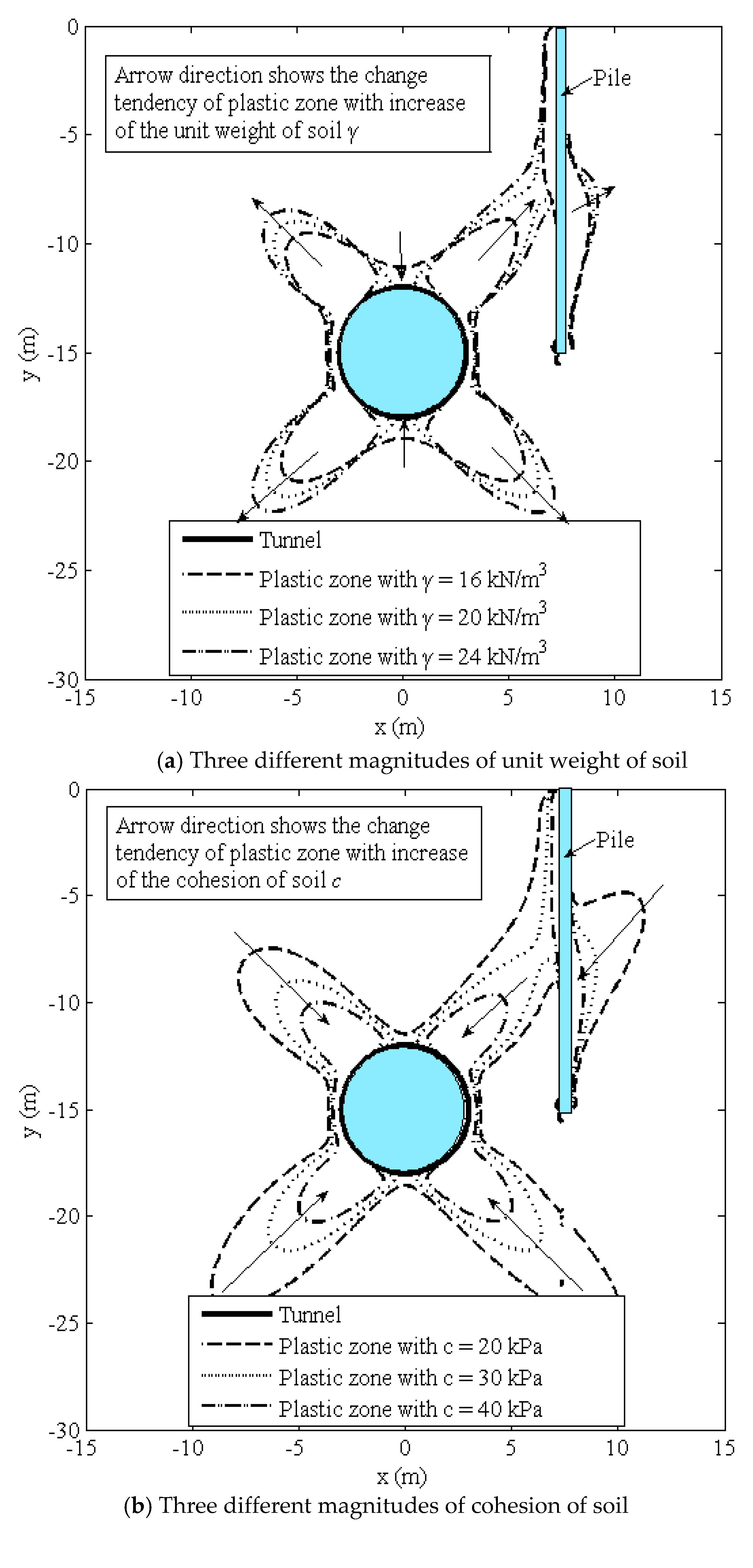
4.1. Influences of Soil Parameters
Figure 7 shows the influence rules of different soil parameters (unit weight, cohesion, and angle of internal friction) on the boundaries of the potential plastic zones.
In
Figure 7a, the influence of three different magnitudes of unit weight of soil (
γ =16 kN/m
3, 20 kN/m
3 and 24 kN/m
3) on the boundaries of the potential plastic zones is plotted. The arrow direction shows the change tendency of the plastic zone with the increase of the unit weight of soil. The results indicate that the boundaries of the potential plastic zone changed slightly with increased unit weight of soil. Four corners of the potential plastic zone extend outward and the midpoints of each side of the potential plastic zone contract inward, which shows that the shape of the potential plastic zone develops towards a butterfly shape with the increase of the unit weight of soil. Moreover, the two tunneling-induced potential plastic zones around the tunnel and the pile coalesce with the expansion of the tunneling-induced potential plastic zone.
The influence of three different magnitudes of cohesion of soil (
c = 20 kPa, 30 kPa, and 40 kPa) on the boundaries of the potential plastic zone is shown in
Figure 7b.
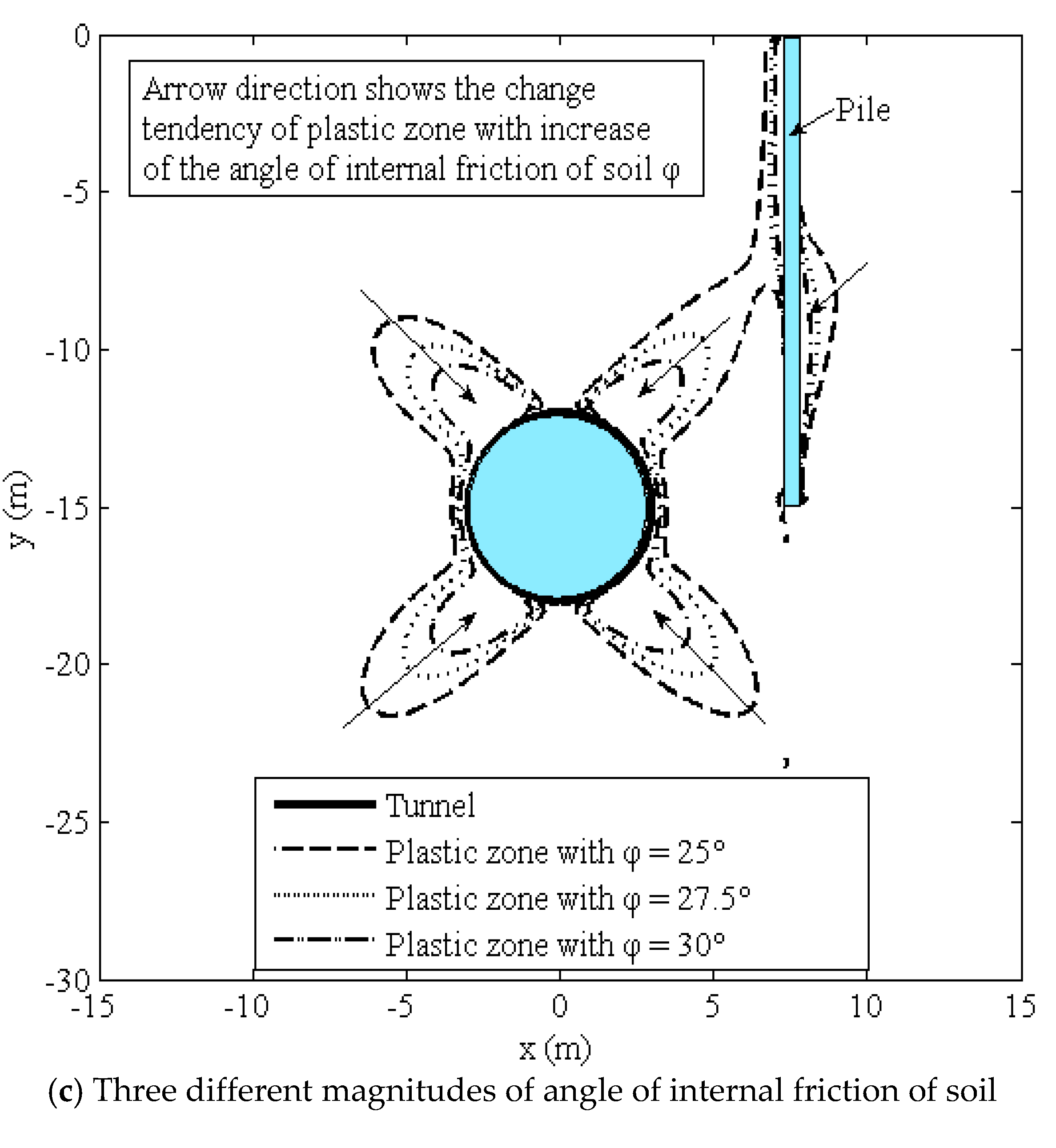
Figure 7c presents the influence of three different magnitudes of the angle of internal friction of the soil (
φ = 25°, 27.5°, and 30°) on the boundaries of the potential plastic zone. The results show that the influence rules are similar to each other. Moreover, it can be observed that when the cohesion or the angle of internal friction of the soil increases, the four corners of the potential plastic zone contract inward and the ranges of the potential plastic zone decrease significantly. In other words, the phenomenon of a butterfly-shaped potential plastic zone is apparent at a relatively low value of cohesion or angle of internal friction of the soil. It is worth noting that if the soil parameters (cohesion or angle of internal friction) are sufficiently large, the two tunneling-induced potential plastic zones around the tunnel and the pile would coalesce, whereas the two tunneling-induced potential plastic zones would separate from each other.
4.2. Influences of Different Tunnel Boundary Conditions
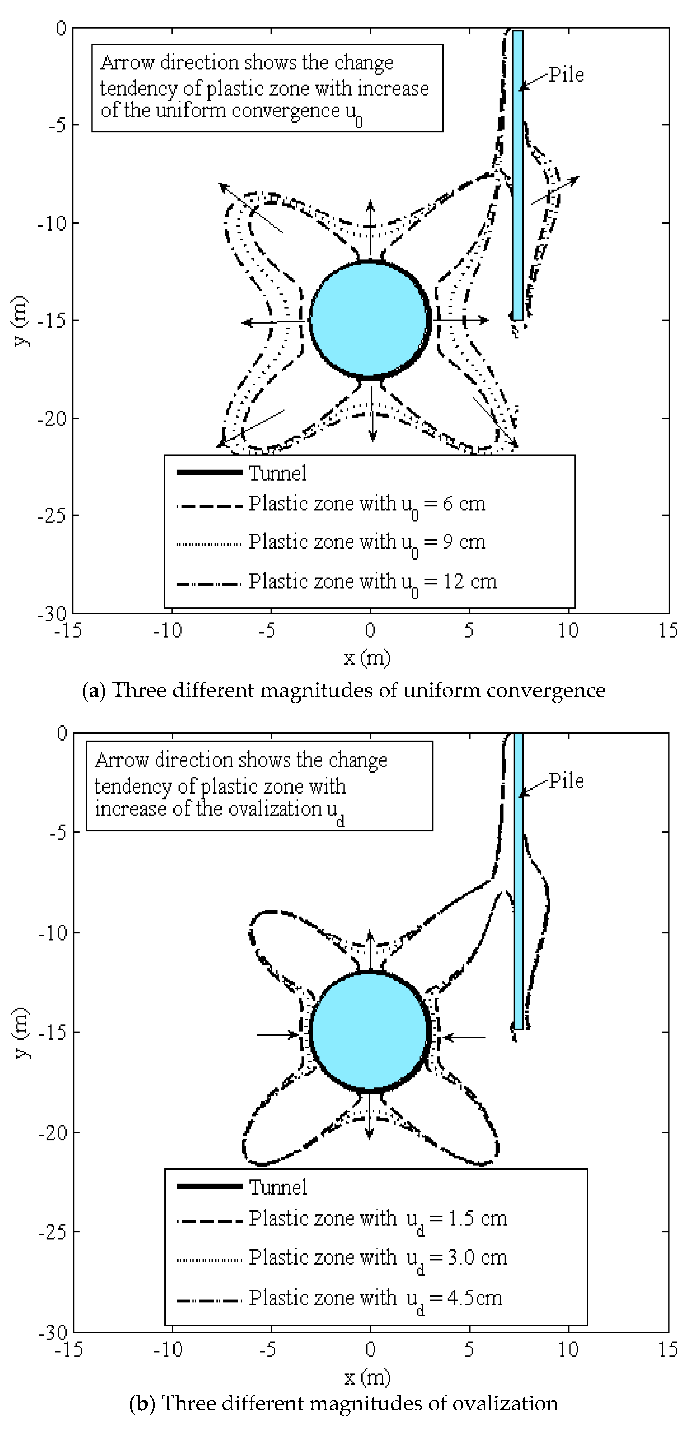
The influences of different tunnel boundary conditions (uniform convergence, ovalization, and vertical translation) on the boundaries of the potential plastic zones are shown in
Figure 8.
Figure 8a shows the influence of three different magnitudes of uniform convergence (
u0 = 6 cm, 9 cm and 12 cm) on the boundaries of the potential plastic zones. The results indicate that with the increase of uniform convergence, the shapes of the potential plastic zone change slightly and show the butterfly shape. However, the ranges of the potential plastic zone significantly increase with the increase of uniform convergence.
Figure 8b shows the influence of three different magnitudes of ovalization (
ud = 1.5 cm, 3 cm and 4.5 cm) on the boundaries of the potential plastic zones. It can be observed that when ovalization increases, both sides of the up and down of the potential plastic zone extend outward when ovalization increases and both sides of the left and right of the potential plastic zone contract inward, thus showing the development of a vertical bone-shaped potential plastic zone.
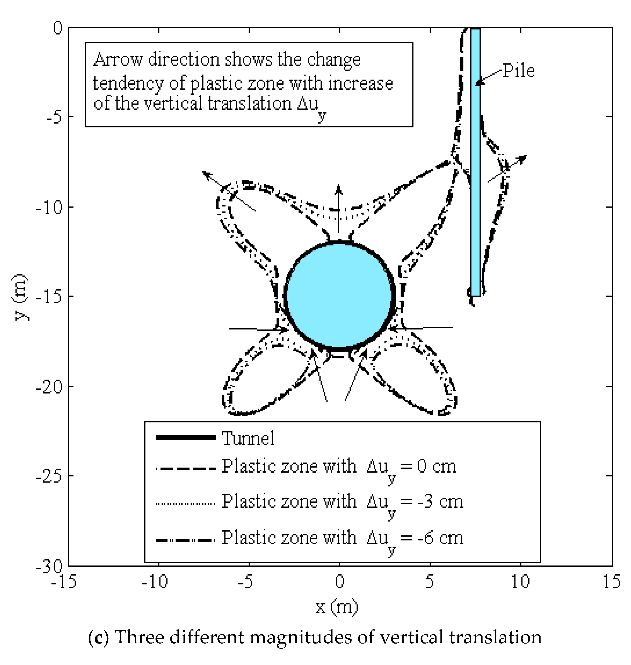
The influence of three different magnitudes of vertical translation (Δ
uy = 0 cm, −3 cm and −6 cm) on the boundaries of the potential plastic zone induced by tunneling is shown in
Figure 8c. It can be observed that when the vertical translation increases, the up side of the potential plastic zone extends outward and the down side of the potential plastic zone contracts inward, which shows that the shape of the potential plastic zone develops towards a fan shape.
It should be noted that the uniform convergence of a tunnel primarily affects the range of the potential plastic zone, whereas the ovalization of a tunnel primarily affects the shape of the potential plastic zone. The vertical translation affects both the range and the shape of the potential plastic zone.
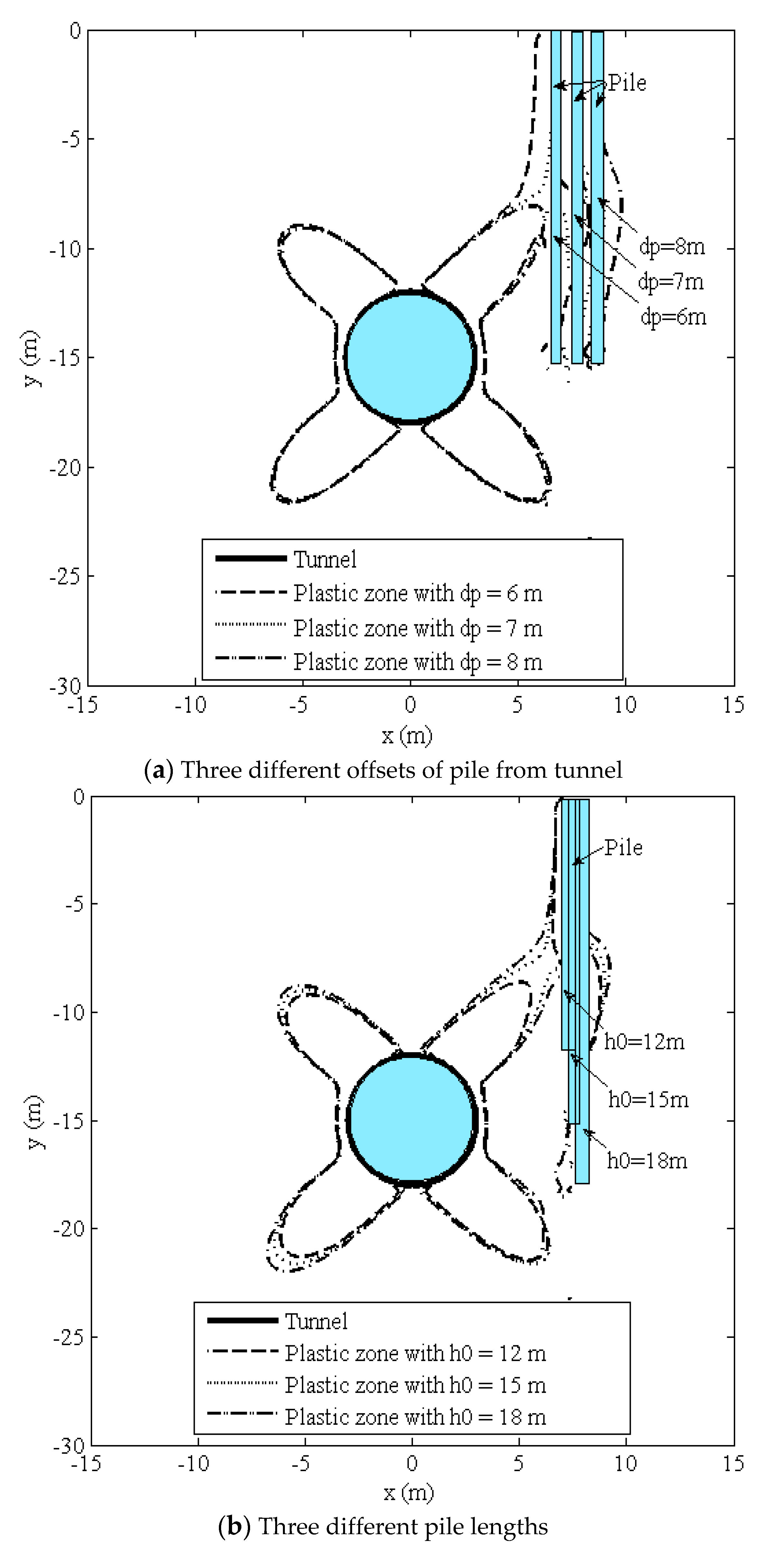
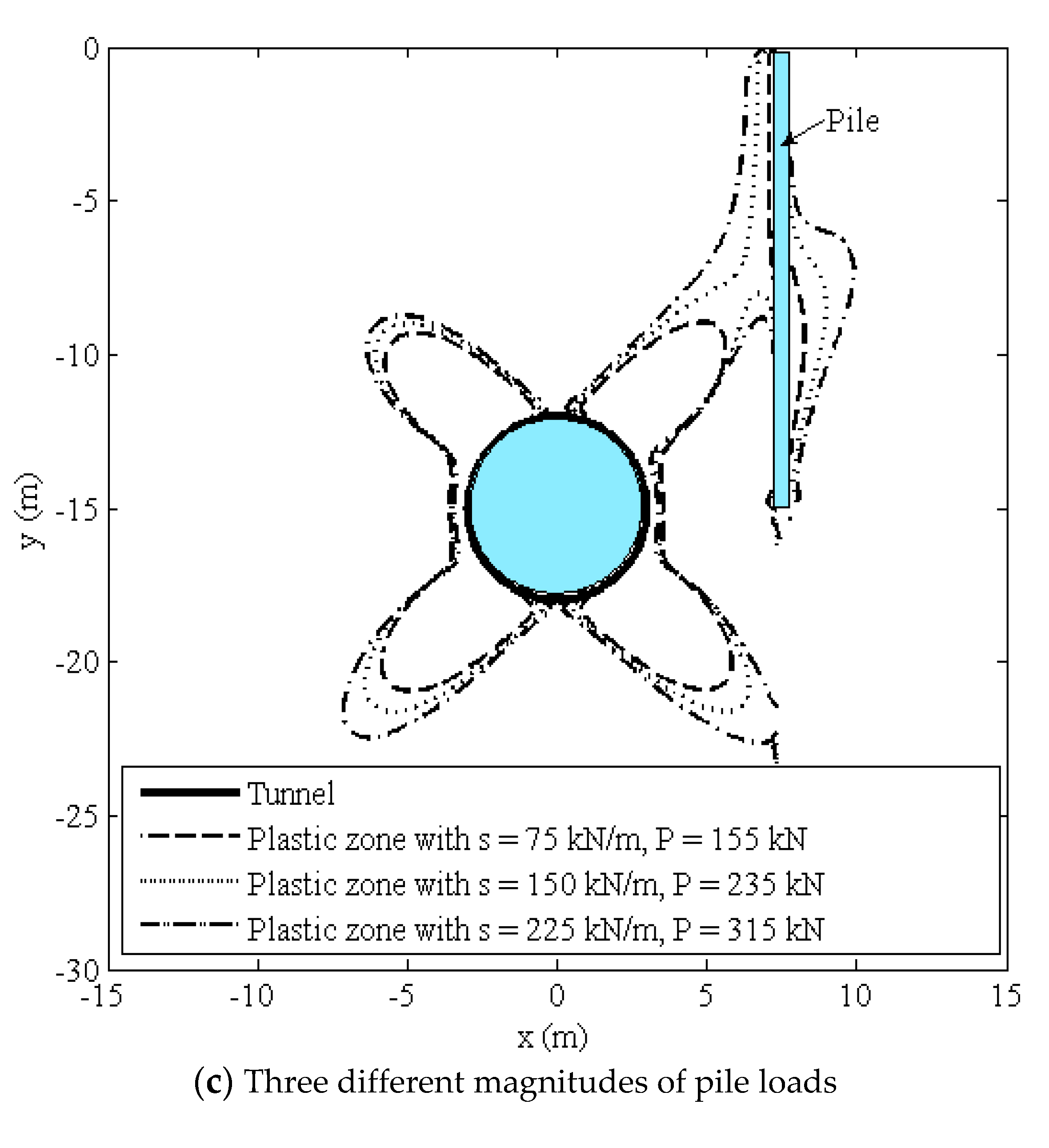
4.3. Influences of Pile Parameters
The influences of different pile parameters (pile offsets, pile length and load magnitude) on the boundaries of the potential plastic zones are analyzed in
Figure 9. The results indicate that the potential plastic zones near the tunnel and near the pile are connected when the pile is located close enough to the tunnel, the depth of the pile tip is near the level of the tunnel spring line and the pile loads are large enough.
5. Conclusions
This paper proposed an analytical approach to predict the potential plastic zone induced by tunnel excavation adjacent to a pile foundation in a gravity field. The major conclusions are presented as follows:
- (1)
Comparisons with existing approaches and numerical simulations were conducted to verify the proposed superposition method in this paper. The results from the theoretical methods were similar to those from the numerical simulations, indicating that the potential plastic zone develops towards a butterfly shape in a gravity field.
- (2)
With increases of the cohesion or the angle of internal friction of the soil, the ranges of the potential plastic zone decrease significantly, and the potential plastic zone develops towards a butterfly shape. However, with increasing unit weight of the soil, the boundaries of the potential plastic zone change slightly.
- (3)
The uniform convergence of a tunnel primarily affects the range of a potential plastic zone, whereas the ovalization of a tunnel primarily affects the shape of a potential plastic zone. The vertical translation affects both the range and the shape of the potential plastic zone. Moreover, the increase of uniform convergence, ovalization, and vertical translation develops different potential plastic zone shapes; butterfly-shaped, vertical bone-shaped, and fan-shaped, respectively.
- (4)
The two potential plastic zones around the tunnel and around the pile are connected when the pile is sufficiently close to the tunnel (or the pile length is near the level of the tunnel spring line, or the magnitude of the pile loads is large enough), whereas the two plastic zones are separated from each other. It is worth noting that this conclusion is valid only for the specific terrain parameters used in our paper. More studies of different strata conditions will be conducted in the future.
Author Contributions
Y.F., K.H. and D.S. conceived of the idea of using a prediction model to analyze the potential plastic zone induced by tunneling adjacent to a pile foundation in a gravity field. X.P., X.B. B.H., H.W. and J.W. completed most of the details of the calculations.
Funding
The National Natural Science Foundation of China (Grant no. 51938008, 51908371, 51678363) provided financial support for the authors.
Conflicts of Interest
The authors declare no conflict of interest.
References
- Lee, C.J.; Bolton, M.D.; Tabbaa, A.A. Numerical modeling of group effects on the distribution of dragloads in pile foundations. Géotechnique 2002, 52, 325–335. [Google Scholar] [CrossRef]
- Lee, C.J.; Ng, C.W.W. Development of downdrag on piles and pile groups in consolidating soil. J. Geotech. Geoenviron. 2004, 132, 905–914. [Google Scholar] [CrossRef]
- Liu, C.; Zhang, Z.; Regueiro, R.A. Pile and pile group response to tunnelling using a large diameter slurry shield-Case study in Shanghai. Comput. Geotech. 2014, 59, 21–43. [Google Scholar] [CrossRef]
- Soomro, M.A.; Hong, Y.; Ng, C.W.W.; Lu, H.; Peng, S. Load transfer mechanism in pile group due to single tunnel advancement in stiff clay. Tunn. Undergr. Space Technol. 2015, 45, 63–72. [Google Scholar] [CrossRef]
- Loganathan, N.; Poulos, H.G.; Xu, K.J. Ground and pile-group response due to tunneling. Soils Found. 2001, 41, 57–67. [Google Scholar] [CrossRef]
- Marshall, A.M. Tunnel-pile interaction analysis using cavity expansion methods. J. Geotech. Geoenviron. 2012, 138, 1237–1246. [Google Scholar] [CrossRef]
- Marshall, A.M.; Haji, T. An analytical study of tunnel-pile interaction. Tunn. Undergr. Space Technol. 2015, 45, 43–51. [Google Scholar] [CrossRef]
- Lee, Y.J.; Banssett, R.H. Influence zones for 2D pile-soil-tunneling interaction based on model test and numerical analysis. Tunn. Undergr. Space Technol. 2007, 22, 325–342. [Google Scholar] [CrossRef]
- Chang, K.H.; Lee, C.J. Responses of single piles to tunneling-induced soil movements in sandy ground. Can. Geotech. J. 2007, 44, 1224–1241. [Google Scholar] [CrossRef]
- Ng, C.W.W.; Lu, H.; Peng, S.Y. Three-dimensional centrifuge modelling of the effects of twin tunnelling on an existing pile. Tunn. Undergr. Space Technol. 2013, 35, 189–199. [Google Scholar] [CrossRef]
- Xiang, Y.; Feng, S. Theoretical prediction of the potential plastic zone of shallow tunneling adjacent to pile foundation in soils. Tunn. Undergr. Space Technol. 2013, 38, 115–121. [Google Scholar] [CrossRef]
- Guo, C.X.; Han, K.H.; Kong, H.; Shi, L.L. Explicit form of exact analytical solution for calculating ground displacement and stress induced by shallow tunneling and its application. Adv. Civ. Eng. 2019, 2019, 5739123. [Google Scholar] [CrossRef]
- Li, Z.; Wang, J.; Han, K. Analytical Solution of Ground Stress Induced by Shallow Tunneling with Arbitrary Distributed Loads on Ground Surface. Symmetry 2019, 11, 823. [Google Scholar] [CrossRef]
- Mindlin, R.D. Force at a point in the interior of a semi-infinite solid. Physics 1936, 7, 195–202. [Google Scholar] [CrossRef]
- Park, K.H. Elastic solution for tunneling-induced ground movements in clays. Int. J. Geomech. 2004, 4, 310–318. [Google Scholar] [CrossRef]
- Pinto, F.; Whittle, A.J. Ground movements due to shallow tunnels in soft ground. I: Analytical solutions. J. Geotech. Geoenviron. 2013, 140, 04013040. [Google Scholar] [CrossRef]
- Tong, L.; Xie, K.H.; Cheng, Y.F.; Lu, M.M.; Wang, K. Elastic solution of sallow tunnels in clays considering oval deformation of ground. Rock Soil Mech. 2009, 30, 393–398. (In Chinese) [Google Scholar]
© 2019 by the authors. Licensee MDPI, Basel, Switzerland. This article is an open access article distributed under the terms and conditions of the Creative Commons Attribution (CC BY) license (http://creativecommons.org/licenses/by/4.0/).

 ,
, 


