A Computational Design Method for Tucking Axisymmetric Origami Consisting of Triangular Facets

Abstract
:1. Introduction
2. Related Work
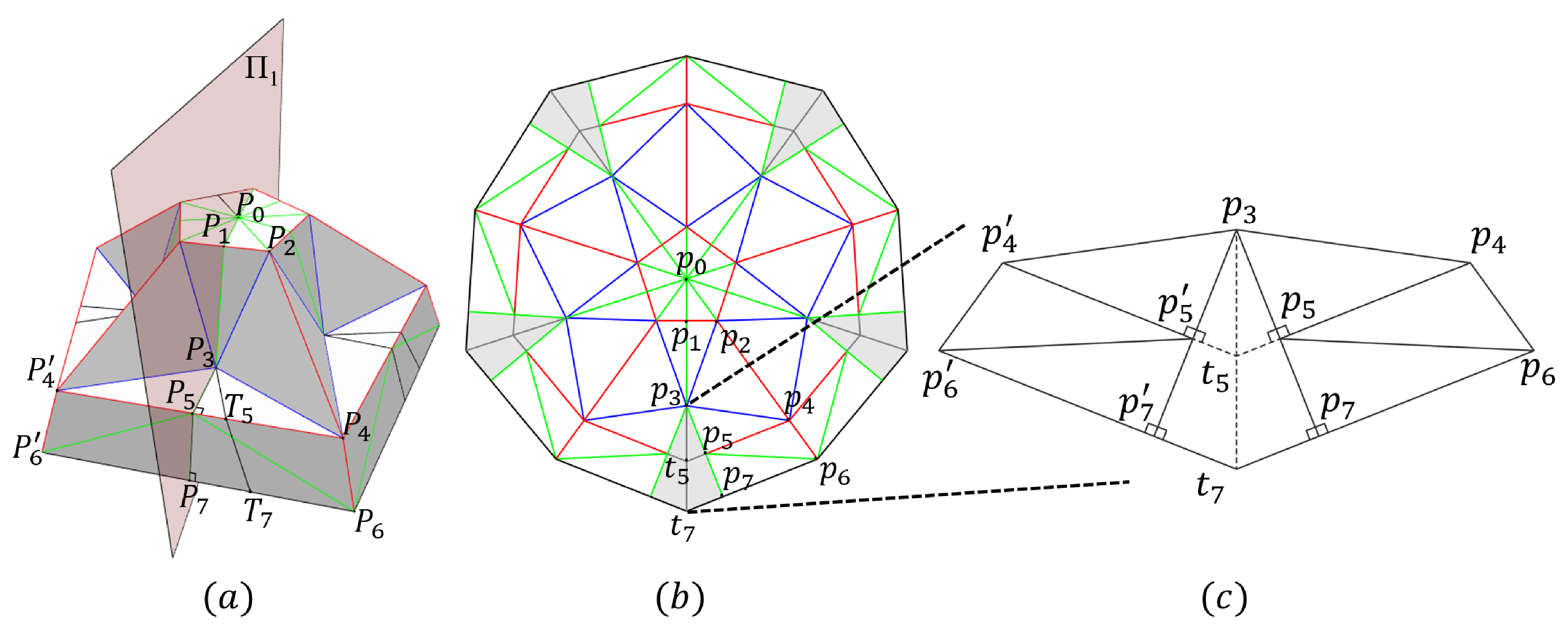
3. Methodology
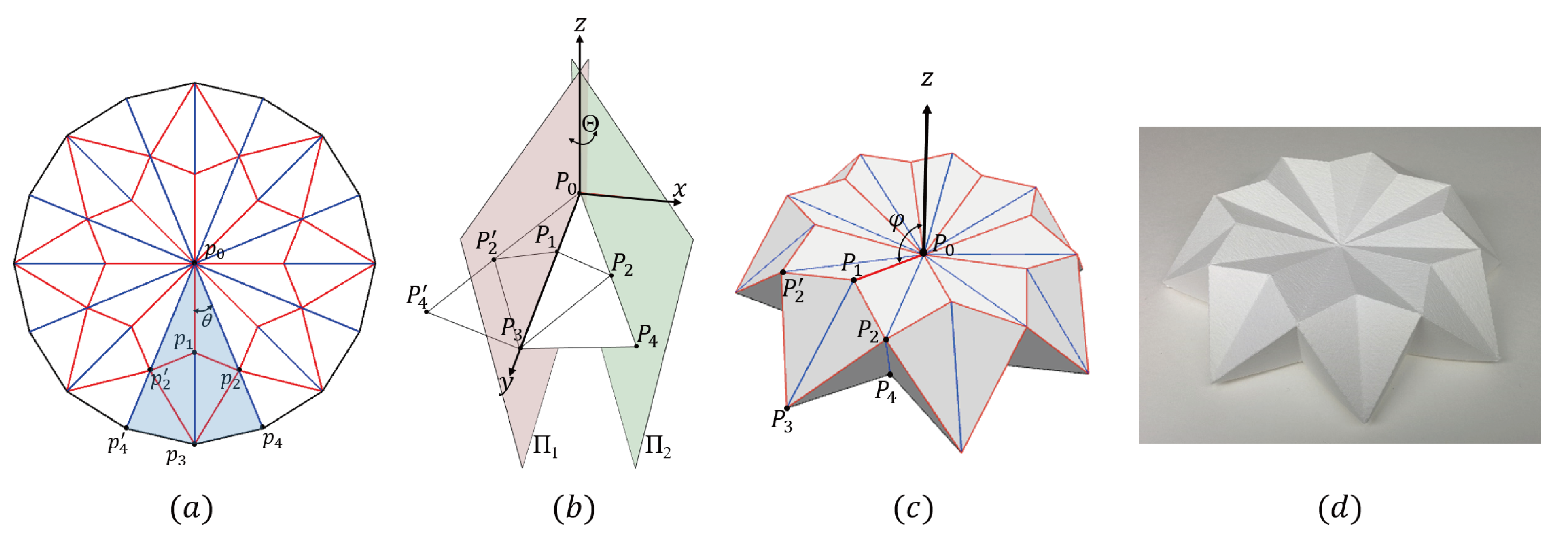
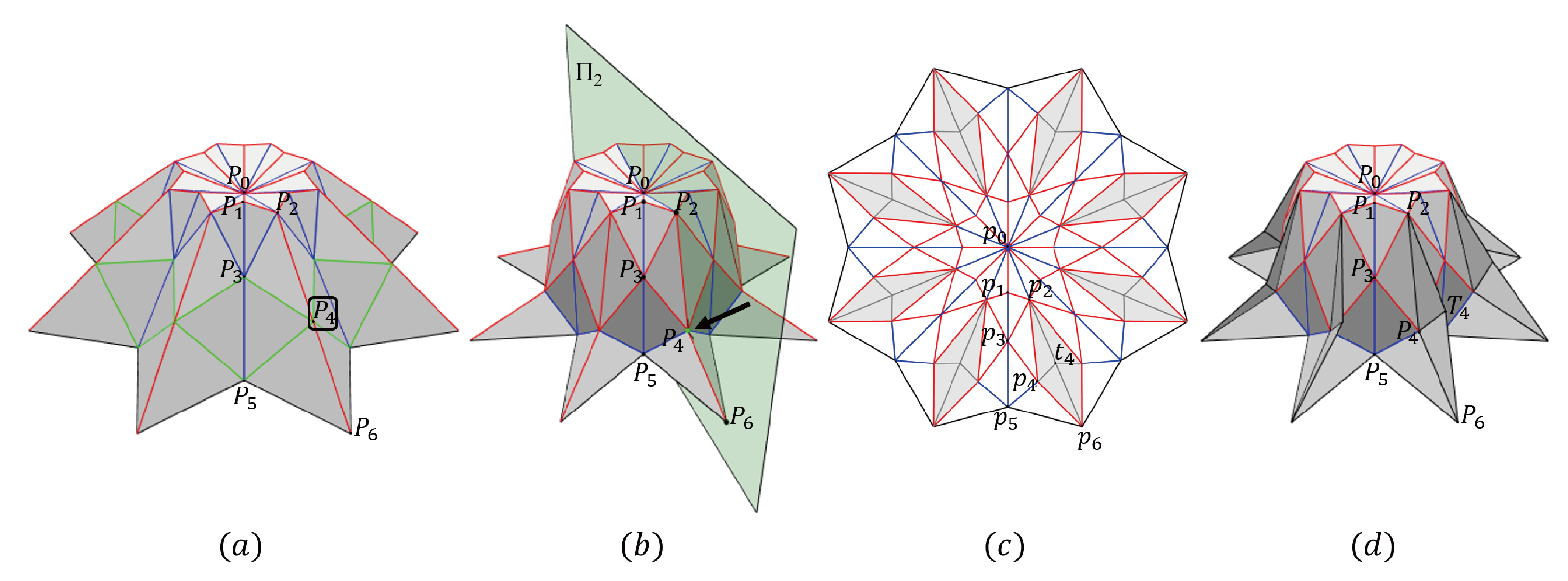
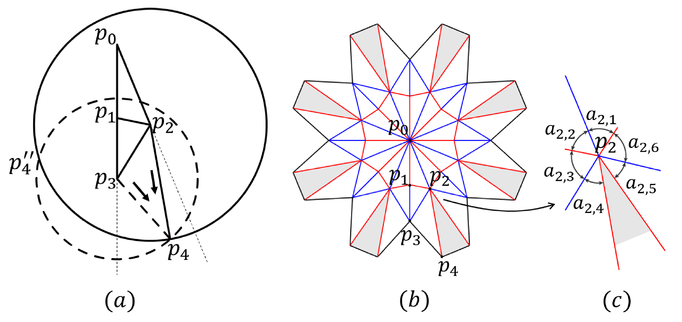
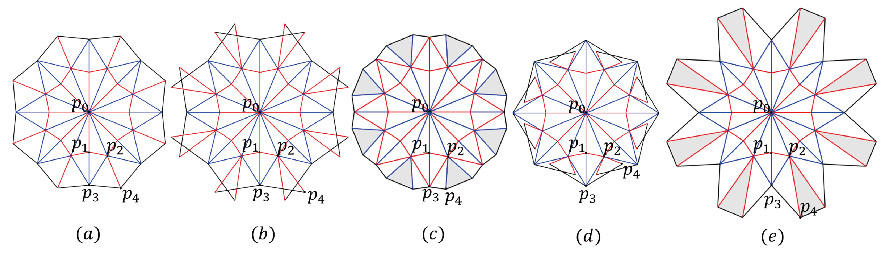
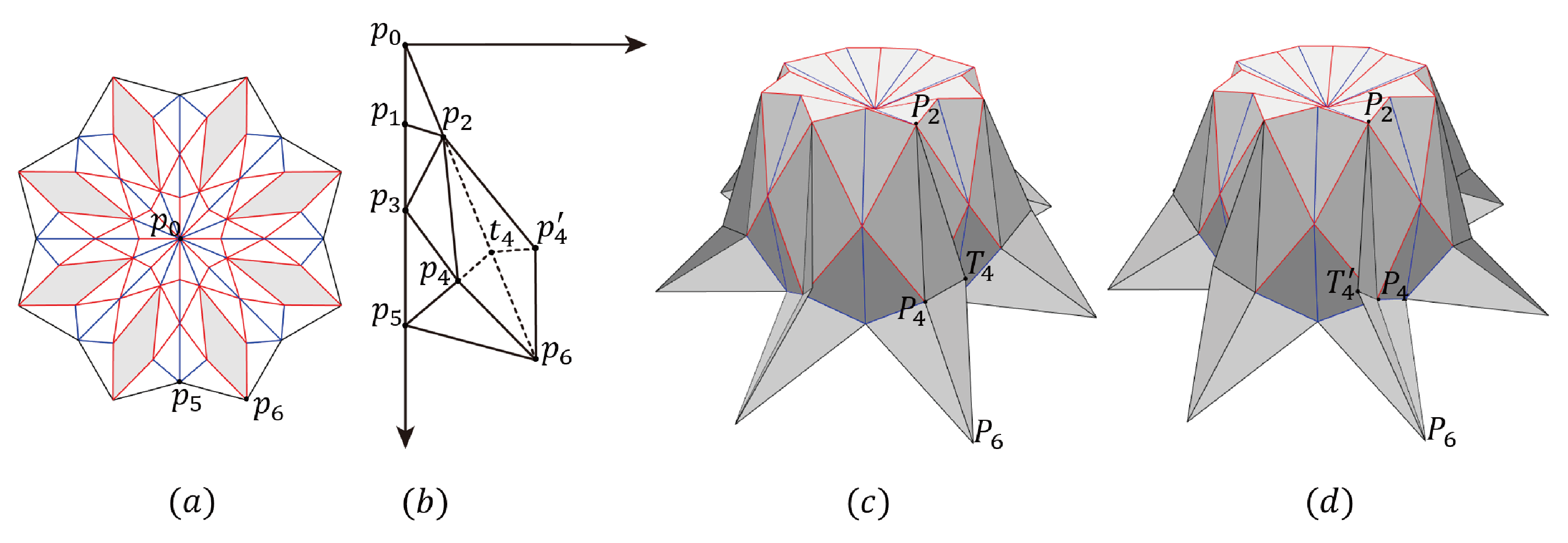
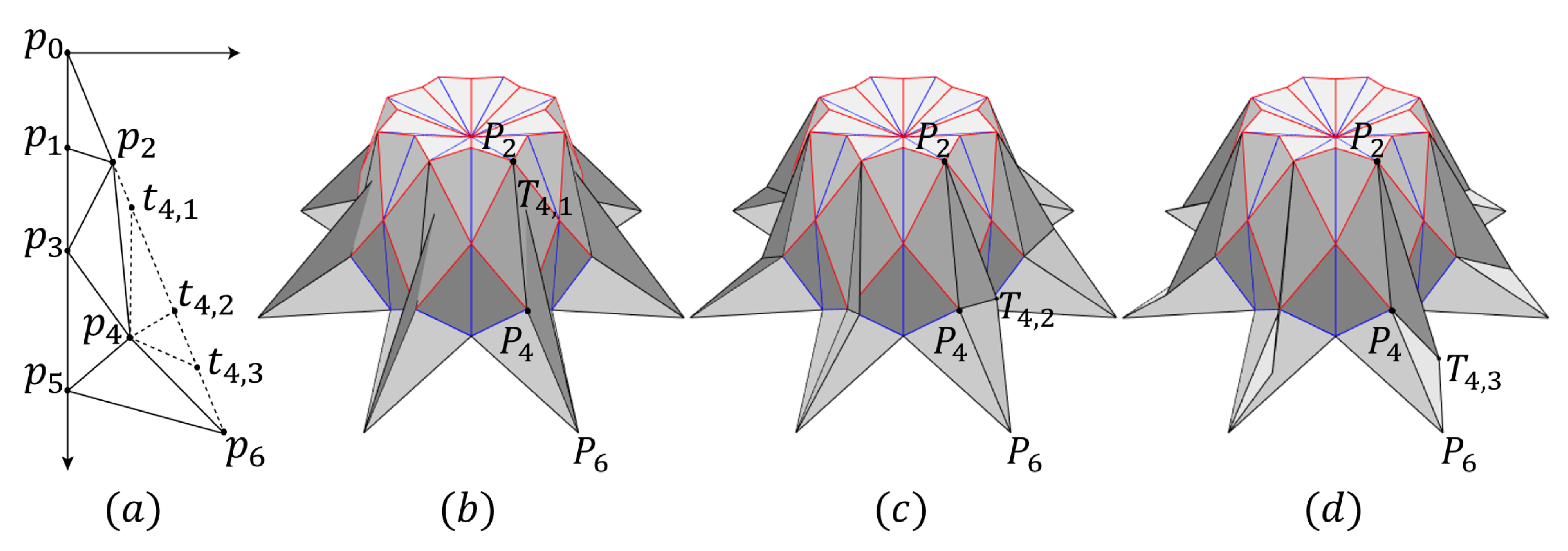
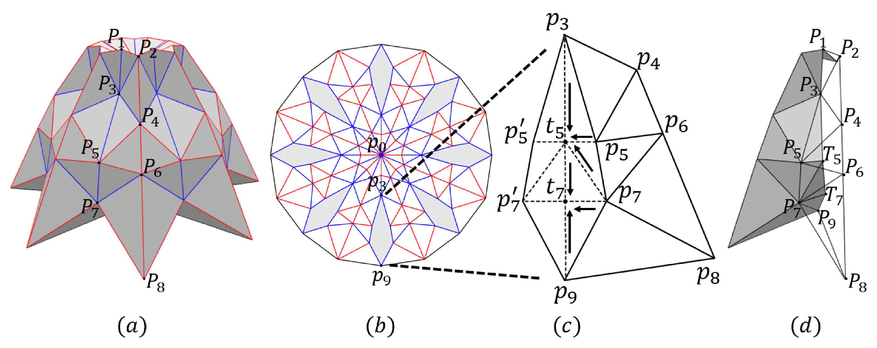
3.1. Designing 3D Origami
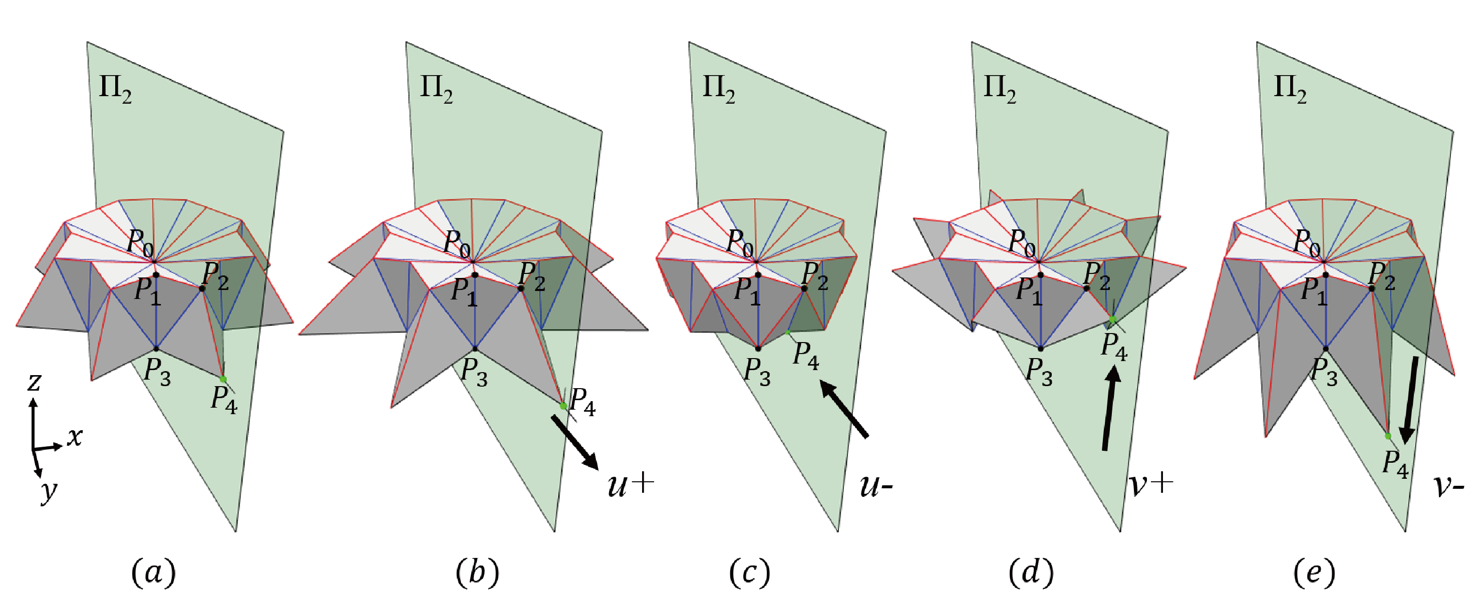
3.2. Special Case of 3D Flaps
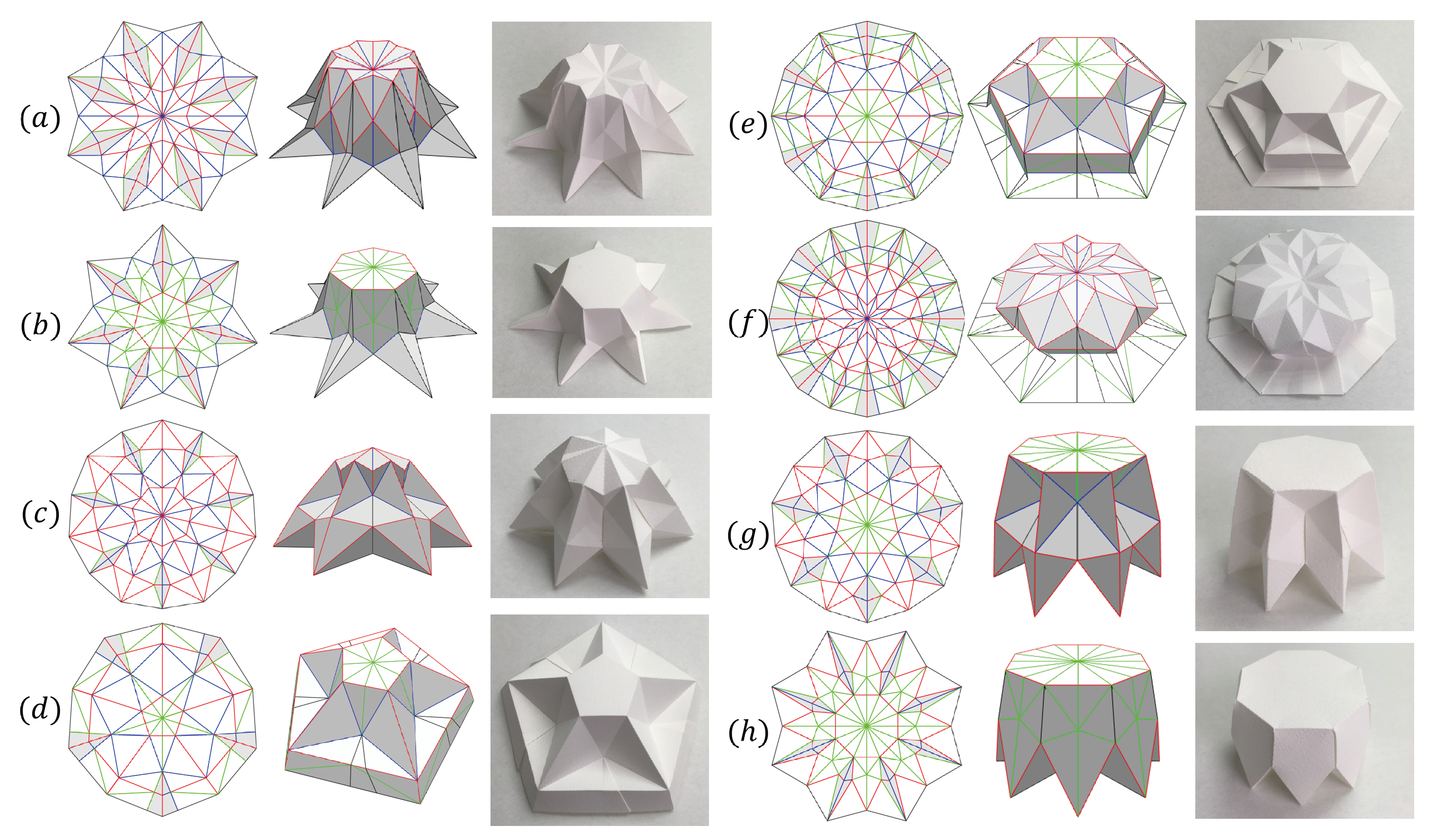
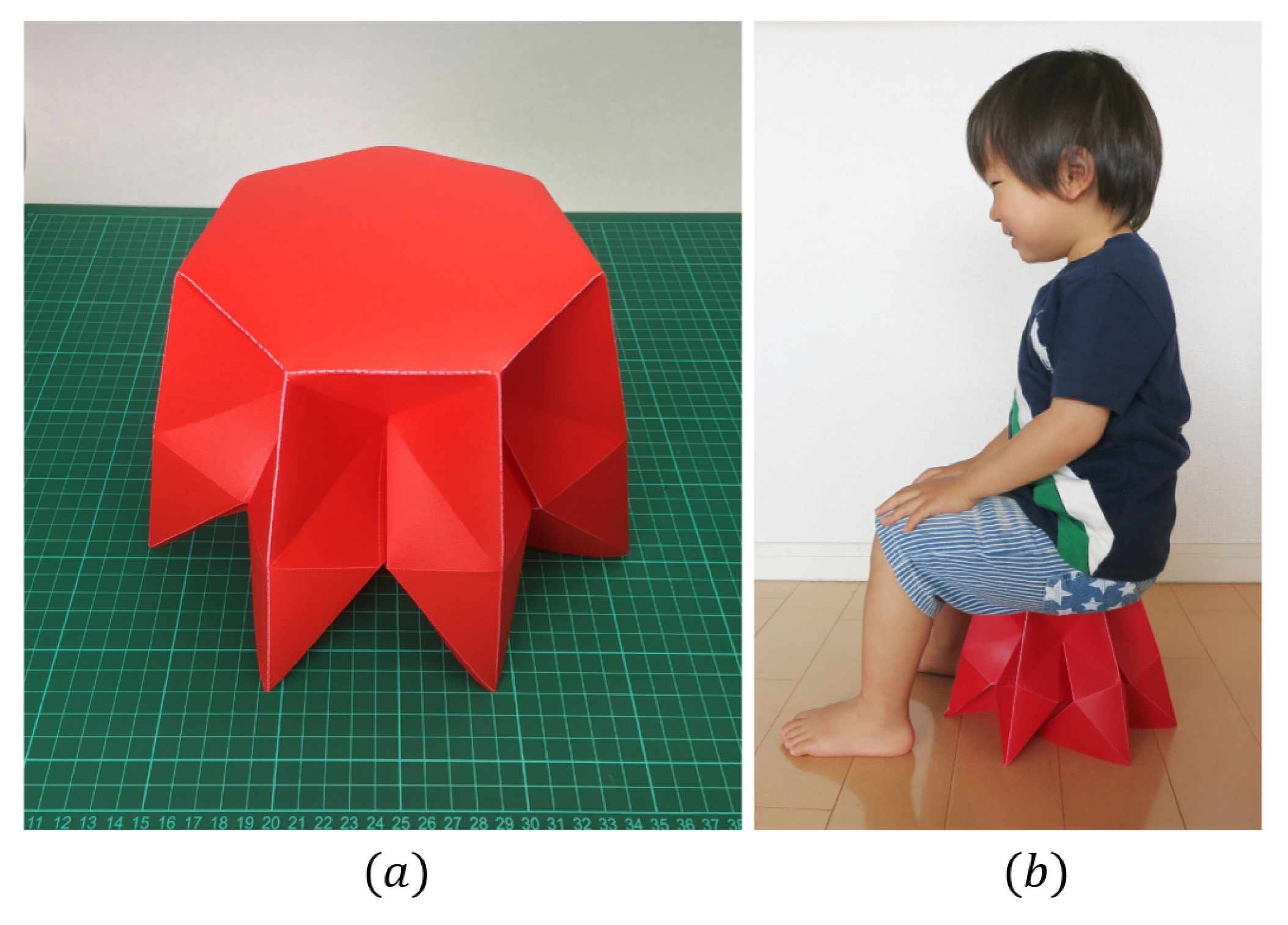
4. Results and Discussion
5. Conclusions
Author Contributions
Funding
Conflicts of Interest
References
- Mitani, J. A method for designing crease patterns for flat-foldable origami with numerical optimization. J. Geom. Graph. 2011, 15, 195–201. [Google Scholar]
- Demaine, E.D.; Demaine, M.L. Recent results in computational origami. In Origami 3: Third International Meeting of Origami Science, Mathematics and Education; A K Peters/CRC Press: Boca Raton, FL, USA, 2002; pp. 3–16. [Google Scholar]
- Tang, C.; Bo, P.; Wallner, J.; Pottmann, H. Interactive design of developable surfaces. ACM Trans. Graph. 2016, 35, 12. [Google Scholar] [CrossRef]
- Callens, S.J.; Zadpoor, A.A. From flat sheets to curved geometries: Origami and kirigami approaches. Mater. Today 2018, 21, 241–264. [Google Scholar] [CrossRef]
- Solomon, J.; Vouga, E.; Wardetzky, M.; Grinspun, E. Flexible developable surfaces. Comput. Graph. Forum 2012, 31, 1567–1576. [Google Scholar] [CrossRef]
- Tachi, T. Origamizing polyhedral surfaces. IEEE Trans. Vis. Comput. Graph. 2010, 16, 298–311. [Google Scholar] [CrossRef] [PubMed]
- Mitani, J. A design method for 3D origami based on rotational sweep. Comput.-Aided Des. Appl. 2009, 6, 69–79. [Google Scholar] [CrossRef]
- Mitani, J. A Design Method for Axisymmetric Curved Origami with Triangular Prism Protrusions. In Origami 5: Fifth International Meeting of Origami Science, Mathematics, and Education; CRC Press: Boca Raton, FL, USA, 2011; pp. 437–447. [Google Scholar]
- Mitani, J. Column-shaped Origami Design Based on Mirror Reflections. J. Geom. Graph. 2012, 16, 185–194. [Google Scholar]
- Tachi, T. Freeform variations of origami. J. Geom. Graph. 2010, 14, 203–215. [Google Scholar]
- Tachi, T. Freeform rigid-foldable structure using bidirectionally flat-foldable planar quadrilateral mesh. Adv. Archit. Geom. 2010, 2010, 87–102. [Google Scholar]
- Mitani, J.; Igarashi, T. Interactive design of planar curved folding by reflection. In Proceedings of the Pacific Conference on Computer Graphics and Applications, Kaohsiung, Taiwan, 21–23 September 2011; pp. 77–81. [Google Scholar]
- Nangreave, J.; Han, D.; Liu, Y.; Yan, H. DNA origami: A history and current perspective. Curr. Opin. Chem. Biol. 2010, 14, 608–615. [Google Scholar] [CrossRef] [PubMed]
- Zhang, Q.; Jiang, Q.; Li, N.; Dai, L.; Liu, Q.; Song, L.; Wang, J.; Li, Y.; Tian, J.; Ding, B.; et al. DNA origami as an in vivo drug delivery vehicle for cancer therapy. ACS Nano 2014, 8, 6633–6643. [Google Scholar] [CrossRef] [PubMed]
- Felton, S.; Tolley, M.; Demaine, E.; Rus, D.; Wood, R. A method for building self-folding machines. Science 2014, 345, 644–646. [Google Scholar] [CrossRef] [PubMed]
- Miura, K. Map fold a la Miura style, its physical characteristics and application to the space science. Res. Pattern Form. 1994, 77–90. [Google Scholar]
- Zirbel, S.A.; Lang, R.J.; Thomson, M.W.; Sigel, D.A.; Walkemeyer, P.E.; Trease, B.P.; Magleby, S.P.; Howell, L.L. Accommodating thickness in origami-based deployable arrays. J. Mech. Des. 2013, 135, 111005. [Google Scholar] [CrossRef]
- Zirbel, S.A.; Trease, B.P.; Thomson, M.W.; Lang, R.J.; Magleby, S.P.; Howell, L.H. HanaFlex: A large solar array for space applications. In Micro- and Nanotechnology Sensors, Systems, and Applications VII; International Society for Optics and Photonics: Washington, DC, USA, 2015; Volume 9467, p. 94671C. [Google Scholar]
- Zhao, Y.; Kanamori, Y.; Mitani, J. Geometry of Axisymmetric 3D Origami Consisting of Triangular Facets. J. Geom. Graph. 2017, 1, 107–118. [Google Scholar]
- Ohtake, Y.; Belyaev, A.; Seidel, H.P. Ridge-valley lines on meshes via implicit surface fitting. ACM Trans. Graph. 2004, 23, 609–612. [Google Scholar] [CrossRef]
- Lang, R.J. TreeMaker. Available online: http://www.langorigami.com/article/treemaker/ (accessed on 10 September 2018).
- Meguro, T. The method to design origami. Origami Tanteidan Newspaper, 10 September 1991. [Google Scholar]
- Lang, R.J. A computational algorithm for origami design. In Proceedings of the Twelfth Annual Symposium on Computational Geometry, Philadelphia, PA, USA, 24–26 May 1996; pp. 98–105. [Google Scholar]
- Bateman, A. Paper Mosaic Origami Tessellations. Available online: http://www.papermosaics.co.uk/software.html (accessed on 10 September 2018).
- Demaine, E.D.; Tachi, T. Origamizer: A Practical Algorithm for Folding Any Polyhedron. 2017, Volume 77. Available online: http://drops.dagstuhl.de/opus/volltexte/2017/7231/ (accessed on 10 September 2018).
- Bartoň, M.; Shi, L.; Kilian, M.; Wallner, J.; Pottmann, H. Circular arc snakes and kinematic surface generation. Comput. Graph. Forum 2013, 32, 1–10. [Google Scholar] [CrossRef]
- Bartoň, M.; Pottmann, H.; Wallner, J. Detection and reconstruction of freeform sweeps. Comput. Graph. Forum 2014, 33, 23–32. [Google Scholar] [CrossRef]
- Zhao, Y.; Kanamori, Y.; Mitani, J. Design and motion analysis of axisymmetric 3D origami with generic six-crease bases. Comput.-Aided Geom. Des. 2018, 59, 86–97. [Google Scholar] [CrossRef]
- Dudte, L.H.; Vouga, E.; Tachi, T.; Mahadevan, L. Programming curvature using origami tessellations. Nat. Mater. 2016, 15, 583–588. [Google Scholar] [CrossRef] [PubMed]
- Zhao, Y.; Endo, Y.; Kanamori, Y.; Mitani, J. Approximating 3D surfaces using generalized waterbomb tessellations. J. Comput. Des. Eng. 2018, 5, 442–448. [Google Scholar] [CrossRef]
- Kuribayashi, K.; Tsuchiya, K.; You, Z.; Tomus, D.; Umemoto, M.; Ito, T.; Sasaki, M. Self-deployable origami stent grafts as a biomedical application of Ni-rich TiNi shape memory alloy foil. Mater. Sci. Eng. A 2006, 419, 131–137. [Google Scholar] [CrossRef]


© 2018 by the authors. Licensee MDPI, Basel, Switzerland. This article is an open access article distributed under the terms and conditions of the Creative Commons Attribution (CC BY) license (http://creativecommons.org/licenses/by/4.0/).
Share and Cite
Zhao, Y.; Endo, Y.; Kanamori, Y.; Mitani, J. A Computational Design Method for Tucking Axisymmetric Origami Consisting of Triangular Facets. Symmetry 2018, 10, 469. https://doi.org/10.3390/sym10100469
Zhao Y, Endo Y, Kanamori Y, Mitani J. A Computational Design Method for Tucking Axisymmetric Origami Consisting of Triangular Facets. Symmetry. 2018; 10(10):469. https://doi.org/10.3390/sym10100469
Chicago/Turabian StyleZhao, Yan, Yuki Endo, Yoshihiro Kanamori, and Jun Mitani. 2018. "A Computational Design Method for Tucking Axisymmetric Origami Consisting of Triangular Facets" Symmetry 10, no. 10: 469. https://doi.org/10.3390/sym10100469