1. Introduction
With the implementation of China’s One Belt One Road (OBOR) initiative and Western Development strategy, deep tunneling has become a key control project among the major projects [
1,
2]. Weak rock strata under high ground stress are prone to fragmentation of surrounding rocks, strong rheological property, supporting body failure, and other nonlinear mechanical phenomena [
1,
3]. Moreover, in the construction of tunnels in water-rich strata, groundwater will flood into the tunnel due to the influence of groundwater seepage, which will deteriorate the stability of the surrounding rock and bury construction personnel and equipment in severe cases. In the tunnel operation phase, groundwater seepage will have many adverse effects and even threatens the tunnel’s structural stability, cave facilities, and traffic safety. The long-term drainage of tunnels will cause environmental disasters such as falling groundwater levels, ground subsidence, and disconnection of important water sources [
4]. Grouting to block off the seepage channels and strengthen the mechanical properties of broken surrounding rock has been widely used in geotechnical engineering [
5,
6]. It is noteworthy that the grouting migration law of broken surrounding rocks in deep tunnels has an important impact on grouting process parameters (such as grouting row spacing, grouting pressure, etc.).
Predecessors have achieved plentiful and substantial outcomes of the research on grouting. To name a few, in terms of grouting theory, the classical permeation grouting theory, compaction grouting theory, fracture grouting theory, and their optimization are proposed [
7,
8,
9,
10,
11,
12,
13,
14]; in terms of grouting material, such as cement-based slurry, sodium silicate, silica sol, and other optimized slurry materials were studied [
15,
16,
17,
18,
19,
20]; in terms of diffusion mechanism of grouting slurry, the slurry diffusion mechanism has been studied considering the time-varying characteristics of viscosity [
21,
22,
23], temperature-varying characteristics [
24,
25], and multi-field coupling [
26,
27]. In the research on permeation grouting with broken surrounding rock, Pan D.J. et al. applied nanosilica to grout in broken coal mass and studied the diffusion mechanism of the grouting material [
17,
27,
28]; Zheng, W.H. et al., Liu, and J.Q. et al. designed the grouting parameters by means of experiments and field investigations using weathered granite tunnels as example [
29,
30]; Liu X.L. et al. analyzed the tunnel grouting process of silty fine sand stratum by theoretical analysis and numerical calculation and determined the relationship between grouting parameters [
6]; Bai J.W. et al. established an extension theoretical model for the evaluation of the grouting effect of water-rich sand stratum and evaluated the grouting effect of water-rich sand stratum in Qingdao metro [
31]; Yang, J.Y. et al. studied the diffusion law of slurry in sandy strata by indoor grouting tests and proposed an empirical function model of slurry diffusion radius by regression analysis [
32]; Sha F. et al. conducted a grouting simulation test by means of a designed simulator to investigate fresh-state properties of the self-formulated cement-based slurry and to evaluate the grouting reinforcement effect [
33].
In the above, one can find the following: few predecessors have studied the advance grouting migration law for tunnels with high-stress broken surrounding rocks; there is a lack of studies based on 3D numerical models and a lack of recognition into the intrinsic connection between the time-varying characteristic of viscosity and slurry molarity; studies remain deficient on the coordinating influences with dual changes of physical properties of grouting materials and surrounding rocks on tunnels with high-stress broken surrounding rocks. In order to address the above deficiencies, this paper studies the multi-field coupling mechanism of tunnel advance grouting; builds a model of variable permeability coefficient for tunnel grouting with simultaneous consideration of the dual changes of physical properties of grouting materials and surrounding rocks; analyzes the spatiotemporal evolution laws of viscosity, molarity, and permeability coefficient for advance grouting migration of cement grouting materials; and delves into the influence characteristics of the water–cement ratio, grouting pressure, and initial permeability on the grouting migration law of cement slurry by conducting rotational viscosity experiment, numerical simulation, and theoretical calculation.
2. Materials and Methods
2.1. Multi-Field Coupling Grouting Mechanism
Tunnel advanced grouting process is a complicated and changeable system problem. Taking the commonly used PO42.5 cement as an example, this paper deems this process as a porous media multi-reaction fluid–solid coupling problem and analyzes the multi-field coupling mechanism of advanced grouting process of the following three aspects.
2.1.1. Influence Characteristics of Grouting Materials’ Physical Property Change on Permeability Coefficient
Since the hydration reaction is long lasting with mutual interference with various products, the hydration and hardening processes of ordinary Portland cement are even more complicated; in addition, tricalcium silicate is the main mineral of cement clinkers (as shown in
Table 1), for which its hydration process and product performances are quite close to the counterparts of ordinary Portland cement, acting a leading role in the hardening performance of cement paste; therefore, the molarity of tricalcium silicate is selected as an indicator of the range of grouting material migration [
34]. The hydration reaction against tricalcium silicate can be divided into initial dissolution period, induction period, acceleration period, and deceleration period according to its reaction characteristics, where the initial dissolution period is the dissolution of cement, which lasts only a few minutes, and the rate of hydration reaction in the induction period is extremely slow and lasts about 1–2 h [
35]. On the other hand, grouting time is typically within 1 h; thus, this paper ignores the effects of hydration reaction and bleeding occurring in the process of cement grouting migration. Assuming that the rock mass does not break or expand upon hydration, the permeability coefficient of grouting materials with respect to the rock mass is subject to two constraints: (i) redistribution of surrounding rock stress field due to the disturbance in excavation, grouting, and other works; (ii) variations in viscosity and density of grouting materials as a result of the slurry solidifying, becoming diluted in water, and undergoing other reactions. The solidification of slurry is manifested in the variation on viscosity with time, while the absorption and retention and dilution in water are manifested in the variation on viscosity and density with molarity.
Three cement grouts are prepared with distinct water–cement ratios 1.0, 0.8, and 0.6 and corresponding densities 1485 kg/m
3, 1530 kg/m
3, and 1630 kg/m
3, respectively; the molarities of tricalcium silicate were calculated to be 1628 mol/m
3, 1864 mol/m
3, and 2234 mol/m
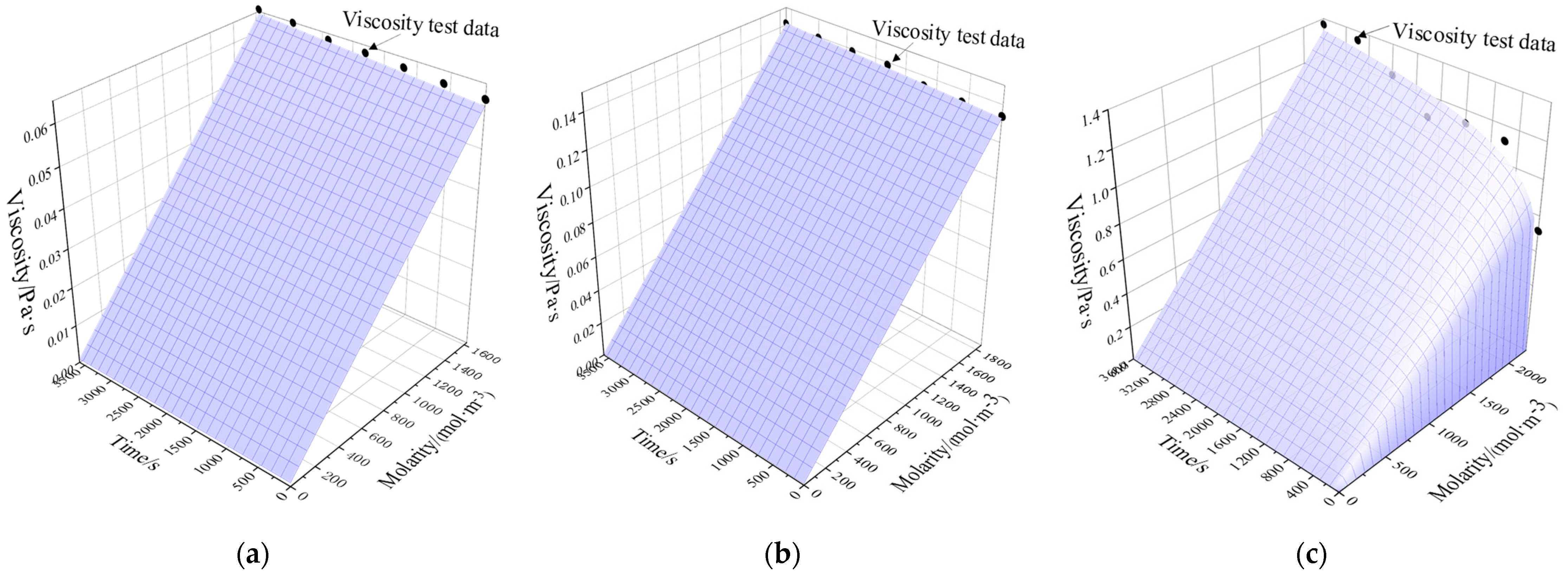
3, respectively (calculated according to the proportion of tricalcium silicate is 50%). An NDJ-5T rotational viscosimeter was adopted to test the time-varying data of viscosity, and the linear interpolation algorithm [
36] is adopted to drive the 3D surface functions of grouting material viscosity versus time and molarity:
where
is the viscosity of grouting material in Pa∙s;
t is time in s, ranging within 0–3600 s; and
c is the molarity of grouting material in mol/m
3, ranging within 0–1628 mol/m
3, 0–1864 mol/m
3, and 0–2234 mol/m
3, respectively. As shown in
Figure 1, 3D surface functions are plotted for the three cement grouting materials with distinct water–cement ratios.
- 2.
Variation of density with molarity during the migration of cement slurry
The molarity of the three cement slurries with different water–cement ratios are 1628 mol/m
3, 1864 mol/m
3, and 2234 mol/m
3, and the densities are 1485 kg/m
3, 1530 kg/m
3, and 1630 kg/m
3, respectively; the molarity of water is 0 mol/m
3 and the density is 1000 kg/m
3. Assume that the molarity of the slurry is proportional to the density; thus, the density of the three slurries can be expressed by the following equation.
2.1.2. Variation of Voids’ Seepage Parameters with Infiltration Pressure
During grouting process, the slurry infiltration pressure changes particle disposition spacing or manner of the geotechnical soil so that the actual physical parameters such as porosity and permeability change dynamically with the infiltration pressure, which further affects the infiltration process. When neglecting the temperature effect, the literature [
37] provides the following equations for the dynamic variation of the porosity of the geotechnical soil under the infiltration pressure and the dynamic variation of the soil permeability:
where
is dynamic porosity;
is dynamic permeability;
is the initial porosity;
is initial permeability;
is the volumetric strain;
(
is the initial pressure and
is the current pressure); and
is the bulk modulus of rocky soil.
Combining (1), (4), and (8) together; (2), (5), and (8) together; and (3), (6), and (8) together, respectively, one can build a model of variable permeability coefficient for grouting of the three cement grouts with distinct water–cement ratios:
where
is the permeability coefficient.
2.1.3. Flow and Mass Transfer Characteristics Control Equations
The grouting process of broken surrounding rock is a problem of slurry migration and substance conveyance through porous media, which is analyzed in the following details [
38].
The fluid flow control equation is expressed by Darcy law as follows:
where
is the porosity of the grouted medium;
is Darcy seepage flow velocity in m/s;
is the permeability of the grouted medium in m
2, dependent only on the solid’s skeleton structure;
is the fluid’s viscosity in Pa∙s;
is fluid pressure in Pa;
is the fluid’s density in kg/m
3;
is the unit vector in the direction of gravity; and
is the vertical coordinate.
- 2.
Basic Equation for Solute Migration
Provided that mere consideration is given to convection, molecular diffusion, and mechanical dispersion, the basic equation for solute migration is expressed as follows:
where
is the molarity of the i
th component in mol/m
3;
is the molecular diffusion coefficient in m
2/s; and
is the reaction rate of the i
th component in mol/(m
3∙s). Since cement hydration reaction rate is extremely low during the quiescent stage, the effect of cement hydration reaction on molarity of components is ignored;
is Darcy seepage flow velocity in m/s.
2.2. Engineering Background and Numerical Simulation
2.2.1. Engineering Background
Against the background of Xianglushan Tunnel for water diversion in central Yunnan Province, based on the foregoing analysis into the multi-field coupling mechanical mechanism, this paper elaborates the advance grouting migration law for tunnels with high-stress broken surrounding rocks with the help of COMSOL software. The main channel in the water diversion works in central Yunnan Province has a total length of 663.23 km, comprising outlet tunnels (92.03%), culverts with top-fill, aqueducts, inverted siphons, and other water conveyance structures [
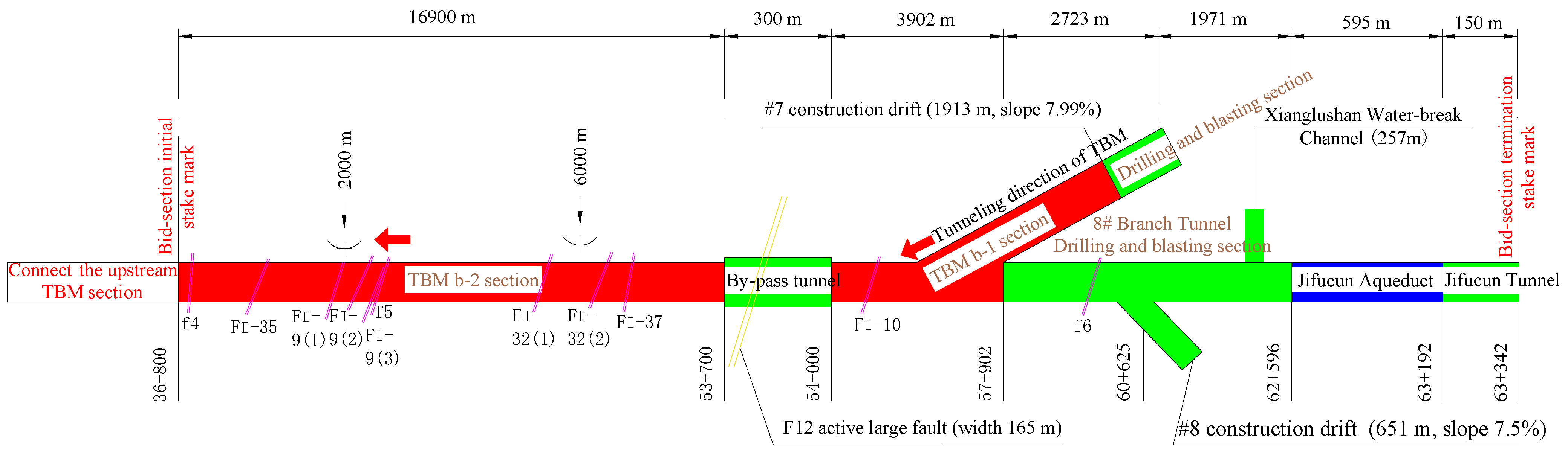
39]. Xianglushan Tunnel is the longest deep-buried tunnel in the water diversion works in central Yunnan Province, with a maximum burial depth of 1512 m and a total route length of 62.449 km. As shown in
Figure 2, the Xianglushan Tunnel is constructed by a mix of borehole blasting method and TBM method, and the segment tunneled by the latter method is 35.37 km long. According to exploratory design information, the downstream segment TBMb has large cross sections with tunneled diameters of 9.8 m and IV- and V-type surrounding rocks accounting for 53.14%; it passes across a total of 11 great fractured fault zones, among which F12 is characterized as a regional active large fracture with a fault breadth of 165 m. While tunneled ahead by TBM through the fractured fault zones and fold crushed zones, the strata ahead of the tunnel face are crushed and are extremely prone to being collapsed and destabilized; meanwhile, the fault fracture zone has a certain degree of hydraulic conductivity, which has the risk of generating larger-scale sudden water and mud surges. In the case that the tunneling machine becomes trapped and stuck in the TBM mode, it would be imperative to handle the situation by utilizing advance grouting reinforcement.
2.2.2. Numerical Model
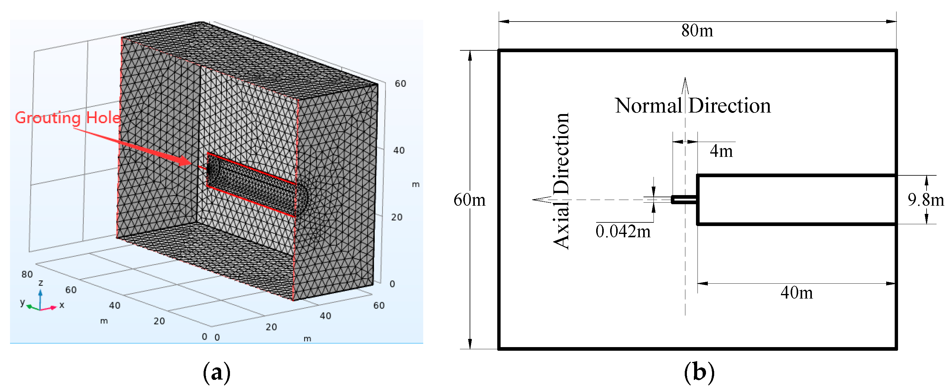
As shown in
Figure 3, the model size is 60 m × 80 m × 60 m, the tunnel diameter is 9.8 m, it is tunneled for 40 m, the grouting borehole diameter is 4.2 cm, and borehole’s length is 4 m. The calculation process falls into initial ground stress balancing, tunneling, and borehole grouting.
2.2.3. Model Parameter Values
Refer to the “Thematic Design Report on Xianglushan” for the parameter values in the numerical model. The exact values are shown in
Table 2.
3. Results and Discussions
3.1. Basic Law of Grouting Migration for Tunnels with High-Stress Broken Surrounding Rocks
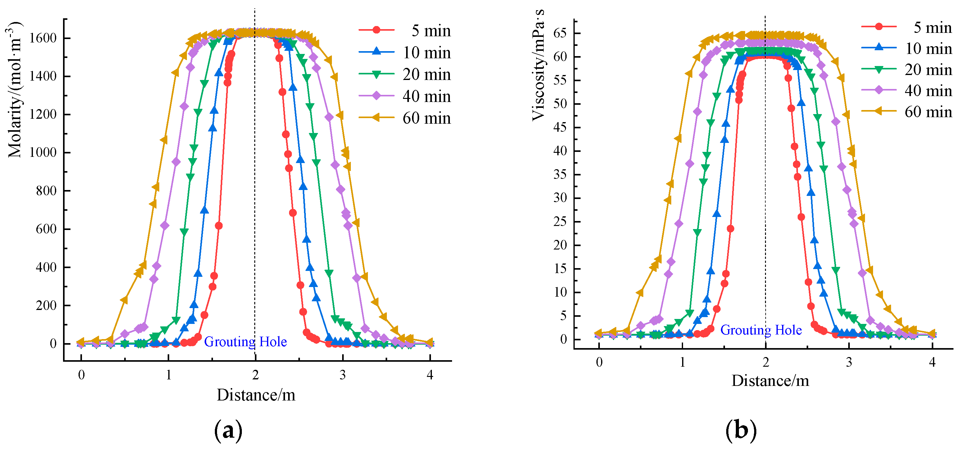
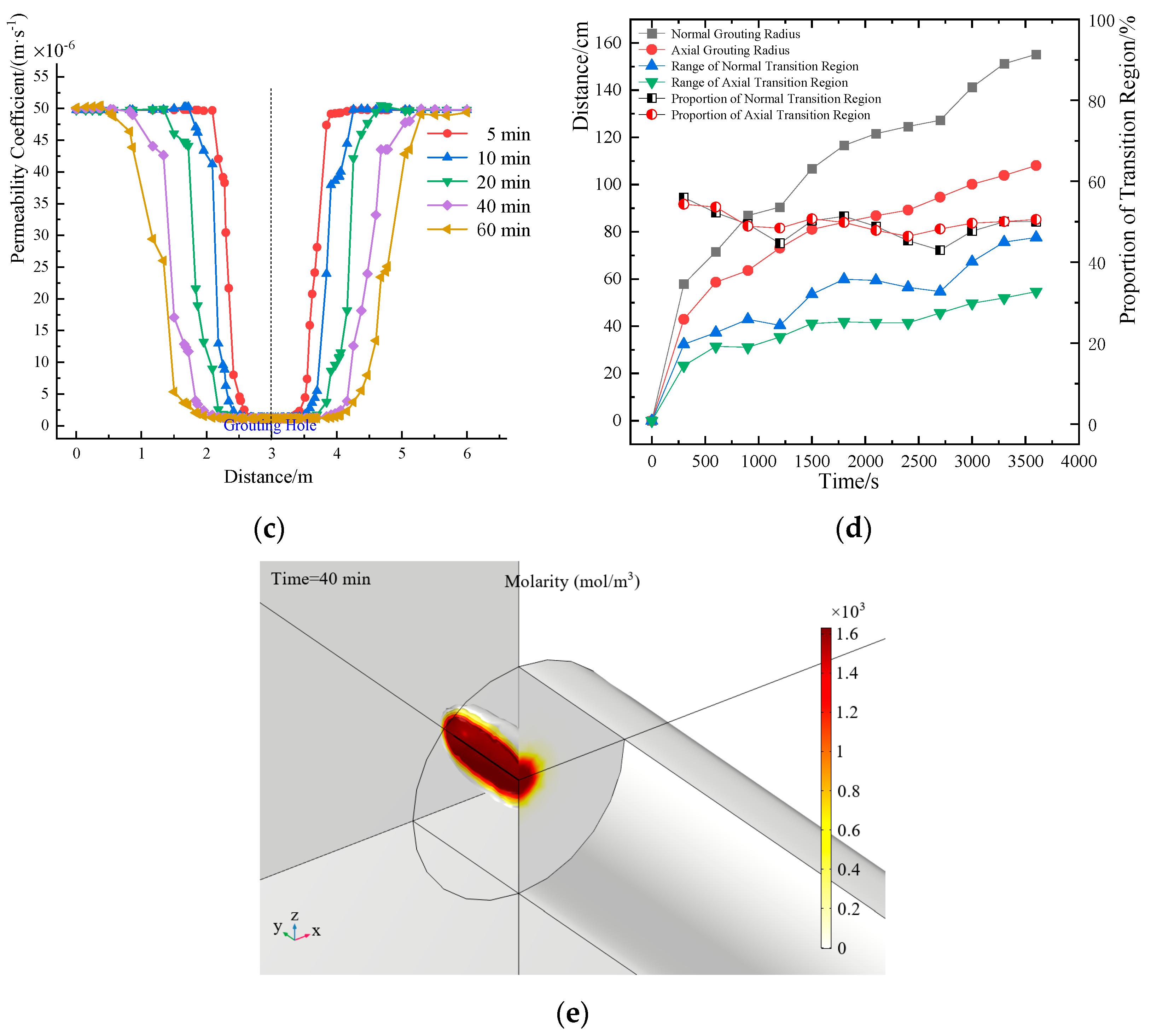
With the calculation model at a water–cement ratio of 1.0, initial permeability 5D, and grouting pressure 2 MPa as an example, a 10 meter-long monitoring line is set in the direction perpendicular to the grouting holes to analyze the cement grouting migration law. The grouting radius of grouting materials and the range of transition region at different times are calculated as shown in
Figure 4. There exists a certain transition region between grouting materials and underground water. Meanwhile, since viscosity and permeability coefficient are both dependent variables on molarity, 10% of the initial molarity (162.8 mol/m
3) of grouting materials can be taken as an indicator of permeation radius of grouting materials; 10%–95% of the initial molarity (162.8–1546.6 mol/m
3) of grouting materials is defined as the transition region; and 95%–100% of the initial molarity as the raw slurry region.
Over time, molarity within the raw slurry region basically remains unchanged, permeability coefficient changes slightly, and viscosity increases slowly; at the same moment, viscosity and molarity within the transition region decreases, while permeability coefficient increases, as the distance from the grouting holes increases. In addition, viscosity increases slowly until the quiescent stage of cement expires, which basically coincides with the indoor test. The normal grouting radius is greater than the axial grouting radius; normal grouting radius, axial grouting radius, and range of transition region increase over time, but the proportion of the transition region over the grouting range is basically steady.
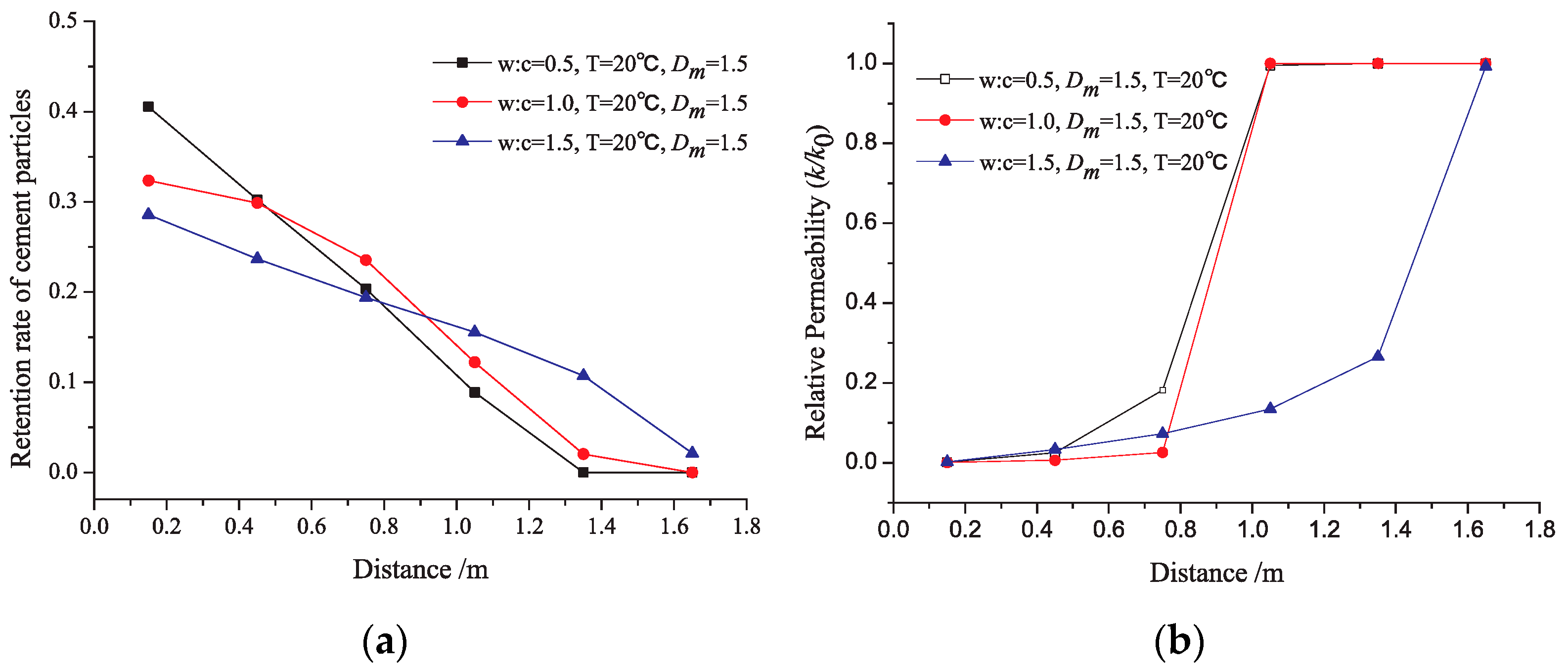
The indoor simulation test by Du X. et al. [
42] has confirmed the existence of transition region and concluded the similar law, as shown in
Figure 5. In the case of grouting amid porous media with the same fractal dimension of mass (i.e., the same porosity), for cement grouts with the same water–cement ratio, the retention rate of cement decreases and relative permeability increases with an increase in grouting migration distance.
While analyzing the influence characteristics of water–cement ratio, grouting pressure, and initial permeability on grouting migration law, the paragraphs below make a comparison with classical grouting theories in order to verify the applicability and reasonability of the model in this paper.
3.2. Influence Characteristics of Water–Cement Ratio on Grouting Migration Law
See Equations (13) and (14) for the cylindrical and spherical formulae for uniform migration of Newtonian fluids through a stratum [
43]. Theoretical grouting radius can be calculated with the parameter values in
Table 2:
where
is the grouting pressure head in cm;
is the migration radius of grouting materials in cm;
is the ratio of grouting material’s viscosity to water’s viscosity;
is the porosity of rocky soil; and
is the radius of grouting pipe in cm.
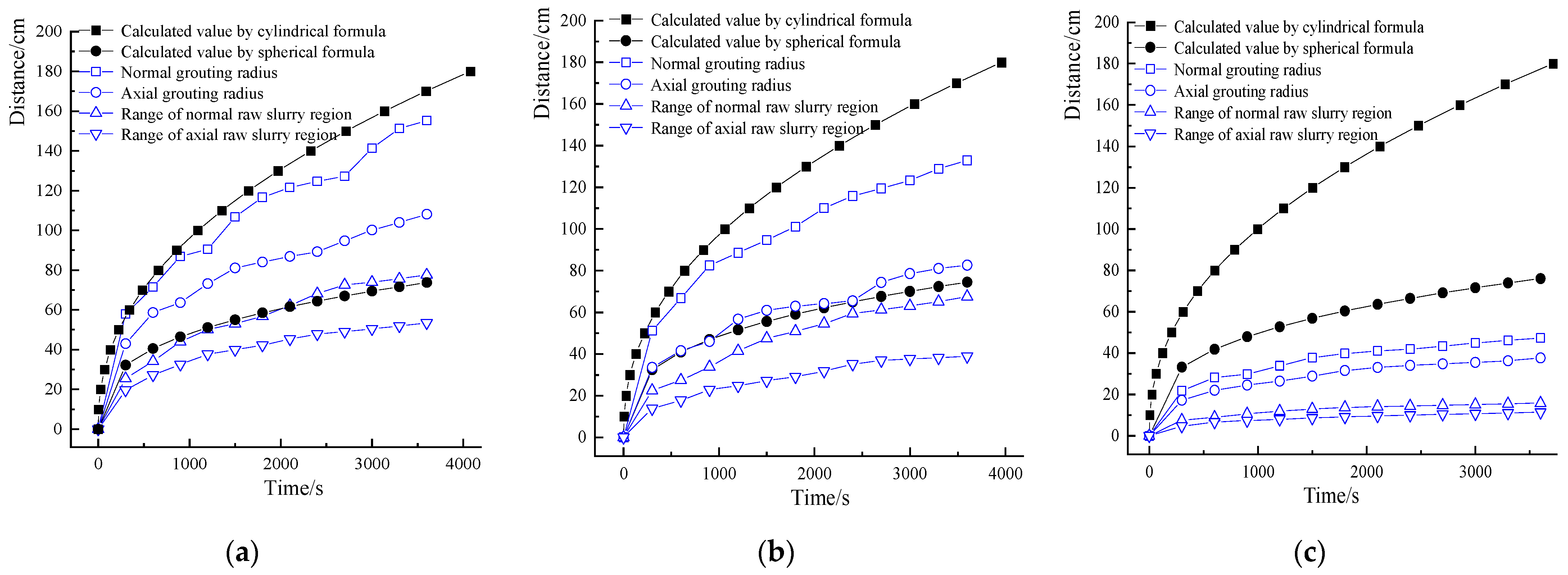
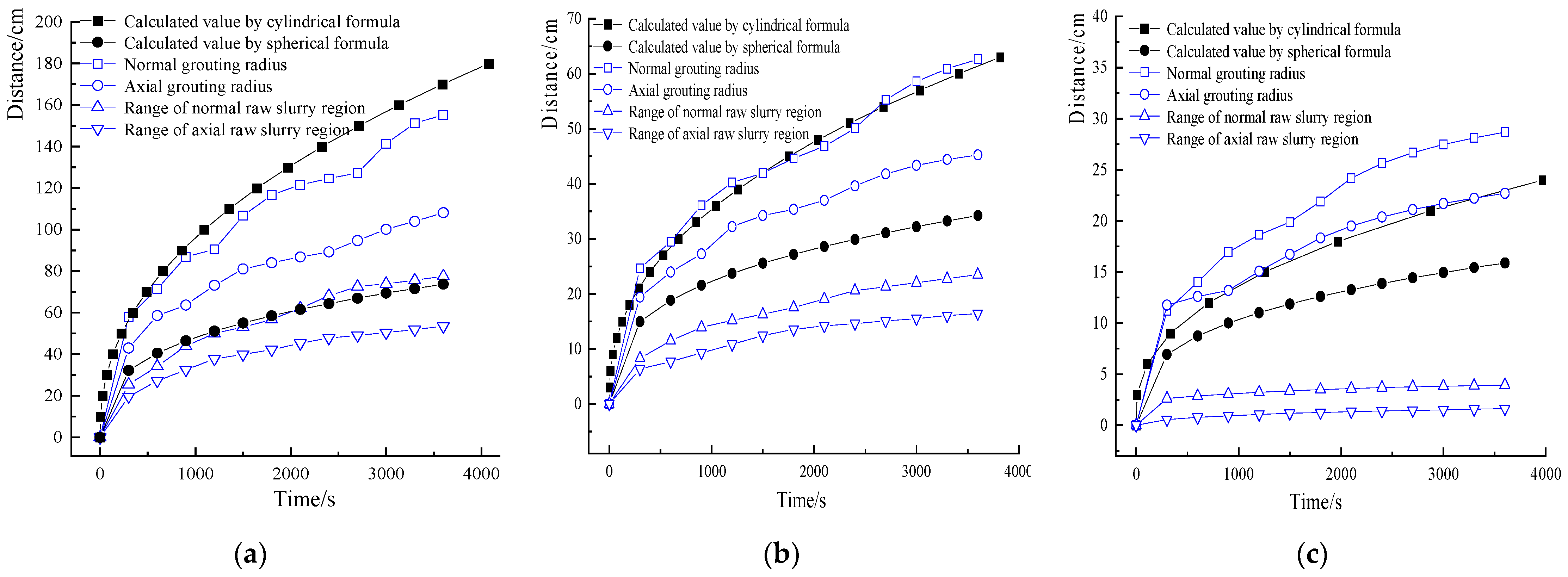
As shown in
Figure 6, the numerical models are calculated at water–cement ratios 1.0, 0.8, and 0.6, respectively, to analyze the influence characteristics of distinct water–cement ratios on grouting migration law at the same initial permeability 5D and grouting pressure 2 MPa. Overall, for the slurries with distinct water–cement ratios, the range of slurry migration enlarges gradually over time, and the growth rate is fast during the earlier 5 min and slows down later until the range of slurry migration tends to be steady. At the fifth minute, the normal grouting ranges are 22 cm, 51 cm, and 58 cm at water–cement ratios of 0.6, 0.8, and 1.0, respectively; at the 60th minute, the normal grouting ranges are 47 cm, 133 cm, and 155 cm at water–cement ratios 0.6, 0.8, and 1.0, respectively. At the same moment, the smaller the water–cement ratio of the slurry, the smaller the slurry’s migration range, since the viscosity of slurry increases in an order of magnitude as the water–cement ratio decreases, raising resistance to slurry migration. As the water–cement ratio decreases, the growth rates of normal and axial grouting radii and the range of raw slurry region decay gradually; grouting radius decreases dramatically at a water–cement ratio of 0.6, since the viscosity–time curve features a power function growth at this water–cement ratio and linear growths at water–cement ratios of 1.0 and 0.8; in addition, the viscosity–time growth rate increases as water–cement ratio decreases.
At the same moment, compared with the calculated values by classical grouting theories, the calculated values by the cylindrical formula are higher than the ones by the numerical model, and as water–cement ratio decreases, the deviation increases between the calculated values by the theoretical formula and the ones by the numerical model. At a water–cement ratio if 1.0, the calculated values by the spherical formula are overlapped with the range of normal raw slurry region. At a water–cement ratio of 0.8, the calculated values by the spherical formula are close to the axial grouting radius. At a water–cement ratio of 0.6, the calculated values by the spherical formula are higher than the ones by the numerical model. This shows that, at the operating condition of high water–cement ratios, the multi-field coupling mechanical model built in this paper can coincide better with the spherical formula. The variance between the calculated values from the classical theory and the ones from the numerical model resides mainly in the fact that the classical theory has overlooked the slurry’s viscosity–time characteristic—specifically, slurry viscosity increases more rapidly during the earlier 60 min than at a lower water–cement ratio.
3.3. Influence Characteristics of Grouting Pressure on Grouting Migration Law
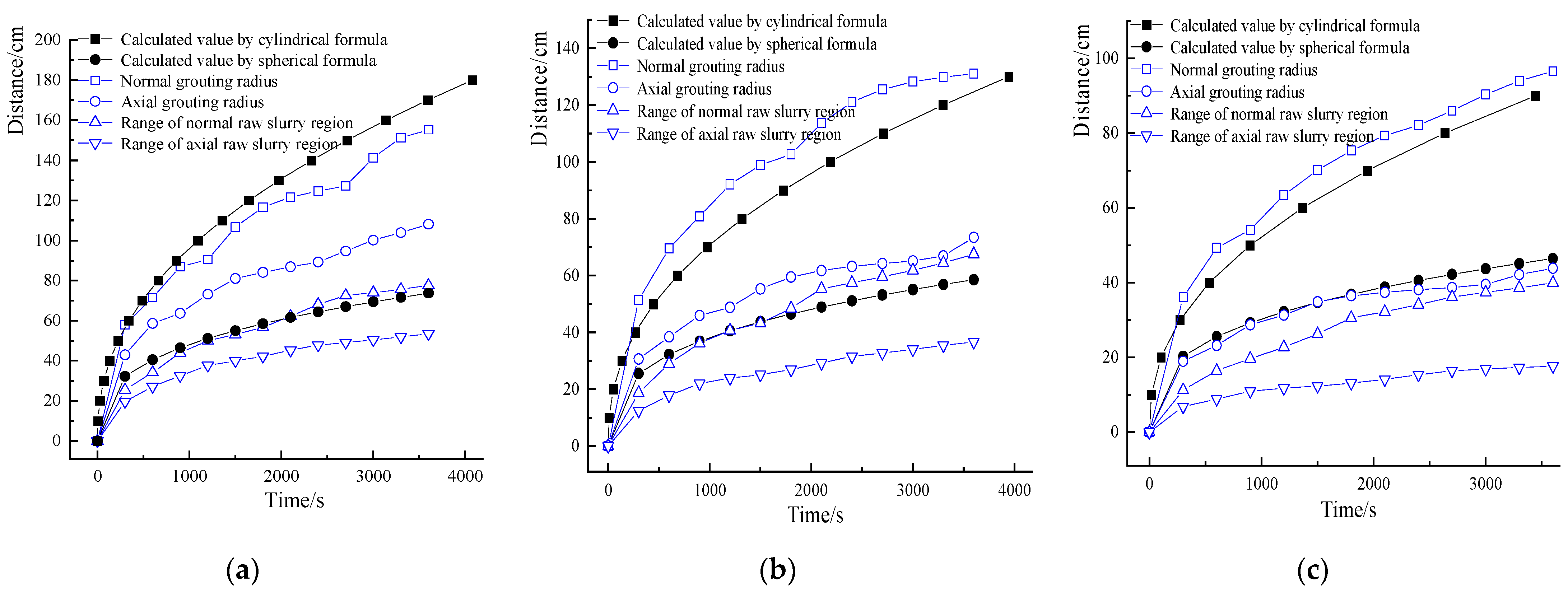
As shown in
Figure 7, the numerical models are calculated at grouting pressures 2 MPa, 1 MPa, and 0.5 MPa, respectively, to analyze the influence characteristics of distinct grouting pressures on grouting migration law at the same initial permeability 5D and a water–cement ratio of 1.0. Overall, for different grouting pressures, the range of slurry migration enlarges gradually over time, and the growth rate is fast during the earlier 5 min and slows down later until the range of slurry migration tends to be steady. At the fifth minute, the normal grouting ranges are 58 cm, 51 cm, and 36 cm at grouting pressures 2 MPa, 1 MPa, and 0.5 MPa, respectively; at the 60th minute, the normal grouting ranges are 155 cm, 131 cm, and 96 cm at grouting pressures 2 MPa, 1 MPa, and 0.5 MPa, respectively. At the same moment, the smaller the grouting pressure, the smaller the slurry migration range, and the growth rates of normal grouting radius, axial grouting radius, and range of raw slurry region decay gradually; as grouting pressure decreases, the power supplied for slurry migration decreases, causing difficulties to slurry migration and a decrease in grouting distance.
At the same moment, compared with the calculated values by the classical grouting theories related formulae, the calculated values by the cylindrical formula are higher than the normal grouting radius; in addition, with the decrease in grouting pressure, the calculated values by the cylindrical formula tend to be smaller than the normal grouting radius, but the results from the cylindrical formula are overall close to the normal grouting radius. At grouting pressure 2 MPa, the calculated values by the spherical formula are overlapped with the range of normal raw slurry region; at grouting pressure 1 MPa, the calculated values by the spherical formula become close to the normal raw slurry region; at grouting pressure 0.5 MPa, the calculated values by the spherical formula are overlapped with the normal raw slurry region. This shows that, at distinct grouting pressures, the multi-field coupling mechanical model built in this paper can coincide better with the spherical formula. From Equations (7) and (8), the increase in osmotic pressure may change the porosity, permeability, and other physical property parameters of the grouted medium. The variance between the calculated values from the classical theory and the ones from the numerical model resides mainly in the fact that the classical theory has overlooked the effects of the slurry’s viscosity–time characteristic and grouting pressure on the medium’s permeability parameters.
3.4. Influence Characteristics of Initial Permeability on Grouting Migration Law
As shown in
Figure 8, the numerical models are calculated at initial permeabilities 5D, 0.5D, and 0.05D, respectively, to analyze the influence characteristics of distinct initial permeabilities on grouting migration law at the same water–cement ratio 1.0 and grouting pressure of 2 MPa. Overall, the range of slurry migration enlarges gradually over time, and the growth rate is fast during the earlier 5 min and slows down later. At the fifth minute, the normal grouting ranges are 58 cm, 24 cm, and 11 cm at initial permeabilities 5D, 0.5D, and 0.05D, respectively; at the 60th minute, the normal grouting ranges are 155 cm, 63 cm, and 29 cm, at initial permeabilities 5D, 0.5D, and 0.05D, respectively. At the same moment, with the decrease in initial permeability, the slurry migration range shrinks, and the deviation of grouting radius increases from the range of raw slurry region, i.e., the range of transition region takes up an increasing proportion over grouting radius. Meanwhile, the growth rates of normal and axial grouting radii and range of raw slurry region decay gradually, since the decrease in initial permeability means a lower capacity in the grouted medium for slurry passage and, hence, a growing difficulty in slurry migration.
Compared with the calculated values by the classical grouting theories, at initial permeability 5D, the calculated values by the cylindrical formula are close to the normal grouting radius; at initial permeability 0.5D, the calculated values by the cylindrical formula coincide with the normal grouting radius. At initial permeability 0.05D, the calculated values by the cylindrical formula coincide with the axial grouting radius. This shows that the multi-field coupling mechanical model built in this paper can coincide better with the cylindrical formula; the variance between the calculated values from the classical theory and the ones from the numerical model resides mainly in the fact that the classical theory has overlooked the slurry’s viscosity–time characteristic.
4. Conclusions
By analyzing the multi-field coupling mechanism for advance grouting of cement slurry in tunnel with high-stress broken surrounding rocks, this paper has built a model of a variable permeability coefficient for tunnel grouting with simultaneous consideration of the dual changes of physical properties of grouting materials and surrounding rocks; elaborated the spatiotemporal evolution laws of viscosity, molarity, and permeability coefficient for the advanced grouting migration of cement grouting materials; revealed the influence characteristics of the water–cement ratio, grouting pressure, and initial permeability on grouting migration law; and verified the applicability and reasonability of the study in combination with classical grouting theories. The concrete conclusions are summarized as follows.
With the molarity of grouting materials as an indicator, the grouting radius has been divided into the raw slurry region and the transition region; overall, the grouting radius has zoomed during the earlier 5 min, and its growth rate has slowed down later. Over time, molarity within the raw slurry region basically remained unchanged, the permeability coefficient changed slightly, and viscosity increased slowly; with the increase in grouting distance, both viscosity and molarity within the transition region declined, whereas the permeability coefficient increased.
With the decrease in water–cement ratio, slurry molarity increased, slurry viscosity increased fast in a power function form at low water–cement ratios, while the grouting radius decreased, and the growth rates of normal and axial grouting radii also gradually decayed. With the decrease in grouting pressure, the grouting radius decreased, and the growth rates of normal and axial grouting radii gradually decayed. With the decrease in initial permeability, the grouting radius decreased, the proportion of the range of transition region over the grouting radius increased, and the magnitude of molarity gradient increased.
At the operating conditions of water–cement ratio being 1.0 and 0.8, respectively, the multi-field coupling mechanical model built in this paper can coincide better with the spherical formula; at grouting pressures 2 MPa, 1 MPa, and 0.5 MPa, the multi-field coupling mechanical model built in this paper can coincide better with the spherical formula. At initial permeabilities 5D, 0.5D, and 0.05D, the multi-field coupling mechanical model built in this study can coincide better with the cylindrical formula.
This study has made certain achievements in grouting migration modeling and law, except that the mathematical model for multi-field coupling grouting mechanism is suspected of being simplified. For example, failure to consider the percolation effect, hydration reaction, and other aspects of cement grouting materials would lead to a certain deviation of numerical simulation from the actual values. The next step will be to deepen the relevant study.
Author Contributions
Conceptualization, D.P.; methodology, D.P.; software, Z.Y. and Z.J.; investigation, S.Z.; resources, S.Z.; data curation, Z.J. and D.P.; writing—original draft preparation, Z.J. and D.P.; writing—review and editing, Z.Y. and J.Z. All authors have read and agreed to the published version of the manuscript.
Funding
This research was funded by National Natural Science Foundation of China (51874006, 52108365), China Postdoctoral Science Foundation (2020M683155), Natural Science Foundation of Henan Province of China (202300410001), Research and Development Program of China Railway Group Limited (2020-zhongdazhuanxiang-04-03), Science and Technology Innovation Program of China Railway Tunnel Group Co., Ltd. (Suiyanhe 2020-12), and Open Foundation of State Key Laboratory of Shield Machine and Boring Technology (SKLST-2019-K06).
Institutional Review Board Statement
Not applicable.
Informed Consent Statement
Not applicable.
Data Availability Statement
The data used in this study are available from the corresponding author upon request.
Conflicts of Interest
The authors declare no conflict of interest.
References
- He, M.C.; Xie, H.P.; Peng, S.P.; Jiang, Y.D. Study on rock mechanics in deep mining engineering. Chin. J. Rock Mech. Eng. 2005, 24, 2803–2813. [Google Scholar]
- Hong, K.R. Development and thinking of tunnels and underground engineering in China in recent 2 years (from 2017–2018). Tunn. Constr. 2019, 39, 710–723. [Google Scholar]
- Liu, Q.S.; Kang, Y.S.; Bai, Y.Q. Research on supporting method for deep rock roadway with broken and soft surrounding rock in Guqiao Coal Mine. Rock Soil Mech. 2011, 32, 3097–3104. [Google Scholar]
- Li, S.C.; Liu, R.T.; Zhang, Q.S.; Zhang, X. Protection against water or mud inrush in tunnels by grouting: A review. J. Rock Mech. Geotech. Eng. 2016, 8, 753–766. [Google Scholar] [CrossRef] [Green Version]
- Andjelkovic, V.; Lazarevic, Z.; Nedovic, V.; Stojanovic, Z. Application of the pressure grouting in the hydraulic tunnels. Tunn. Undergr. Space Technol. 2013, 37, 165–179. [Google Scholar] [CrossRef]
- Liu, X.L.; Wang, F.; Huang, J.; Wang, S.J.; Zhang, Z.Z.; Nawnit, K. Grout diffusion in silty fine sand stratum with high groundwater level for tunnel construction. Tunn. Undergr. Space Technol. 2019, 93, 103051. [Google Scholar] [CrossRef]
- Liu, J.; Zhang, Z.S.; Han, Y.; Wu, X. Backfilled grouting diffusion law and model of pressure on segments of shield tunnel considering viscosity variation of cement grout. Rock Soil Mech. 2015, 36, 361–368. [Google Scholar]
- Yang, Z.Q.; Niu, X.D.; Hou, K.P. Study of diffusion parameters of Bingham fluid based on column-hemispherical penetration grouting. J. Sichuan Univ. 2015, 47, 47–53. [Google Scholar]
- Zou, J.H.; Li, L.; Yang, X.L.; Wang, Z.B.; He, C.M. Method of energy analysis for compaction grouting. Yantu Lixue 2006, 27, 475–478. [Google Scholar]
- Zhang, Z.M.; Zou, J.; He, J.Y.; Lin, C.G. Cavity expansion theory of compaction grouting in saturated clay considering pressure filtration. J. Zhejiang Univ. 2011, 45, 1980–1984. [Google Scholar]
- Zhang, X.; Li, S.C.; Zhang, Q.S.; Sun, K.G.; Liu, R.T.; Han, W.W.; Yuan, X.S. Study of key-hole grouting method to harness high pressure water gushing in fractured rock mass. Chin. J. Rock Mech. Eng. 2011, 30, 1414–1421. [Google Scholar]
- Zhang, M.; Zou, J.F.; Chen, J.Q.; Li, L.; Li, Z.C. Analysis of soil fracturing grouting pressure under asymmetric loads. Rock Soil Mech. 2013, 34, 2255–2263. [Google Scholar]
- Zou, J.F.; Tong, W.Q.; Luo, H.; Wang, X.F. Mechanism of fracture grouting for fractured rock based on Hoek–Brown failure criterion. J. Cent. South Univ. 2013, 7, 2889–2896. [Google Scholar]
- Li, S.C.; Zhang, W.J.; Zhang, Q.S.; Zhang, X.; Liu, R.T.; Pan, G.M.; Li, Z.P.; Che, Z.Y. Research on advantage-fracture grouting mechanism and controlled grouting method in water-rich fault zone. Rock Soil Mech. 2014, 35, 744–752. [Google Scholar]
- Bai, J.B.; Wang, X.Y.; Wang, H.; Hou, C.J. Research on technology and mechanism of grouting by using high-moisture quick-concreting material. In Key Engineering Materials; Trans Tech Publications Ltd.: Zuerich, Switzerland, 2009; pp. 30–36. [Google Scholar]
- Zhang, B.; Gao, F.; Zhang, X.F.; Zhou, Y.F.; Hu, B.L.; Song, H.Y. Modified cement-sodium silicate material and grouting technology for repairing underground concrete structure cracks. Arab. J. Geosci. 2019, 12, 1–10. [Google Scholar] [CrossRef]
- Pan, D.J.; Hong, K.R.; Fu, H.L.; Zhou, J.J.; Zhang, N.; Lu, G.M. Influence characteristics and mechanism of fragmental size of broken coal mass on the injection regularity of silica sol grouting. Constr. Build. Mater. 2021, 269, 121251. [Google Scholar] [CrossRef]
- Sun, Z.D.; Zhang, J.X.; Sun, Y.N. Feasibility of a polymer foaming agent as a grouting material for broken coal masses. Adv. Civ. Eng. 2019, 4, 1–9. [Google Scholar] [CrossRef]
- Shi, Z.Y.; Wang, Q.B.; Xu, L. Experimental Study of Cement Alkali-Resistant Glass Fiber (C-ARGF) Grouting Material. Materials 2020, 13, 605. [Google Scholar] [CrossRef] [Green Version]
- Yang, P.; Liu, Y.H.; Gao, S.W.; Xue, S.B. Experimental investigation on the diffusion of carbon fibre composite grouts in rough fractures with flowing water. Tunn. Undergr. Space Technol. 2020, 95, 103146. [Google Scholar] [CrossRef]
- Hou, F.J.; Sun, K.G.; Wu, Q.D.; Xu, W.P.; Ren, S.J. Grout diffusion model in porous media considering the variation in viscosity with time. Adv. Mech. Eng. 2019, 11, 1687814018819890. [Google Scholar] [CrossRef] [Green Version]
- Cheng, H.; Liu, X.Y.; Lin, J.; Zhang, L.L.; Li, M.J.; Rong, C.X. Study on Fracturing and Diffusion Mechanism of Nonslab Fracturing Grouting. Geofluids 2020, 2020, 8838135. [Google Scholar] [CrossRef]
- Zhu, H.X.; Han, L.J.; Meng, Q.B.; Liu, J.; Meng, L.D.; Dong, W.L. The split-permeation grouting mechanism of loose and broken coal rock masses considering the temporal and spatial characteristics of slurry viscosity. KSCE J. Civ. Eng. 2021, 25, 1887–1900. [Google Scholar] [CrossRef]
- Niu, J.D.; Wang, B.; Feng, C.; Chen, K. Experimental Research on Viscosity Characteristics of Grouting Slurry in a High Ground Temperature Environment. Materials 2020, 13, 3221. [Google Scholar] [CrossRef] [PubMed]
- Zhu, Z.J.; Wang, M.; Liu, R.T.; Zhang, H.S.; Zhang, C.Y.; Liu, Y.K.; Bai, J.W.; Zhang, L.Z. Study of the viscosity-temperature characteristics of cement-sodium silicate grout considering the time-varying behaviour of viscosity. Constr. Build. Mater. 2021, 306, 124818. [Google Scholar] [CrossRef]
- Zhang, C.; Yang, J.S.; Xie, Y.P.; Dai, Y.; Liang, X.; Gong, F.H. Distribution characteristics of grouting reinforcement ring for tunnel with heterogeneous weak surrounding rock. J. Traffic Transp. Eng. 2019, 19, 58–70. [Google Scholar]
- Pan, D.J.; Hong, K.R.; Fu, H.L.; Li, Z.G.; Zhang, L.M.; Lu, G.M.; Sun, F.X.; Wen, S.Y. Numerical Simulation of Nanosilica Sol Grouting for Deep Tunnels Based on the Multifield Coupling Mechanism. Geofluids 2021, 2021, 3963291. [Google Scholar] [CrossRef]
- Pan, D.J.; Hong, K.R.; Fu, H.L.; Zhou, J.J.; Zhang, N. Experimental study of the mechanism of grouting colloidal nano-silica in over-broken coal mass. Q. J. Eng. Geol. Hydrogeol. 2021, 54, qjegh2020-161. [Google Scholar] [CrossRef]
- Zheng, W.H.; Wang, D.W.; Li, G.J.; Qin, L.; Luo, K.; Liu, J.Q. Optimizing the grouting design for groundwater inrush control in completely weathered granite tunnel: An experimental and field investigation. Sustainability 2019, 11, 3636. [Google Scholar] [CrossRef] [Green Version]
- Liu, J.Q.; Yuen, K.V.; Chen, W.Z.; Zhou, X.S. Grouting for water and mud inrush control in weathered granite tunnel: A case study. Eng. Geol. 2020, 279, 105896. [Google Scholar] [CrossRef]
- Bai, J.W.; Li, S.C.; Jiang, Y.J.; Liu, R.T.; Li, Z.F.; Li, W. An extension theoretical model for grouting effect evaluation in sand stratum of metro construction. KSCE J. Civ. Eng. 2019, 23, 2349–2358. [Google Scholar] [CrossRef]
- Yang, J.Y.; Cheng, Y.H.; Chen, W.C. Experimental study on diffusion law of post-grouting slurry in sandy soil. Adv. Civ. Eng. 2019, 12, 1–11. [Google Scholar] [CrossRef] [Green Version]
- Sha, F.; Lin, C.J.; Li, Z.F.; Liu, R.T. Reinforcement simulation of water-rich and broken rock with Portland cement-based grout. Constr. Build. Mater. 2019, 221, 292–300. [Google Scholar] [CrossRef]
- Scrivener, K.; Ouzia, A.; Juilland, P.; Mohamed, A.K. Advances in understanding cement hydration mechanisms. Cem. Concr. Res. 2019, 124, 105823. [Google Scholar] [CrossRef]
- Marchon, D.; Flatt, R.J. 8—Mechanisms of cement hydration. In Science and Technology of Concrete Admixtures; Aïtcin, P.-C., Flatt, R.J., Eds.; Woodhead Publishing: Cambridge, UK, 2016; pp. 129–145. [Google Scholar]
- Koyama, T.; Katayama, T.; Tanaka, T.; Kuzuha, Y.; Ohnishi, Y. Development of a numerical model for grout injection and its application to the in situ grouting test at the Grimsel test site, Switzerland. Geosystem Eng. 2013, 16, 26–36. [Google Scholar] [CrossRef]
- Cheng, P.D.; Lu, L.; Ju, T.; Wang, D.Z. Application of time-varying viscous grout in gravel-foundation anti-seepage treatment. J. Hydrodyn. Ser. B 2011, 23, 391–397. [Google Scholar] [CrossRef]
- Wu, W.X.; Gong, F.Q.; Yang, W.M. Experimental simulation study of spalling in deep rectangular tunnel with plastic fine grain marble. Tunn. Undergr. Space Technol. 2020, 98, 103319. [Google Scholar] [CrossRef]
- Zhao, Y. The Most Representative National Key Water Conservancy Project under Construction: Central Yunnan Water Diversion Project. Tunn. Constr. 2019, 39, 511–522. [Google Scholar]
- Potapov, V.; Povarov, K.; Podverbny, V.; Guseva, O. Study of colloidal silica formation and precipitation in solution of Mutnovskoe hydrothermal field (Kamchatka, Russia). In Proceedings of the World Geothermal Congress 2005, Antalya, Turkey, 24–29 April 2005; pp. 1–9. [Google Scholar]
- Weggel, J.R.; Gallagher, P.; Lin, Y.Z. Analytical model for transport of dilute colloidal silica dispersions through porous media. J. Geotech. Geoenvironmental Eng. 2018, 144, 04018082. [Google Scholar] [CrossRef]
- Zhou, Z.L.; Cai, X.; Du, X.M.; Wang, S.Y.; Ma, D.; Zang, H.Z. Strength and filtration stability of cement grouts in porous media. Tunn. Undergr. Space Technol. 2019, 89, 1–9. [Google Scholar] [CrossRef]
- Kuang, J.Z.; Zan, Y.W.; Wang, J.; Du, J.H. Grouting Theory and Engineering Examples of Rock and Soil; Science Press: Beijing, China, 2001. [Google Scholar]
| Publisher’s Note: MDPI stays neutral with regard to jurisdictional claims in published maps and institutional affiliations. |
© 2022 by the authors. Licensee MDPI, Basel, Switzerland. This article is an open access article distributed under the terms and conditions of the Creative Commons Attribution (CC BY) license (https://creativecommons.org/licenses/by/4.0/).


