Luminescent Metal–Organic Framework Thin Films: From Preparation to Biomedical Sensing Applications


Abstract
:1. Introduction
2. Methods for the Fabrication of MOF Thin Films
2.1. Deposition from Solvothermal Mother Solutions
2.1.1. In Situ Growth
2.1.2. Seed-Assisted Growth
2.2. Electrochemical Synthesis
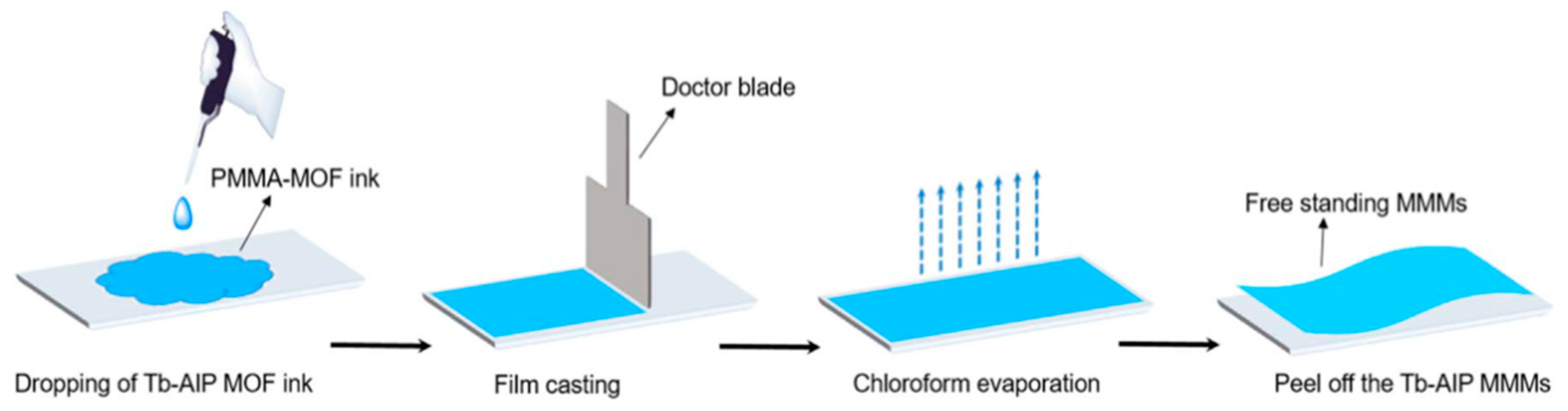
2.3. Mixed Matrix Membranes
3. Luminescence Behavior in MOF Thin Films
3.1. Lanthanide Luminescence
3.2. Ligand-Based Luminescence
3.3. Luminescence Generated from Guest Molecules
4. Biomedical Sensing Application of Luminescent MOF thin Films
4.1. Temperature Sensing
4.2. Ion Detection
4.2.1. Cu2+ Sensing
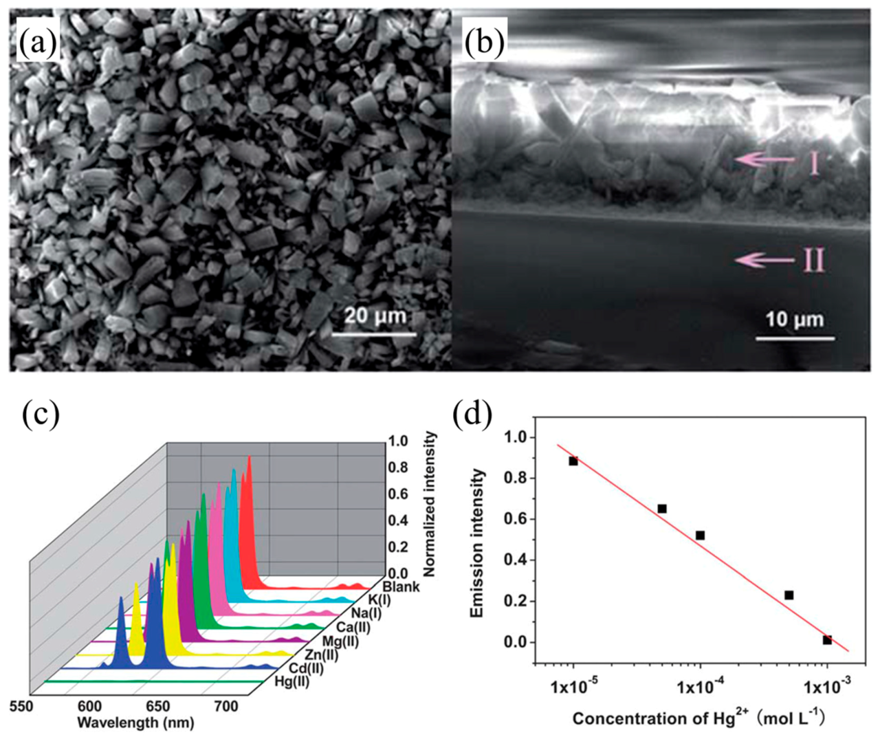
4.2.2. Hg2+ Sensing
4.2.3. Cr3+ Sensing
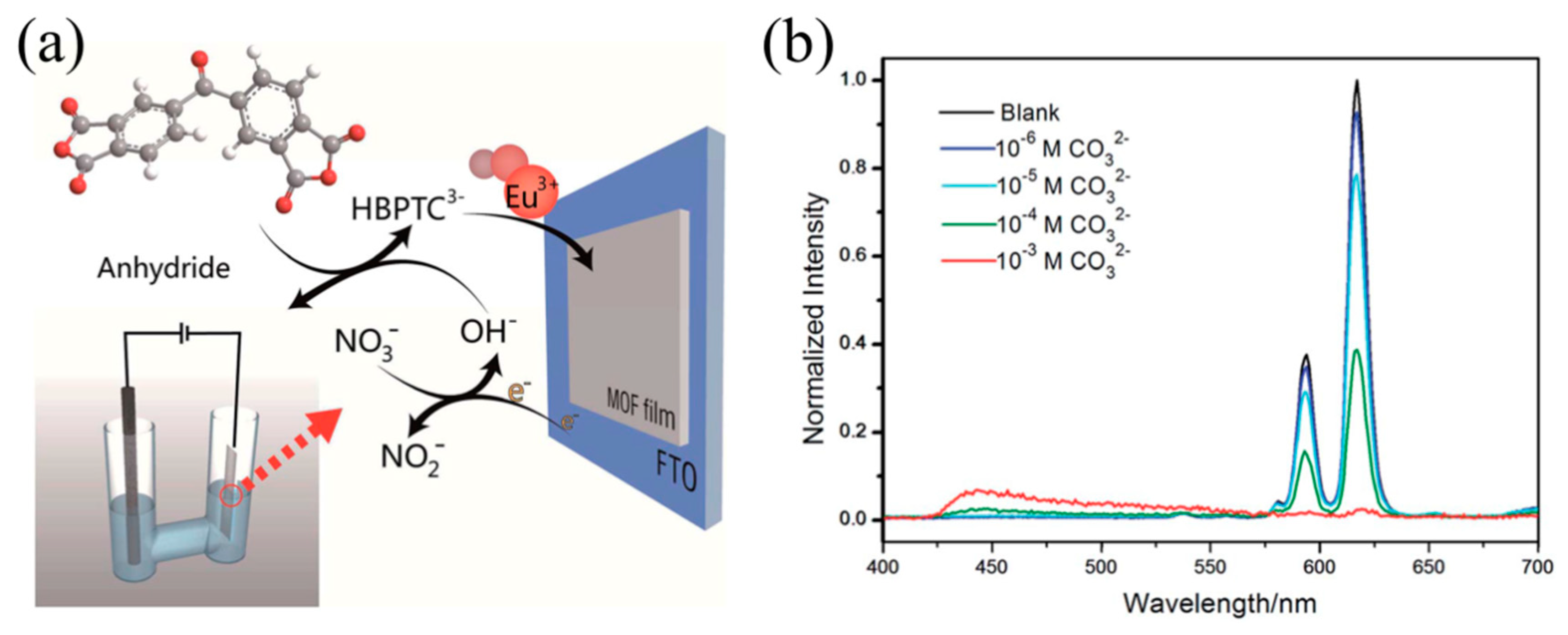
4.2.4. CO32− Sensing
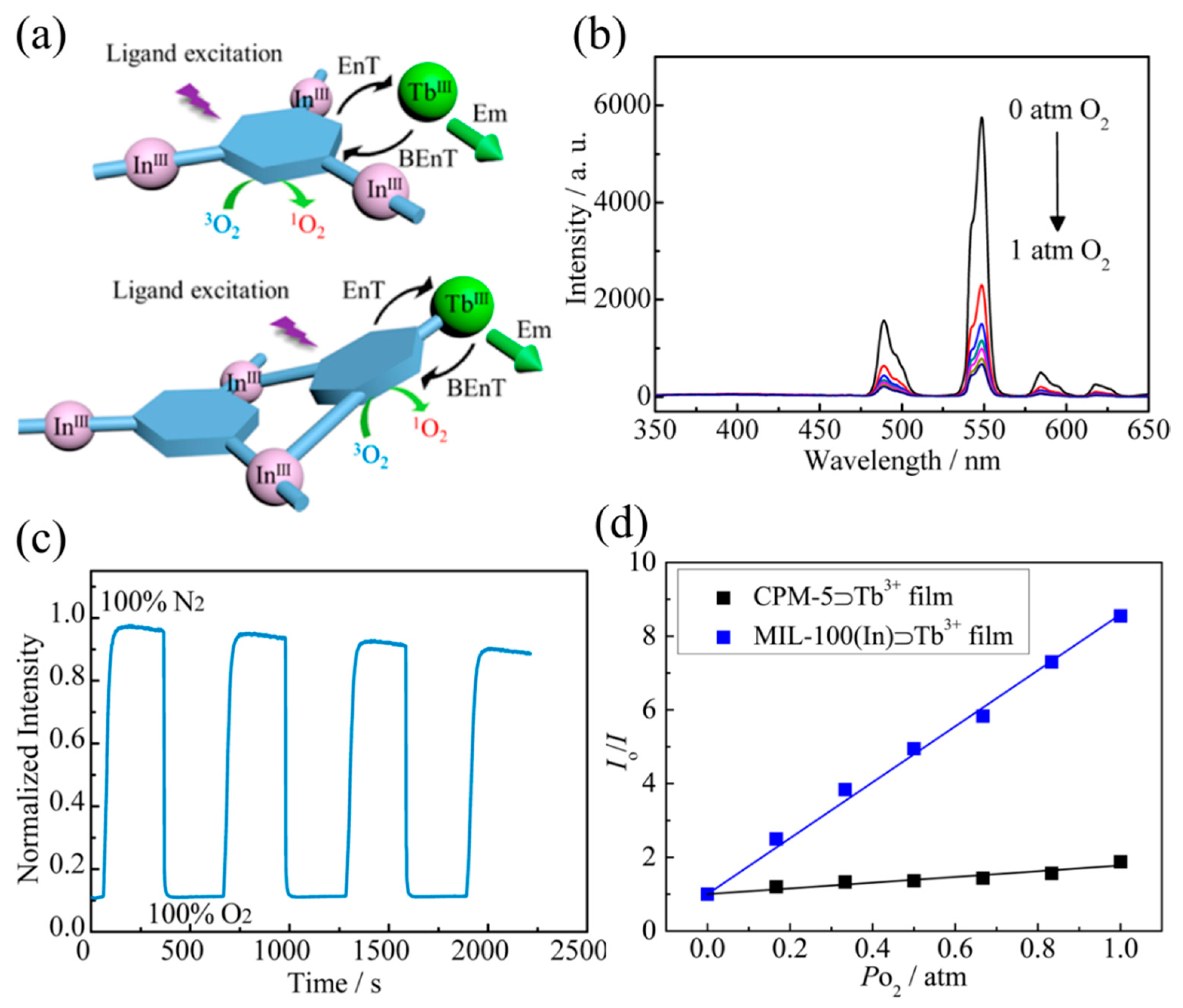
4.3. Gas Detection
4.4. Biomolecule Detection
4.4.1. Formaldehyde
4.4.2. Pharmaceuticals
4.4.3. Nitrofuran Antibiotics
5. Conclusions and Outlook
Author Contributions
Funding
Conflicts of Interest
References
- Kirsch, J.; Siltanen, C.; Zhou, Q.; Revzin, A.; Simonian, A. Biosensor technology: Recent advances in threat agent detection and medicine. Chem. Soc. Rev. 2013, 42, 8733–8768. [Google Scholar] [CrossRef] [PubMed]
- Turner, A.P.F. Biosensors: Sense and sensibility. Chem. Soc. Rev. 2013, 42, 3184–3196. [Google Scholar] [CrossRef] [PubMed]
- Wang, X.-D.; Wolfbeis, O.S.; Meier, R.J. Luminescent probes and sensors for temperature. Chem. Soc. Rev. 2013, 42, 7834–7869. [Google Scholar] [CrossRef] [PubMed]
- Wang, H.-S. Metal–organic frameworks for biosensing and bioimaging applications. Coord. Chem. Rev. 2017, 349, 139–155. [Google Scholar] [CrossRef]
- Pramanik, S.; Zheng, C.; Zhang, X.; Emge, T.J.; Li, J. New Microporous Metal−Organic Framework Demonstrating Unique Selectivity for Detection of High Explosives and Aromatic Compounds. J. Am. Chem. Soc. 2011, 133, 4153–4155. [Google Scholar] [CrossRef] [PubMed]
- Zhang, K.; Zhou, H.; Mei, Q.; Wang, S.; Guan, G.; Liu, R.; Zhang, J.; Zhang, Z. Instant visual detection of trinitrotoluene particulates on various surfaces by ratiometric fluorescence of dual-emission quantum dots hybrid. J. Am. Chem. Soc. 2011, 133, 8424–8427. [Google Scholar] [CrossRef] [PubMed]
- You, L.; Zha, D.; Anslyn, E.V. Recent advances in supramolecular analytical chemistry using optical sensing. Chem. Rev. 2015, 115, 7840–7892. [Google Scholar] [CrossRef] [PubMed]
- Shanmugaraju, S.; Mukherjee, P.S. π-Electron rich small molecule sensors for the recognition of nitroaromatics. Chem. Commun. 2015, 51, 16014–16032. [Google Scholar] [CrossRef] [PubMed]
- Ding, S.-Y.; Dong, M.; Wang, Y.-W.; Chen, Y.-T.; Wang, H.-Z.; Su, C.-Y.; Wang, W. Thioether-Based Fluorescent Covalent Organic Framework for Selective Detection and Facile Removal of Mercury(II). J. Am. Chem. Soc. 2016, 138, 3031–3037. [Google Scholar] [CrossRef] [PubMed]
- Shi, W.; Li, X.; Ma, H. A tunable ratiometric pH sensor based on carbon nanodots for the quantitative measurement of the intracellular pH of whole cells. Angew. Chem. Int. Ed. 2012, 124, 6538–6541. [Google Scholar] [CrossRef]
- Feng, J.; Tian, K.; Hu, D.; Wang, S.; Li, S.; Zeng, Y.; Li, Y.; Yang, G. A Triarylboron-Based Fluorescent Thermometer: Sensitive Over a Wide Temperature Range. Angew. Chem. Int. Ed. 2011, 50, 8072–8076. [Google Scholar] [CrossRef] [PubMed]
- Chen, Z.; Zhang, K.Y.; Tong, X.; Liu, Y.; Hu, C.; Liu, S.; Yu, Q.; Zhao, Q.; Huang, W. Phosphorescent Polymeric Thermometers for In Vitro and In Vivo Temperature Sensing with Minimized Background Interference. Adv. Funct. Mater. 2016, 46, 4386–4396. [Google Scholar] [CrossRef]
- Miyata, K.; Konno, Y.; Nakanishi, T.; Kobayashi, A.; Kato, M.; Fushimi, K.; Hasegawa, Y. Chameleon Luminophore for Sensing Temperatures: Control of Metal-to-Metal and Energy Back Transfer in Lanthanide Coordination Polymers. Angew. Chem. Int. Ed. 2013, 52, 6413–6416. [Google Scholar] [CrossRef] [PubMed]
- Kalytchuk, S.; Polakova, K.; Wang, Y.; Froning, J.P.; Cepe, K.; Rogach, A.L.; Zboril, R. Carbon Dot Nanothermometry: Intracellular Photoluminescence Lifetime Thermal Sensing. ACS Nano 2017, 11, 1432–1442. [Google Scholar] [CrossRef] [PubMed]
- Guan, W.; Zhou, W.; Lu, J.; Lu, C. Luminescent films for chemo- and biosensing. Chem. Soc. Rev. 2015, 44, 6981–7009. [Google Scholar] [CrossRef] [PubMed]
- Liu, J.; Sun, F.; Zhang, F.; Wang, Z.; Zhang, R.; Wang, C.; Qiu, S. In situ growth of continuous thin metal–organic framework film for capacitive humidity sensing. J. Mater. Chem. 2011, 21, 3775–3778. [Google Scholar] [CrossRef]
- Stassen, I.; Burtch, N.; Talin, A.; Falcaro, P.; Allendorf, M.; Ameloot, R. An updated roadmap for the integration of metal–organic frameworks with electronic devices and chemical sensors. Chem. Soc. Rev. 2017, 46, 3185–3241. [Google Scholar] [CrossRef] [PubMed]
- Cui, Y.; Song, R.; Yu, J.; Liu, M.; Wang, Z.; Wu, C.; Yang, Y.; Wang, Z.; Chen, B.; Qian, G. Dual-Emitting MOF⊃Dye Composite for Ratiometric Temperature Sensing. Adv. Mater. 2015, 27, 1420–1425. [Google Scholar] [CrossRef] [PubMed]
- Miller, S.E.; Teplensky, M.H.; Moghadam, P.Z.; Fairen-Jimenez, D. Metal–organic frameworks as biosensors for luminescence-based detection and imaging. Interface Focus 2016, 6, 20160027. [Google Scholar] [CrossRef] [PubMed]
- Xu, X.Y.; Lian, X.; Hao, J.N.; Zhang, C.; Yan, B. A Double-Stimuli-Responsive Fluorescent Center for Monitoring of Food Spoilage based on Dye Covalently Modified EuMOFs: From Sensory Hydrogels to Logic Devices. Adv. Mater. 2017, 29, 1702298. [Google Scholar] [CrossRef] [PubMed]
- Lin, R.-B.; Li, F.; Liu, S.-Y.; Qi, X.-L.; Zhang, J.-P.; Chen, X.-M. A Noble-Metal-Free Porous Coordination Framework with Exceptional Sensing Efficiency for Oxygen. Angew. Chem. Int. Ed. 2013, 52, 13429–13433. [Google Scholar] [CrossRef] [PubMed]
- Nagarkar, S.S.; Joarder, B.; Chaudhari, A.K.; Mukherjee, S.; Ghosh, S.K. Highly Selective Detection of Nitro Explosives by a Luminescent Metal–Organic Framework. Angew. Chem. Int. Ed. 2013, 52, 2881–2885. [Google Scholar] [CrossRef] [PubMed]
- Hu, Z.; Deibert, B.J.; Li, J. Luminescent metal–organic frameworks for chemical sensing and explosive detection. Chem. Soc. Rev. 2014, 43, 5815–5840. [Google Scholar] [CrossRef] [PubMed]
- Wang, B.; Lv, X.-L.; Feng, D.; Xie, L.-H.; Zhang, J.; Li, M.; Xie, Y.; Li, J.-R.; Zhou, H.-C. Highly Stable Zr(IV)-Based Metal–Organic Frameworks for the Detection and Removal of Antibiotics and Organic Explosives in Water. J. Am. Chem. Soc. 2016, 138, 6204–6216. [Google Scholar] [CrossRef] [PubMed]
- Xia, T.; Zhu, F.; Cui, Y.; Yang, Y.; Wang, Z.; Qian, G. Highly selective luminescent sensing of picric acid based on a water-stable europium metal-organic framework. J. Solid State Chem. 2017, 245, 127–131. [Google Scholar] [CrossRef]
- Zhang, L.-N.; Liu, A.-L.; Liu, Y.-X.; Shen, J.-X.; Du, C.-X.; Hou, H.-W. A luminescent europium metal–organic framework with free phenanthroline sites for highly selective and sensitive sensing of Cu2+ in aqueous solution. Inorg. Chem. Commun. 2015, 56, 137–140. [Google Scholar] [CrossRef]
- Xu, X.-Y.; Yan, B. Intelligent Molecular Searcher from Logic Computing Network Based on Eu(III) Functionalized UMOFs for Environmental Monitoring. Adv. Funct. Mater. 2017, 27, 1700247. [Google Scholar] [CrossRef]
- Xia, T.; Cui, Y.; Yang, Y.; Qian, G. Highly Stable Mixed-Lanthanide Metal–Organic Frameworks for Self-Referencing and Colorimetric Luminescent pH Sensing. ChemNanoMat 2017, 3, 51–57. [Google Scholar] [CrossRef]
- Zhang, S.-Y.; Shi, W.; Cheng, P.; Zaworotko, M.J. A Mixed-Crystal Lanthanide Zeolite-like Metal–Organic Framework as a Fluorescent Indicator for Lysophosphatidic Acid, a Cancer Biomarker. J. Am. Chem. Soc. 2015, 137, 12203–12206. [Google Scholar] [CrossRef] [PubMed]
- Hao, J.-N.; Yan, B. Determination of Urinary 1-Hydroxypyrene for Biomonitoring of Human Exposure to Polycyclic Aromatic Hydrocarbons Carcinogens by a Lanthanide-functionalized Metal-Organic Framework Sensor. Adv. Funct. Mater. 2017, 27, 1603856. [Google Scholar] [CrossRef]
- Wu, S.; Lin, Y.; Liu, J.; Shi, W.; Yang, G.; Cheng, P. Rapid Detection of the Biomarkers for Carcinoid Tumors by a Water Stable Luminescent Lanthanide Metal–Organic Framework Sensor. Adv. Funct. Mater. 2018, 28, 1707169. [Google Scholar] [CrossRef]
- Li, B.; Wen, H.-M.; Cui, Y.; Qian, G.; Chen, B. Multifunctional lanthanide coordination polymers. Prog. Polym. Sci. 2015, 48, 40–84. [Google Scholar] [CrossRef]
- Xia, T.; Song, T.; Cui, Y.; Yang, Y.; Qian, G. A dye encapsulated terbium-based metal-organic framework for ratiometric temperature sensing. Dalton Trans. 2016, 45, 18689–18695. [Google Scholar] [CrossRef] [PubMed]
- Lustig, W.P.; Mukherjee, S.; Rudd, N.D.; Desai, A.V.; Li, J.; Ghosh, S.K. Metal–organic frameworks: Functional luminescent and photonic materials for sensing applications. Chem. Soc. Rev. 2017, 46, 3242–3285. [Google Scholar] [CrossRef] [PubMed]
- Yan, B. Lanthanide-Functionalized Metal-Organic Framework Hybrid Systems To Create Multiple Luminescent Centers for Chemical Sensing. Acc. Chem. Res. 2017, 50, 2789–2798. [Google Scholar] [CrossRef] [PubMed]
- Cui, Y.; Li, B.; He, H.; Zhou, W.; Chen, B.; Qian, G. Metal–Organic Frameworks as Platforms for Functional Materials. Acc. Chem. Res. 2016, 49, 483–493. [Google Scholar] [CrossRef] [PubMed]
- Kreno, L.E.; Leong, K.; Farha, O.K.; Allendorf, M.; Van Duyne, R.P.; Hupp, J.T. Metal-organic framework materials as chemical sensors. Chem. Rev. 2012, 112, 1105–1125. [Google Scholar] [CrossRef] [PubMed]
- Zhang, Y.; Yuan, S.; Day, G.; Wang, X.; Yang, X.; Zhou, H.-C. Luminescent sensors based on metal–organic frameworks. Coord. Chem. Rev. 2017, 354, 28–45. [Google Scholar] [CrossRef]
- Zacher, D.; Shekhah, O.; Wöll, C.; Fischer, R.A. Thin films of metal–organic frameworks. Chem. Soc. Rev. 2009, 38, 1418–1429. [Google Scholar] [CrossRef] [PubMed]
- Yao, J.; Wang, H. Zeolitic imidazolate framework composite membranes and thin films: Synthesis and applications. Chem. Soc. Rev. 2014, 43, 4470–4493. [Google Scholar] [CrossRef] [PubMed]
- Liu, J.; Woll, C. Surface-supported metal-organic framework thin films: Fabrication methods, applications, and challenges. Chem. Soc. Rev. 2017, 46, 5730–5770. [Google Scholar] [CrossRef] [PubMed]
- Falcaro, P.; Ricco, R.; Doherty, C.M.; Liang, K.; Hill, A.J.; Styles, M.J. MOF positioning technology and device fabrication. Chem. Soc. Rev. 2014, 43, 5513–5560. [Google Scholar] [CrossRef] [PubMed] [Green Version]
- Shekhah, O.; Liu, J.; Fischer, R.A.; Woll, C. MOF thin films: Existing and future applications. Chem. Soc. Rev. 2011, 40, 1081–1106. [Google Scholar] [CrossRef] [PubMed]
- Bradshaw, D.; Garai, A.; Huo, J. Metal-organic framework growth at functional interfaces: Thin films and composites for diverse applications. Chem. Soc. Rev. 2012, 41, 2344–2381. [Google Scholar] [CrossRef] [PubMed]
- Qiu, S.; Xue, M.; Zhu, G. Metal-organic framework membranes: From synthesis to separation application. Chem. Soc. Rev. 2014, 43, 6116–6140. [Google Scholar] [CrossRef] [PubMed]
- Zhuang, J.-L.; Terfort, A.; Wöll, C. Formation of oriented and patterned films of metal–organic frameworks by liquid phase epitaxy: A review. Coord. Chem. Rev. 2016, 307, 391–424. [Google Scholar] [CrossRef]
- Liu, Y.; Ng, Z.; Khan, E.A.; Jeong, H.-K.; Ching, C.-B.; Lai, Z. Synthesis of continuous MOF-5 membranes on porous α-alumina substrates. Micropor. Mesopor. Mater. 2009, 118, 296–301. [Google Scholar] [CrossRef]
- Zacher, D.; Baunemann, A.; Hermes, S.; Fischer, R.A. Deposition of microcrystalline [Cu3(btc)2] and [Zn2(bdc)2(dabco)] at alumina and silica surfaces modified with patterned self assembled organic monolayers: Evidence of surface selective and oriented growth. J. Mater. Chem. 2007, 17, 2785–2792. [Google Scholar] [CrossRef]
- Shah, M.; Kwon, H.T.; Tran, V.; Sachdeva, S.; Jeong, H.-K. One step in situ synthesis of supported zeolitic imidazolate framework ZIF-8 membranes: Role of sodium formate. Micropor. Mesopor. Mater. 2013, 165, 63–69. [Google Scholar] [CrossRef]
- Bux, H.; Chmelik, C.; van Baten, J.M.; Krishna, R.; Caro, J. Novel MOF-membrane for molecular sieving predicted by IR-diffusion studies and molecular modeling. Adv. Mater. 2010, 22, 4741–4743. [Google Scholar] [CrossRef] [PubMed]
- Eslava, S.; Zhang, L.; Esconjauregui, S.; Yang, J.; Vanstreels, K.; Baklanov, M.R.; Saiz, E. Metal-organic framework ZIF-8 films as low-κ dielectrics in microelectronics. Chem. Mater. 2012, 25, 27–33. [Google Scholar] [CrossRef]
- Guo, H.; Zhu, G.; Hewitt, I.J.; Qiu, S. “Twin copper source” growth of metal–organic framework membrane: Cu3(BTC)2 with high permeability and selectivity for recycling H2. J. Am. Chem. Soc. 2009, 131, 1646–1647. [Google Scholar] [CrossRef] [PubMed]
- Zou, X.; Zhu, G.; Hewitt, I.J.; Sun, F.; Qiu, S. Synthesis of a metal–organic framework film by direct conversion technique for VOCs sensing. Dalton Trans. 2009, 3009–3013. [Google Scholar] [CrossRef] [PubMed]
- Kayaert, S.; Bajpe, S.; Masschaele, K.; Breynaert, E.; Kirschhock, C.E.; Martens, J.A. Direct growth of Keggin polyoxometalates incorporated copper 1,3,5-benzenetricarboxylate metal organic framework films on a copper metal substrate. Thin Solid Films 2011, 519, 5437–5440. [Google Scholar] [CrossRef]
- Kang, Z.; Xue, M.; Fan, L.; Ding, J.; Guo, L.; Gao, L.; Qiu, S. “Single nickel source” in situ fabrication of a stable homochiral MOF membrane with chiral resolution properties. Chem. Commun. 2013, 49, 10569–10571. [Google Scholar] [CrossRef] [PubMed]
- Huang, A.; Dou, W.; Caro, J. Steam-stable zeolitic imidazolate framework ZIF-90 membrane with hydrogen selectivity through covalent functionalization. J. Am. Chem. Soc. 2010, 132, 15562–15564. [Google Scholar] [CrossRef] [PubMed]
- Huang, A.; Bux, H.; Steinbach, F.; Caro, J. Molecular-sieve membrane with hydrogen permselectivity: ZIF-22 in LTA topology prepared with 3-aminopropyltriethoxysilane as covalent linker. Angew. Chem. Int. Ed. 2010, 49, 4958–4961. [Google Scholar] [CrossRef] [PubMed]
- Arnold, M.; Kortunov, P.; Jones, D.J.; Nedellec, Y.; Kärger, J.; Caro, J. Oriented crystallisation on supports and anisotropic mass transport of the metal-organic framework manganese formate. Eur. J. Inorg. Chem. 2007, 2007, 60–64. [Google Scholar] [CrossRef]
- Cao, F.; Zhang, C.; Xiao, Y.; Huang, H.; Zhang, W.; Liu, D.; Zhong, C.; Yang, Q.; Yang, Z.; Lu, X. Helium recovery by a Cu-BTC metal-organic-framework membrane. Ind. Eng. Chem. Res. 2012, 51, 11274–11278. [Google Scholar] [CrossRef]
- So, M.C.; Jin, S.; Son, H.J.; Wiederrecht, G.P.; Farha, O.K.; Hupp, J.T. Layer-by-layer fabrication of oriented porous thin films based on porphyrin-containing metal–organic frameworks. J. Am. Chem. Soc. 2013, 135, 15698–15701. [Google Scholar] [CrossRef] [PubMed]
- Betard, A.; Fischer, R.A. Metal-organic framework thin films: From fundamentals to applications. Chem. Rev. 2012, 112, 1055–1083. [Google Scholar] [CrossRef] [PubMed]
- Zhang, J.; Xia, T.; Zhao, D.; Cui, Y.; Yang, Y.; Qian, G. In situ secondary growth of Eu(III)-organic framework film for fluorescence sensing of sulfur dioxide. Sensor. Actuat. B-Chem. 2018, 260, 63–69. [Google Scholar] [CrossRef]
- Yusenko, K.; Meilikhov, M.; Zacher, D.; Wieland, F.; Sternemann, C.; Stammer, X.; Ladnorg, T.; Wöll, C.; Fischer, R.A. Step-by-step growth of highly oriented and continuous seeding layers of [Cu2(ndc)2(dabco)] on bare oxide and nitride substrates. CrystEngComm 2010, 12, 2086–2090. [Google Scholar] [CrossRef]
- Yoo, Y.; Jeong, H.-K. Heteroepitaxial Growth of Isoreticular Metal–Organic Frameworks and Their Hybrid Films. Cryst. Growth Des. 2010, 10, 1283–1288. [Google Scholar] [CrossRef]
- Falcaro, P.; Okada, K.; Hara, T.; Ikigaki, K.; Tokudome, Y.; Thornton, A.W.; Hill, A.J.; Williams, T.; Doonan, C.; Takahashi, M. Centimetre-scale micropore alignment in oriented polycrystalline metal-organic framework films via heteroepitaxial growth. Nat. Mater. 2017, 16, 342–348. [Google Scholar] [CrossRef] [PubMed]
- Mueller, U.; Puetter, H.; Hesse, M.; Schubert, M.; Wessel, H.; Huff, J.; Guzmann, M. Method for Electrochemical Production of a Crystalline Porous Metal Organic Skeleton Material. U.S. Patent 7,968,739B2, 28 June 2011. [Google Scholar]
- Li, W.-J.; Tu, M.; Cao, R.; Fischer, R.A. Metal–organic framework thin films: Electrochemical fabrication techniques and corresponding applications & perspectives. J. Mater. Chem. A 2016, 4, 12356–12369. [Google Scholar]
- Alizadeh, S.; Nematollahi, D. Electrochemically Assisted Self-Assembly Technique for the Fabrication of Mesoporous Metal-Organic Framework Thin Films: Composition of 3D Hexagonally Packed Crystals with 2D Honeycomb-like Mesopores. J. Am. Chem. Soc. 2017, 139, 4753–4761. [Google Scholar] [CrossRef] [PubMed]
- Ameloot, R.; Stappers, L.; Fransaer, J.; Alaerts, L.; Sels, B.F.; De Vos, D.E. Patterned growth of metal-organic framework coatings by electrochemical synthesis. Chem. Mater. 2009, 21, 2580–2582. [Google Scholar] [CrossRef]
- Li, W.-J.; Lü, J.; Gao, S.-Y.; Li, Q.-H.; Cao, R. Electrochemical preparation of metal–organic framework films for fast detection of nitro explosives. J. Mater. Chem. A 2014, 2, 19473–19478. [Google Scholar] [CrossRef]
- Campagnol, N.; Van Assche, T.; Boudewijns, T.; Denayer, J.; Binnemans, K.; De Vos, D.; Fransaer, J. High pressure, high temperature electrochemical synthesis of metal–organic frameworks: Films of MIL-100(Fe) and HKUST-1 in different morphologies. J. Mater. Chem. A 2013, 1, 5827–5830. [Google Scholar] [CrossRef]
- Li, W.-J.; Liu, J.; Sun, Z.-H.; Liu, T.-F.; Lü, J.; Gao, S.-Y.; He, C.; Cao, R.; Luo, J.-H. Integration of metal–organic frameworks into an electrochemical dielectric thin film for electronic applications. Nat. Commun. 2016, 7, 11830. [Google Scholar] [CrossRef] [PubMed]
- Hod, I.; Bury, W.; Karlin, D.M.; Deria, P.; Kung, C.W.; Katz, M.J.; So, M.; Klahr, B.; Jin, D.; Chung, Y.W. Directed growth of electroactive metal-organic framework thin films using electrophoretic deposition. Adv. Mater. 2014, 26, 6295–6300. [Google Scholar] [CrossRef] [PubMed]
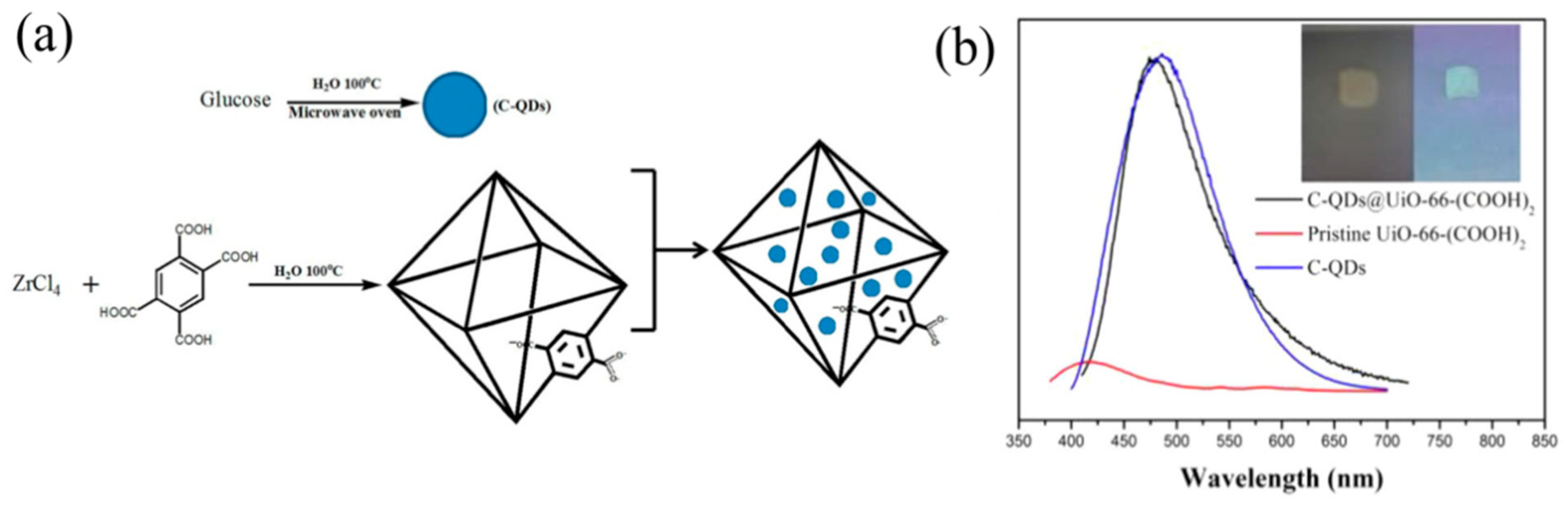
- Feng, J.F.; Gao, S.Y.; Shi, J.; Liu, T.F.; Cao, R. C-QDs@UiO-66-(COOH)2 Composite Film via Electrophoretic Deposition for Temperature Sensing. Inorg. Chem. 2018, 57, 2447–2454. [Google Scholar] [CrossRef] [PubMed]
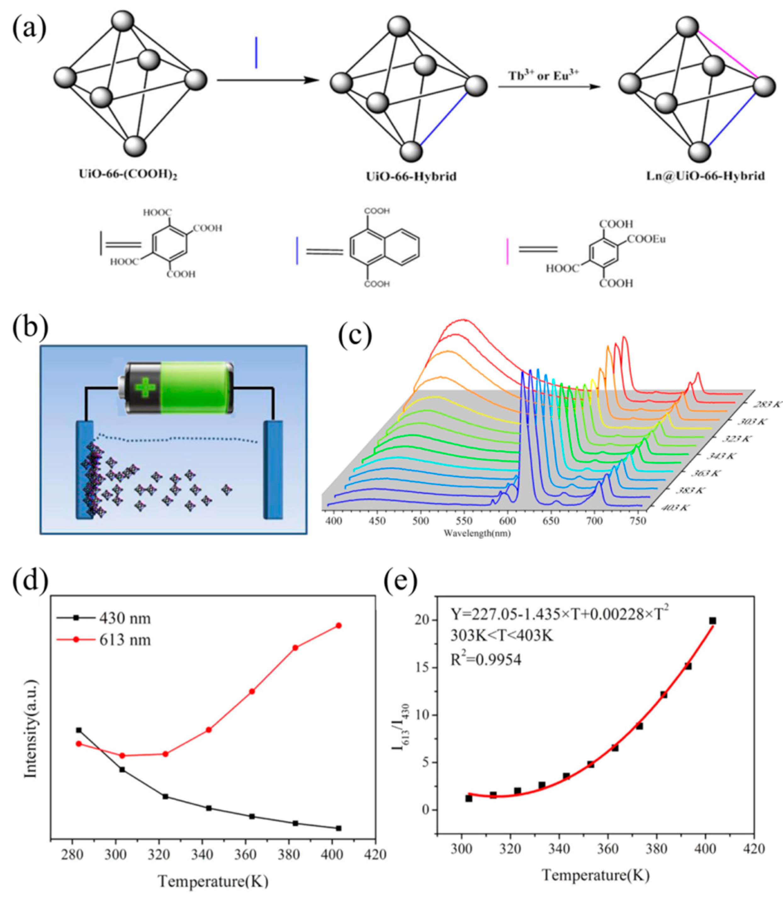
- Feng, J.F.; Gao, S.Y.; Liu, T.F.; Shi, J.; Cao, R. Preparation of Dual-Emitting Ln@UiO-66-Hybrid Films via Electrophoretic Deposition for Ratiometric Temperature Sensing. ACS Appl. Mater. Interfaces 2018, 10, 6014–6023. [Google Scholar] [CrossRef] [PubMed]
- Li, M.; Dincă, M. Selective formation of biphasic thin films of metal–organic frameworks by potential-controlled cathodic electrodeposition. Chem. Sci. 2014, 5, 107–111. [Google Scholar] [CrossRef] [Green Version]
- Liu, H.; Wang, H.; Chu, T.; Yu, M.; Yang, Y. An electrodeposited lanthanide MOF thin film as a luminescent sensor for carbonate detection in aqueous solution. J. Mater. Chem. C 2014, 2, 8683–8690. [Google Scholar] [CrossRef]
- Chernikova, V.; Shekhah, O.; Eddaoudi, M. Advanced Fabrication Method for the Preparation of MOF Thin Films: Liquid-Phase Epitaxy Approach Meets Spin Coating Method. ACS Appl. Mater. Interfaces 2016, 8, 20459–20464. [Google Scholar] [CrossRef] [PubMed]
- Guo, H.; Zhu, Y.; Qiu, S.; Lercher, J.A.; Zhang, H. Coordination Modulation Induced Synthesis of Nanoscale Eu1-xTbx-Metal–Organic Frameworks for Luminescent Thin Films. Adv. Mater. 2010, 22, 4190–4192. [Google Scholar] [CrossRef] [PubMed]
- Demessence, A.; Horcajada, P.; Serre, C.; Boissiere, C.; Grosso, D.; Sanchez, C.; Ferey, G. Elaboration and properties of hierarchically structured optical thin films of MIL-101(Cr). Chem. Commun. 2009, 7149–7151. [Google Scholar] [CrossRef] [PubMed]
- Jiang, D.; Burrows, A.D.; Xiong, Y.; Edler, K.J. Facile synthesis of crack-free metal–organic framework films on alumina by a dip-coating route in the presence of polyethylenimine. J. Mater. Chem. A 2013, 1, 5497–5500. [Google Scholar] [CrossRef] [Green Version]
- Yehia, H.; Pisklak, T.; Ferraris, J.; Balkus, K.; Musselman, I. Methane facilitated transport using copper(II) biphenyl dicarboxylate-triethylenediamine/poly (3-acetoxyethylthiophene) mixed matrix membranes. Abstr. Pap. Am. Chem. Soc. 2004, 227, U351. [Google Scholar]
- Campbell, J.; Székely, G.; Davies, R.P.; Braddock, D.C.; Livingston, A.G. Fabrication of hybrid polymer/metal organic framework membranes: Mixed matrix membranes versus in situ growth. J. Mater. Chem. A 2014, 2, 9260–9271. [Google Scholar] [CrossRef]
- Zornoza, B.; Tellez, C.; Coronas, J.; Gascon, J.; Kapteijn, F. Metal-organic framework based mixed matrix membranes: An increasingly important field of research with a large application potential. Micropor. Mesopor. Mater. 2013, 166, 67–78. [Google Scholar] [CrossRef]
- Liu, X.; Wang, C.; Wang, B.; Li, K. Novel Organic-Dehydration Membranes Prepared from Zirconium Metal–Organic Frameworks. Adv. Funct. Mater. 2017, 27, 1604311. [Google Scholar] [CrossRef]
- Seoane, B.; Coronas, J.; Gascon, I.; Etxeberria Benavides, M.; Karvan, O.; Caro, J.; Kapteijn, F.; Gascon, J. Metal-organic framework based mixed matrix membranes: A solution for highly efficient CO2 capture? Chem. Soc. Rev. 2015, 44, 2421–2454. [Google Scholar] [CrossRef] [PubMed] [Green Version]
- Denny, M.S., Jr.; Cohen, S.M. In Situ Modification of Metal–Organic Frameworks in Mixed-Matrix Membranes. Angew. Chem. Int. Ed. 2015, 54, 9029–9032. [Google Scholar] [CrossRef] [PubMed]
- Cui, Y.; Yue, Y.; Qian, G.; Chen, B. Luminescent functional metal–organic frameworks. Chem. Rev. 2012, 112, 1126–1162. [Google Scholar] [CrossRef] [PubMed]
- Cui, Y.; Chen, B.; Qian, G. Lanthanide metal–organic frameworks for luminescent sensing and light-emitting applications. Coord. Chem. Rev. 2014, 273, 76–86. [Google Scholar] [CrossRef]
- Zhang, F.; Zhang, G.; Yao, H.; Wang, Y.; Chu, T.; Yang, Y. A europium(III) based nano-flake MOF film for efficient fluorescent sensing of picric acid. Microchim. Acta 2017, 184, 1207–1213. [Google Scholar] [CrossRef]
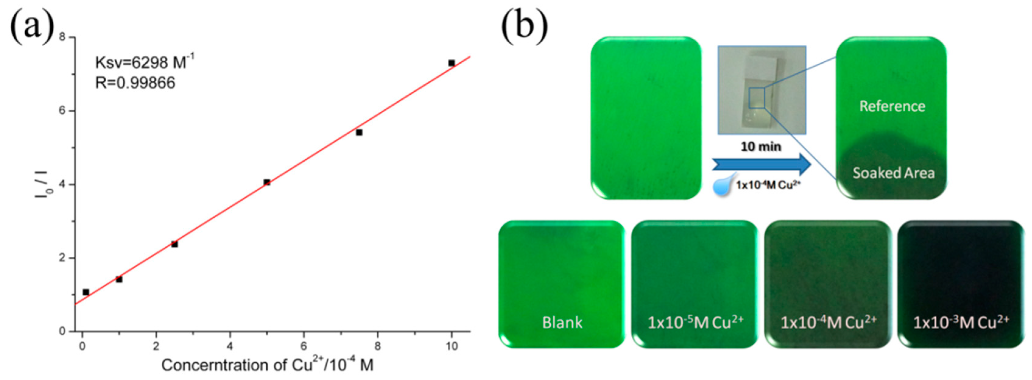
- Wang, Z.; Liu, H.; Wang, S.; Rao, Z.; Yang, Y. A luminescent Terbium-Succinate MOF thin film fabricated by electrodeposition for sensing of Cu2+ in aqueous environment. Sens. Actuators B-Chem. 2015, 220, 779–787. [Google Scholar] [CrossRef]
- Gao, Y.; Yu, G.; Liu, K.; Wang, B. Luminescent mixed-crystal Ln-MOF thin film for the recognition and detection of pharmaceuticals. Sens. Actuators B-Chem. 2018, 257, 931–935. [Google Scholar] [CrossRef]
- Liu, H.; Chu, T.; Rao, Z.; Wang, S.; Yang, Y.; Wong, W.-T. The Tunable White-Light and Multicolor Emission in An Electrodeposited Thin Film of Mixed Lanthanide Coordination Polymers. Adv. Opt. Mater. 2015, 3, 1545–1550. [Google Scholar] [CrossRef]
- Dou, Z.; Yu, J.; Cui, Y.; Yang, Y.; Wang, Z.; Yang, D.; Qian, G. Luminescent Metal–Organic Framework Films As Highly Sensitive and Fast-Response Oxygen Sensors. J. Am. Chem. Soc. 2014, 136, 5527–5530. [Google Scholar] [CrossRef] [PubMed]
- Zhang, J.; Yue, D.; Xia, T.; Cui, Y.; Yang, Y.; Qian, G. A luminescent metal-organic framework film fabricated on porous Al2O3 substrate for sensitive detecting ammonia. Micropor. Mesopor. Mater. 2017, 253, 146–150. [Google Scholar] [CrossRef]
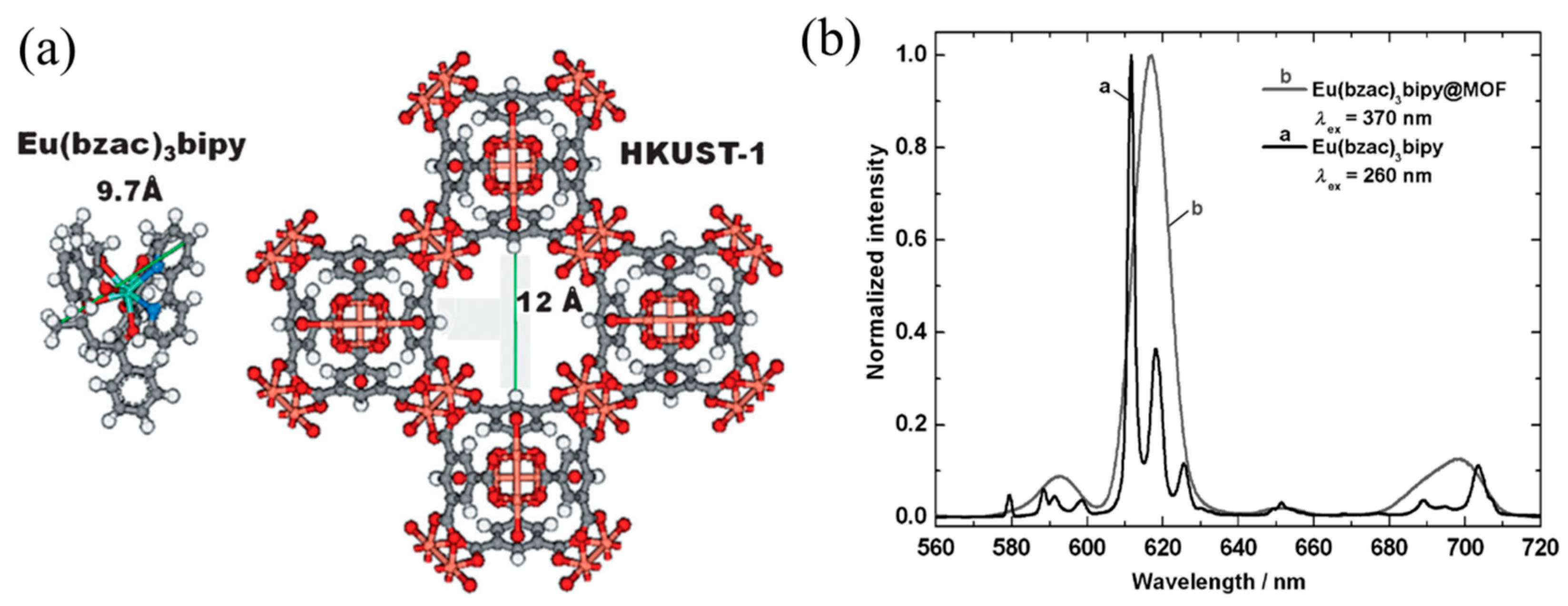
- Streit, H.C.; Adlung, M.; Shekhah, O.; Stammer, X.; Arslan, H.K.; Zybaylo, O.; Ladnorg, T.; Gliemann, H.; Franzreb, M.; Woll, C.; et al. Surface-anchored MOF-based photonic antennae. ChemPhysChem 2012, 13, 2699–2702. [Google Scholar] [CrossRef] [PubMed]
- Cui, Y.; Xu, H.; Yue, Y.; Guo, Z.; Yu, J.; Chen, Z.; Gao, J.; Yang, Y.; Qian, G.; Chen, B. A Luminescent Mixed-Lanthanide Metal–Organic Framework Thermometer. J. Am. Chem. Soc. 2012, 134, 3979–3982. [Google Scholar] [CrossRef] [PubMed]
- Cadiau, A.; Brites, C.D.S.; Costa, P.M.F.J.; Ferreira, R.A.S.; Rocha, J.; Carlos, L.D. Ratiometric Nanothermometer Based on an Emissive Ln3+-Organic Framework. ACS Nano 2013, 7, 7213–7218. [Google Scholar] [CrossRef] [PubMed]
- Xia, T.; Cui, Y.; Yang, Y.; Qian, G. A luminescent ratiometric thermometer based on thermally coupled levels of a Dy-MOF. J. Mater. Chem. C 2017, 5, 5044–5047. [Google Scholar] [CrossRef]
- Shen, X.; Yan, B. Polymer hybrid thin films based on rare earth ion-functionalized MOF: Photoluminescence tuning and sensing as a thermometer. Dalton Trans. 2015, 44, 1875–1881. [Google Scholar] [CrossRef] [PubMed]
- Liu, X.; Fu, W.; Bouwman, E. One-step growth of lanthanoid metal-organic framework (MOF) films under solvothermal conditions for temperature sensing. Chem. Commun. 2016, 52, 6926–6929. [Google Scholar] [CrossRef] [PubMed]
- Carter, K.P.; Young, A.M.; Palmer, A.E. Fluorescent sensors for measuring metal ions in living systems. Chem. Rev. 2014, 114, 4564–4601. [Google Scholar] [CrossRef] [PubMed]
- Xiao, Y.; Cui, Y.; Zheng, Q.; Xiang, S.; Qian, G.; Chen, B. A microporous luminescent metal-organic framework for highly selective and sensitive sensing of Cu2+ in aqueous solution. Chem. Commun. 2010, 46, 5503–5505. [Google Scholar] [CrossRef] [PubMed]
- Wang, X.; Qin, T.; Bao, S.-S.; Zhang, Y.-C.; Shen, X.; Zheng, L.-M.; Zhu, D. Facile synthesis of a water sTable 3D Eu-MOF showing high proton conductivity and its application as a sensitive luminescent sensor for Cu2+ ions. J. Mater. Chem. A 2016, 4, 16484–16489. [Google Scholar] [CrossRef]
- Cho, W.; Lee, H.J.; Choi, G.; Choi, S.; Oh, M. Dual Changes in Conformation and Optical Properties of Fluorophores within a Metal-Organic Framework during Framework Construction and Associated Sensing Event. J. Am. Chem. Soc. 2014, 136, 12201–12204. [Google Scholar] [CrossRef] [PubMed]
- Wang, Y.; Chu, T.; Yu, M.; Liu, H.; Yang, Y. One step cathodically electrodeposited [Tb2(BDC)3(H2O)4]n thin film as a luminescent probe for Cu2+ detection. RSC Adv. 2014, 4, 58178–58183. [Google Scholar] [CrossRef]
- Tan, H.; Liu, B.; Chen, Y. Lanthanide Coordination Polymer Nanoparticles for Sensing of Mercury(II) by Photoinduced Electron Transfer. ACS Nano 2012, 6, 10505–10511. [Google Scholar] [CrossRef] [PubMed]
- Zhu, Y.M.; Zeng, C.H.; Chu, T.S.; Wang, H.M.; Yang, Y.Y.; Tong, Y.X.; Su, C.Y.; Wong, W.T. A novel highly luminescent LnMOF film: A convenient sensor for Hg2+ detecting. J. Mater. Chem. A 2013, 1, 11312–11319. [Google Scholar] [CrossRef]
- Xia, T.; Song, T.; Zhang, G.; Cui, Y.; Yang, Y.; Wang, Z.; Qian, G. A Terbium Metal-Organic Framework for Highly Selective and Sensitive Luminescence Sensing of Hg2+ Ion in Aqueous Solution. Chem. Eur. J. 2016, 22, 18429–18434. [Google Scholar] [CrossRef] [PubMed]
- Yang, J.; Wang, Z.; Li, Y.; Zhuang, Q.; Zhao, W.; Gu, J. Porphyrinic MOFs for reversible fluorescent and colorimetric sensing of mercury(II) ions in aqueous phase. RSC Adv. 2016, 6, 69807–69814. [Google Scholar] [CrossRef]
- Wen, L.; Zheng, X.; Lv, K.; Wang, C.; Xu, X. Two Amino-Decorated Metal–Organic Frameworks for Highly Selective and Quantitatively Sensing of Hg(II) and Cr(VI) in Aqueous Solution. Inorg. Chem. 2015, 54, 7133–7135. [Google Scholar] [CrossRef] [PubMed]
- Zhang, X.; Xia, T.; Jiang, K.; Cui, Y.; Yang, Y.; Qian, G. Highly sensitive and selective detection of mercury(II) based on a zirconium metal-organic framework in aqueous media. J. Solid State Chem. 2017, 253, 277–281. [Google Scholar] [CrossRef]
- Rudd, N.D.; Wang, H.; Fuentes-Fernandez, E.M.; Teat, S.J.; Chen, F.; Hall, G.; Chabal, Y.J.; Li, J. Highly Efficient Luminescent Metal-Organic Framework for the Simultaneous Detection and Removal of Heavy Metals from Water. ACS Appl. Mater. Interfaces 2016, 8, 30294–30303. [Google Scholar] [CrossRef] [PubMed]
- Yee, K.-K.; Reimer, N.; Liu, J.; Cheng, S.-Y.; Yiu, S.-M.; Weber, J.; Stock, N.; Xu, Z. Effective Mercury Sorption by Thiol-Laced Metal–Organic Frameworks: In Strong Acid and the Vapor Phase. J. Am. Chem. Soc. 2013, 135, 7795–7798. [Google Scholar] [CrossRef] [PubMed]
- Feng, J.F.; Yang, X.; Gao, S.Y.; Shi, J.; Cao, R. Facile and Rapid Growth of Nanostructured Ln-BTC Metal-Organic Framework Films by Electrophoretic Deposition for Explosives sensing in Gas and Cr3+ Detection in Solution. Langmuir 2017, 33, 14238–14243. [Google Scholar] [CrossRef] [PubMed]
- Jia, X.X.; Yao, R.X.; Zhang, F.Q.; Zhang, X.M. A Fluorescent Anionic MOF with Zn4(trz)2 Chain for Highly Selective Visual Sensing of Contaminants: Cr(III) Ion and TNP. Inorg. Chem. 2017, 56, 2690–2696. [Google Scholar] [CrossRef] [PubMed]
- Sun, N.-N.; Yan, B. Rapid and facile ratiometric detection of CO32− based on heterobimetallic metal–organic frameworks (Eu/Pt-MOFs). Dyes Pigments 2017, 142, 1–7. [Google Scholar] [CrossRef]
- Lian, X.; Yan, B. A postsynthetically modified MOF hybrid as a ratiometric fluorescent sensor for anion recognition and detection. Dalton Trans. 2016, 45, 18668–18675. [Google Scholar] [CrossRef] [PubMed]
- Dou, Z.; Cai, J.; Cui, Y.; Yu, J.; Xia, T.; Yang, Y.; Qian, G. Preparation and Gas Separation Properties of Metal-Organic Framework Membranes. Z. Anorg. Allg. Chem. 2015, 641, 792–796. [Google Scholar] [CrossRef]
- Xu, R.; Wang, Y.; Duan, X.; Lu, K.; Micheroni, D.; Hu, A.; Lin, W. Nanoscale Metal–Organic Frameworks for Ratiometric Oxygen Sensing in Live Cells. J. Am. Chem. Soc. 2016, 138, 2158–2161. [Google Scholar] [CrossRef] [PubMed] [Green Version]
- Zhang, F.; Wang, Y.; Chu, T.; Wang, Z.; Li, W.; Yang, Y. A facile fabrication of electrodeposited luminescent MOF thin films for selective and recyclable sensing of nitroaromatic explosives. Analyst 2016, 141, 4502–4510. [Google Scholar] [CrossRef] [PubMed]
- Zhao, C.W.; Ma, J.P.; Liu, Q.K.; Wang, X.R.; Liu, Y.; Yang, J.; Yang, J.S.; Dong, Y.B. An in situ self-assembled Cu4I4-MOF-based mixed matrix membrane: A highly sensitive and selective naked-eye sensor for gaseous HCl. Chem. Commun. 2016, 52, 5238–5241. [Google Scholar] [CrossRef] [PubMed]
- Wang, Y.; Zhang, G.; Zhang, F.; Chu, T.; Yang, Y. A novel lanthanide MOF thin film: The highly performance self-calibrating luminescent sensor for detecting formaldehyde as an illegal preservative in aquatic product. Sens. Actuators B-Chem. 2017, 251, 667–673. [Google Scholar] [CrossRef]
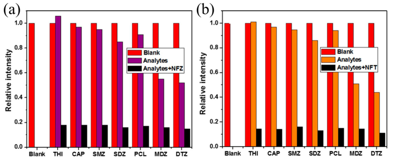
- Zhang, F.; Yao, H.; Chu, T.; Zhang, G.; Wang, Y.; Yang, Y. A Lanthanide MOF Thin-Film Fixed with Co3O4 Nano-Anchors as a Highly Efficient Luminescent Sensor for Nitrofuran Antibiotics. Chem. Eur. J. 2017, 23, 10293–10300. [Google Scholar] [CrossRef] [PubMed]
- Zhang, F.; Yao, H.; Zhao, Y.; Li, X.; Zhang, G.; Yang, Y. Mixed matrix membranes incorporated with Ln-MOF for selective and sensitive detection of nitrofuran antibiotics based on inner filter effect. Talanta 2017, 174, 660–666. [Google Scholar] [CrossRef] [PubMed]


© 2018 by the authors. Licensee MDPI, Basel, Switzerland. This article is an open access article distributed under the terms and conditions of the Creative Commons Attribution (CC BY) license (http://creativecommons.org/licenses/by/4.0/).
Share and Cite
Liao, Z.; Xia, T.; Yu, E.; Cui, Y. Luminescent Metal–Organic Framework Thin Films: From Preparation to Biomedical Sensing Applications. Crystals 2018, 8, 338. https://doi.org/10.3390/cryst8090338
Liao Z, Xia T, Yu E, Cui Y. Luminescent Metal–Organic Framework Thin Films: From Preparation to Biomedical Sensing Applications. Crystals. 2018; 8(9):338. https://doi.org/10.3390/cryst8090338
Chicago/Turabian StyleLiao, Zhengluan, Tifeng Xia, Enyan Yu, and Yuanjing Cui. 2018. "Luminescent Metal–Organic Framework Thin Films: From Preparation to Biomedical Sensing Applications" Crystals 8, no. 9: 338. https://doi.org/10.3390/cryst8090338