Article

Experimental Study on the Oxidation and Diffusion Behavior of Inconel 625 and Tool Materials

1
College of Mechanical and Power Engineering, Harbin University of Science and Technology, Harbin 150080, China
2
Laboratory of Advanced Cutting and Tools Technology, Harbin University of Science and Technology, Harbin 150080, China
*
Author to whom correspondence should be addressed.
Crystals 2018, 8(12), 471; https://doi.org/10.3390/cryst8120471
Submission received: 19 October 2018 / Revised: 12 December 2018 / Accepted: 13 December 2018 / Published: 15 December 2018

Abstract

:
Oxidation and diffusion simulation experiments were conducted to choose the most suitable material for cutting the Inconel 625 superalloy. Three tool materials, WC/Co, coated carbide, and ceramic were used as tool materials in the oxidation simulation experiment. The three tool materials were heated for 30 min in a high-temperature furnace, and the high-temperature oxidation products were examined with scanning electron microscopy and X-ray diffraction (XRD). Tools were heated for 90 min in a vacuum tube furnace. The element diffusion behaviors of Inconel 625 and the tool materials were analysed with energy-dispersive X-ray spectroscopy and XRD. Some of the WC and Co in the WC/Co and coated carbide tool materials was oxidized to WO3, Co3O4, and CoWO4, and the oxidation reaction became more intense as the temperature increased. For the ceramic tool, only TiC was oxidized to TiO2, which indicates good oxidation resistance. In the diffusion couple experiments, the diffusion levels of the three tool materials increased with temperature, but the degree of influence differed. Diffusion of elements was hindered by the (Al, Ti) N coating of the coated carbide and effectively inhibited by the Al2O3 in the ceramic tool. In terms of oxidation and diffusion, the most suitable tool material for cutting Inconel 625 was the ceramic, followed by the coated carbide and then WC/Co.

1. Introduction

Inconel 625 is widely used in engine parts because of its good corrosion resistance and thermal fatigue properties [1]. Several characteristics, including high toughness and ductility, high melting point, excellent resistance to corrosion, thermal shocks, thermal fatigue, and erosion are primarily responsible for its wide domain of application [2]. However, its low thermal conductivity, high strength, and high chemical reactivity limit its machinability [3]. The selection of tool materials for cutting Inconel 625 involves even higher requirements. Tool materials used for cutting Inconel 625 have mainly been WC/Co, coated carbide, ceramics and PCBN (polycrystalline cubic boron nitride). PCBN has been less used because of its high price and because it is easy to produce the phenomenon of tipping when cutting superalloy. Such materials need to allow the tool to have processing accuracy while also improving the processing efficiency and tool life.
Many scholars have researched and theorized on the optimization of tool materials and machining wear [4,5]. Deng et al. analysed the wear mechanism for cutting titanium alloy and stainless steel and optimized the most suitable tool for cutting Ti6Al4V and Cr12Mn5Ni4Mo3Al [6]. Lotfi et al. performed 3D finite element simulations to analyze the wear of coated carbide (Inconel 625) and confirmed that the cutting temperature and cutting force are the two most important factors that limit tool wear [7]. Pan et al. examined the high-speed friction wear characteristics of ultrafine-grained carbide tools and determined the main wear mechanisms to be abrasive and adhesive wear with a small amount of diffusion wear [8]. Zhu et al. studied the tool wear characteristics for cutting the nickel-based superalloy Inconel 718 and proposed that diffusion and oxidation wear were the main wear patterns [9]. Martinez et al. performed an Inconel 718 cutting experiment with TiN- and TiAlN-coated carbide tools. They found that high-speed cutting of a superalloy produces a higher cutting pressure and temperature, while a high cutting temperature was the main factor that induces tool oxidation and diffusion wear [10]. Xavior et al. cut a nickel-based superalloy with carbide tools and found that the main factors that affect tool wear were thermal softening, bonding, diffusion, and groove and thermal cracking of the tool material under high temperature and stress [11]. Comprehensive research has shown that most materials used in low-speed cutting were mainly worn by adhesive wear and oxidation. During the high-speed cutting process, it was difficult for oxygen to enter the contact area of the tool tip. Wear was mainly in the form of diffusion wear under anoxic conditions [12]. However, research on the oxidation and diffusion of tool materials has been limited to phenomena without deep mechanisms, and there have been no systematic studies on the oxidation and diffusion behaviour of Inconel 625 and tool materials.
In this study, Gibbs free energy was used to predict the possible oxidation reactions and products of different tool materials at high temperatures, and oxidation simulation experiments were performed with a diffusion model of each tool material and Inconel 625. Inconel 625 was constructed using Fick’s law, and diffusion couple experiments were conducted. The samples were examined with energy-dispersive X-ray spectroscopy (EDS), X-ray diffraction (XRD), and scanning electron microscopy (SEM) to analyze the oxidation behaviour of the tool materials and their diffusion behaviour with Inconel 625. This research provides evidence for the selection of tool materials for cutting Inconel 625.

2. Experimental Procedures

WC–Co cemented carbide, WC–Co cemented carbide coated with (Al, Ti) N, and Al2O3–TiC ceramic were selected for the tool materials, and Inconel 625 was selected as the workpiece material. It has been observed that the cutting temperature when machining such superalloys can reach a maximum of about 1273 K [13]. Table 1 and Table 2 present the specific components of the tool and workpiece materials, respectively. The information of different materials came from manufacturers: Inconel 625 from Shanghai Chongao Industry Co., Ltd (Shanghai, China); WC/Co from Xiamen Weisina Coating Technology Co., Ltd. (Xiamen, China); coated carbide from Mitsubishi Tools Co. (Shanghai, China); and ceramics from Sandvik Co. (Gimo, Sweden). The tools were cleaned with acetone, blown dry, and weighed on an electronic balance (JA5003, measurement accuracy: 0.0001g). Tool materials were heated for 30 min in a high-temperature heating furnace (pot resistance furnace, SG2-5-10) at 873 K, 973 K, 1073 K, 1173 K, and 1273 K before being cooled to room temperature. The specimens were then taken out and weighed with an electronic balance before the experimental data were recorded. The oxidation products and surface morphology of the specimens were observed with XRD (LabX xrd-6000, Acc.V: 20.00 KV, Current: 100 mA, step size: 0.02 deg, Cu Kα rays, scanning speed: 4 dg/min, SHIMADZU, Kyoto, Japan) and SEM (HITACHI SU3500, Spot: 40, Acc.V: 20.00 KV, Magn: 2000 X, HITACHI, Japan), respectively.
Cylindrical specimens of the tool and workpiece materials with dimensions of φ = 8 mm × 10 mm were used in the diffusion couple experiments. The tool specimens were lapped, polished, and cleaned with acetone. Then, the workpiece and tool specimens were placed in contact with each other to form a diffusion couple, as shown in Figure 1. A clamping force of 10 MPa was maintained on the specimens to ensure a smooth contact surface. The function of pressure was to make the plastic deform near the contact interface to obtain close contact so that elements could diffuse. It has been observed that the cutting temperature when machining such superalloys can reach a maximum of about 1273 K. Hence, the clamped specimens were placed in a vacuum tube furnace and heated for 90 min at 873 K, 973 K, 1073 K, 1173 K, and 1273 K. EDS and XRD were used to detect the element contents and compounds of the specimens, respectively, and the element diffusion coefficients of the tool and workpiece materials were calculated.

3. Results and Discussion

3.1. Oxidation Behaviour of the Tool Material

3.1.1. Theoretical Analysis of the Oxidation Reaction

Table 3 presents the chemical reaction of the tool matrix with oxygen at high temperatures during the superalloy cutting process. Some of the oxidation products were not stable at high temperatures. In Table 4, chemical reactions are presented that easily occurred with other substances.
According to the second law of thermodynamics, if any chemical reaction can proceed spontaneously, the free energy in this reaction process must be reduced. The specific basis for judging a spontaneous response is as follows: if Δ G < 0 , then the reaction proceeds spontaneously; if Δ G = 0 , then the reaction reaches equilibrium; and if Δ G > 0 , then the reaction does not occur.
The Gibbs free energies of the tool and workpiece reactions were calculated as follows:
Δ G T 0 = Δ H 298 0 T Δ T
where Δ G T 0 is the Gibbs free energy in the reaction, Δ H 298 0 is the reaction heat effect, T is the absolute temperature, and Δ T . is the Gibbs free energy function. In Equation (1), Δ T and Δ H 298 0 change with the temperature T. The Gibbs free energy and reaction heat effect of the tool materials according to a relevant handbook [14] were used to obtain the Gibbs free energy at the relevant temperature. Table 3 and Table 4 present the Gibbs free energy of the tool body at 1200 K. Comparison with the Gibbs free energies of the tool materials showed that TiC can more easily oxidize to TiO2 than to TiO and that Co can more easily oxidise to Co3O4 than to CoO. Furthermore, a new chemical reaction occurred between the intermediate products CoWO4 and CO2. The above analysis can be used to predict the chemical reaction with relevant compounds. As WO3 has both gas and solid forms, the gaseous WO3 escapes to the air. In this study, the Gibbs free energy values of the solid WO3 and intermediate products were calculated.

3.1.2. Analysis Results for the Oxidation Reaction Experiment

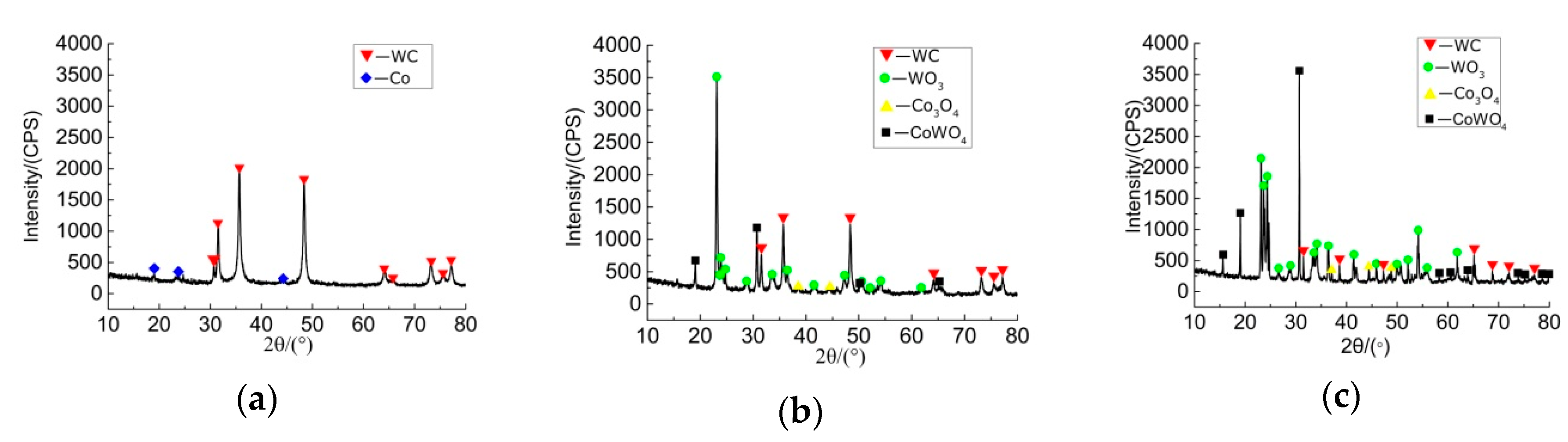
Figure 2a–c shows the XRD patterns of the WC/Co tool at 873 K, 973 K, and 1273 K, respectively. When the temperature was 873 K, there were no obvious oxidation products. When the temperature rose to 973 K, WO3 and Co3O4 were observed, and CoWO4 was produced by the combined reaction between WC and Co. However, when the temperature rose to 1273 K, WC still showed a diffraction peak among the oxidation products, indicating that it was not completely oxidized.
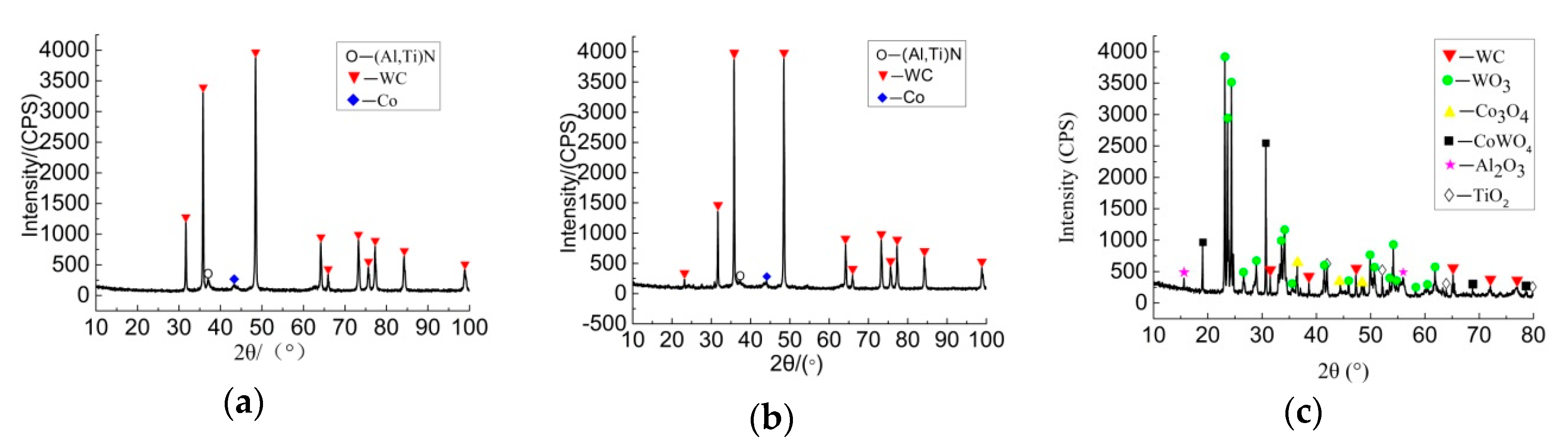
Figure 3a–c shows the XRD pattern charts for the coated carbide tool material at temperatures of 973 K, 1073 K, and 1273 K, respectively. Owing to the coating’s blocking effect, the coated carbide tool showed no obvious oxidation products when the temperature was between 873 K and 1073 K. When the temperature rose to 1273 K, however, not only oxidation products of the tool (i.e., WO3, Co3O4, and CoWO4) but also oxidation products of the coating (i.e., Al2O3 and TiO2) were detected. This was mainly because the oxidation reaction between the coating and matrix composition of the tool occurs at high temperatures.
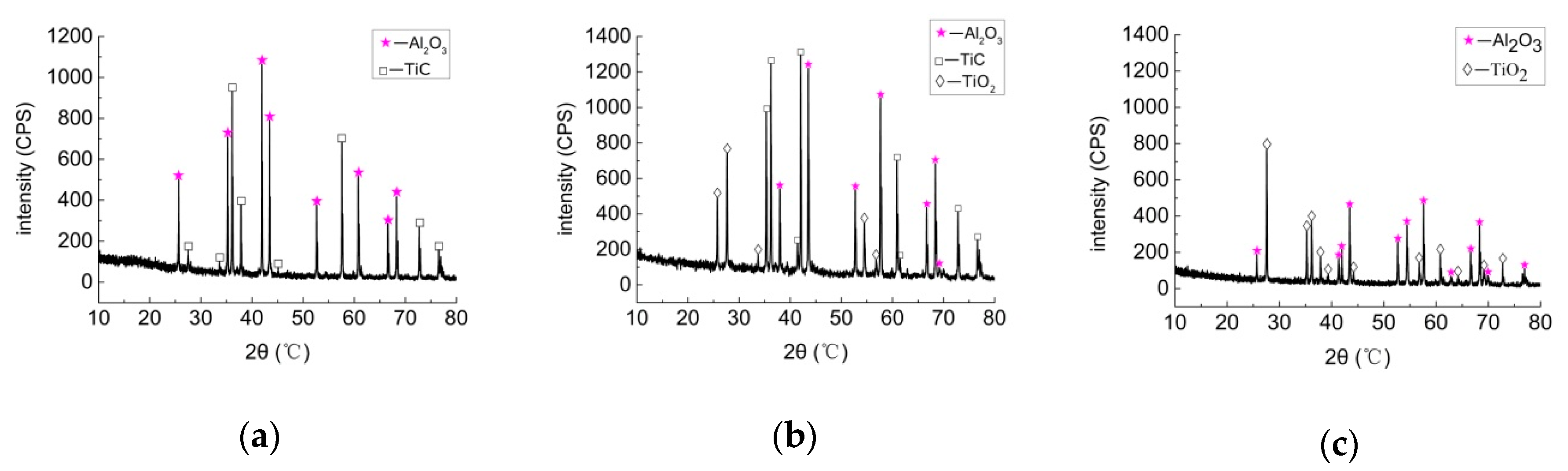
Figure 4a–c shows XRD diagrams of the ceramic material at temperatures of 973, 1173 K, and 1273 K, respectively. When the temperature was 973 K, the tool showed no obvious oxidation products. When the temperature rose to 1173 K, the TiC of the tool produced the oxidation product TiO2, but TiC was still present. When the temperature rose to 1273 K, only TiO2 was observed, with no TiC. Thus, the TiC in the ceramic tool was completely oxidized to TiO2, which is also why the color of the ceramic material changed from cinereous to white. The matrix Al2O3 of the ceramic tool did not change. Therefore, the ceramic tool showed strong antioxidant properties.
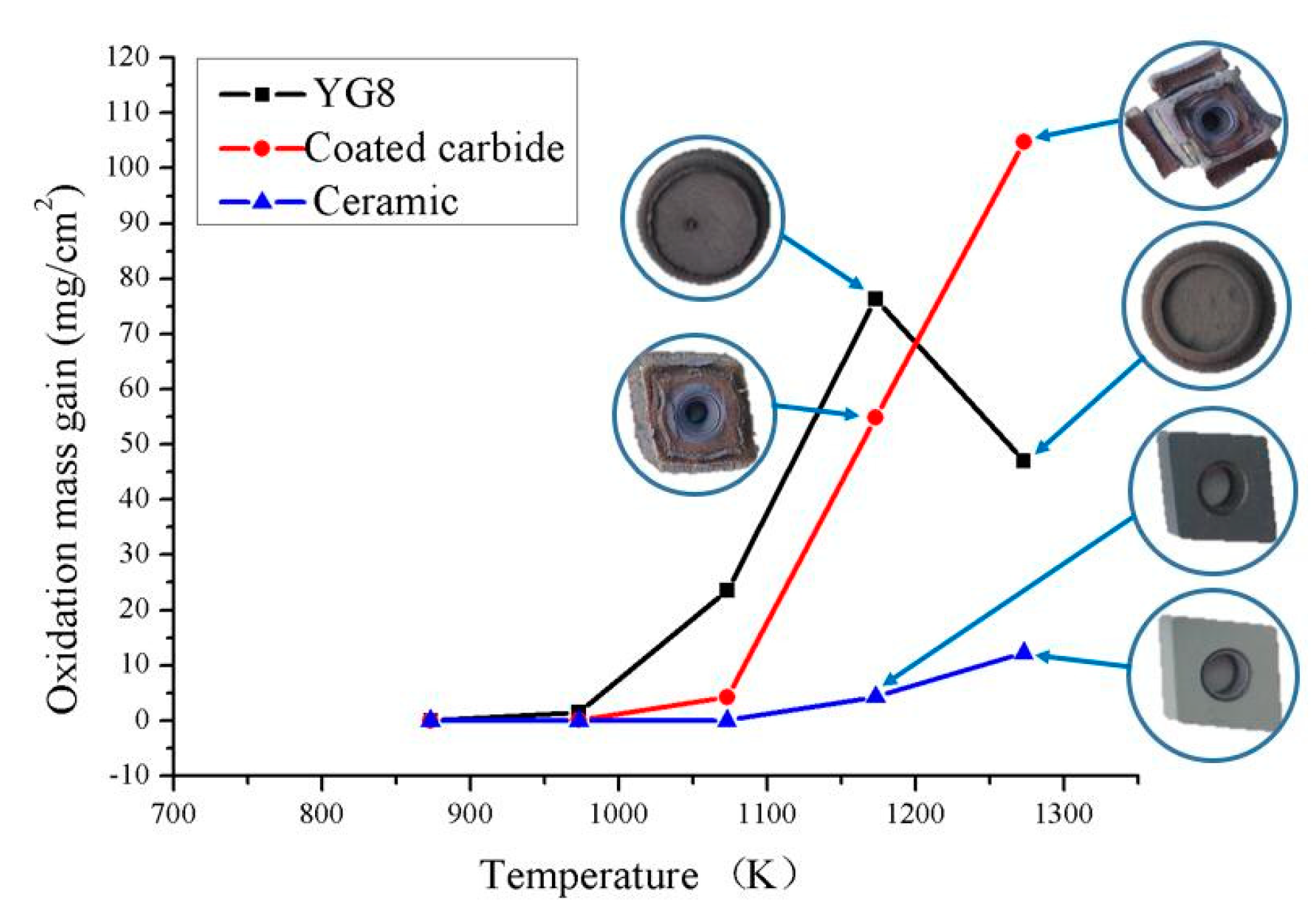
Figure 5 shows the oxidation mass gain curves of different tool materials at different temperatures. When the temperature was lower than 1000 K, there was no obvious mass gain due to tool material oxidation. Around 1000 K, the oxidation mass gain phenomenon appeared. As the temperature rose, the mass increased sharply owing to oxidation. The peak mass gain occurred when the temperature rose to about 1200 K. This was mainly because of WO3 sublimation at the tool surface at 1100 K. This generated extensive contact between the tool matrix and oxygen in the air, which sharply increased the oxidation of the tool material. As the temperatures rose, the oxidation mass gain began to decrease. This was mainly because high temperatures caused an oxide film to form, which separated the cutting tool material from oxygen. This made the oxidation reaction difficult. As the temperature increased, the sublimation of WO3 and CO2 gas escape caused the oxidation mass gain to decrease.
The oxidation mass gain of the coated carbide tool occurred at 1100 K with a sharp increase; the trend was similar to that of WC/Co. When the temperature rose to 1200 K, the oxidation mass gain continued to increase and eventually exceeded that of WC/Co. This was because Al on the coating surface was oxidized to Al2O3, which attached to the tool surface and formed an oxide layer with a good protective effect on the tool matrix. The oxygen entered the tool matrix through the pores and defects of the coating as the temperature increased from 1100 K to 1200 K. This led to matrix oxidation and edge cracking of the oxide layer, which intensified the oxidation reaction. Owing to the extensive contact between the tool matrix material and oxygen, there was a significant increase in the oxidation mass gain. This was also the reason for the large area shedding at the high temperature of 1273 K.
The ceramic tool did not show an obvious oxidation mass gain below 1100 K, but the mass began to slowly increase at 1100 K and above. As the tool matrix was Al2O3 in the experiment, the ceramic tool showed good oxidation resistance. However, the oxidation mass gain increased slowly because TiC in the ceramic tool was oxidized to TiO2 at high temperatures.
As shown in Figure 5, the oxidation mass gain of WC/Co was not obvious until the temperature reached 973 K. 
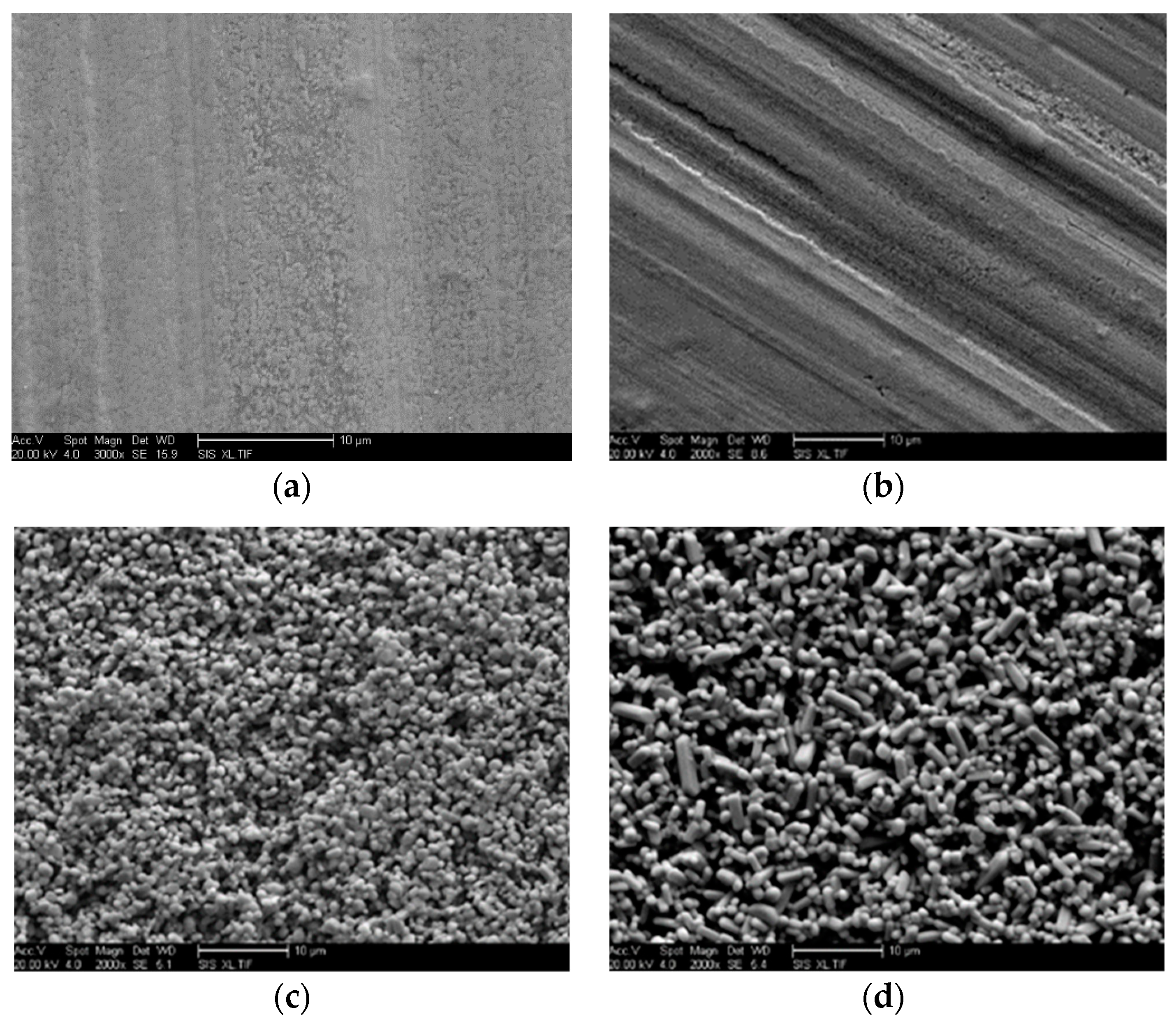
Figure 6a–d shows SEM images of the WC/Co tool material at temperatures of room temperature, 873 K, 1173 K, and 1273 K, respectively. A compact oxidation layer appeared on the tool surface and totally covered it at 1173 K. When the temperature rose to 1273 K, the oxide particles in the oxide layer increased in size, and obvious gaps appeared between the particles. There were two reasons for this. First, some oxides were in a gaseous state at high temperatures. For example, the oxidation product of WC (WO3) had two forms: solid and gas. At 1100 K, the formation of solid WO3 was the main reaction. When the temperature rose to 1200 K, gaseous WO3 formed easily, and the main form of WO3 was gaseous. As the gaseous WO3 escaped, gaps appeared on the surface of the compact oxidation film. Second, the solid WO3 sublimated at high temperatures, which resulted in gaps appearing in the compact oxide film. Oxygen then penetrated the cutter through the gap and continued to react with the tool material, which reduced the tool performance. In addition, products such as WO3 and Co3O4 reacted with oxygen and produced CoWO4 with CO2, and CO2 escaped to also produce gaps. In general, the sublimation of WO3 and generation of gaseous WO3 and CO2 reduced the oxidation mass gain of the tool material, which coincided with the oxidation mass gain curve shown in Figure 5.
According to 
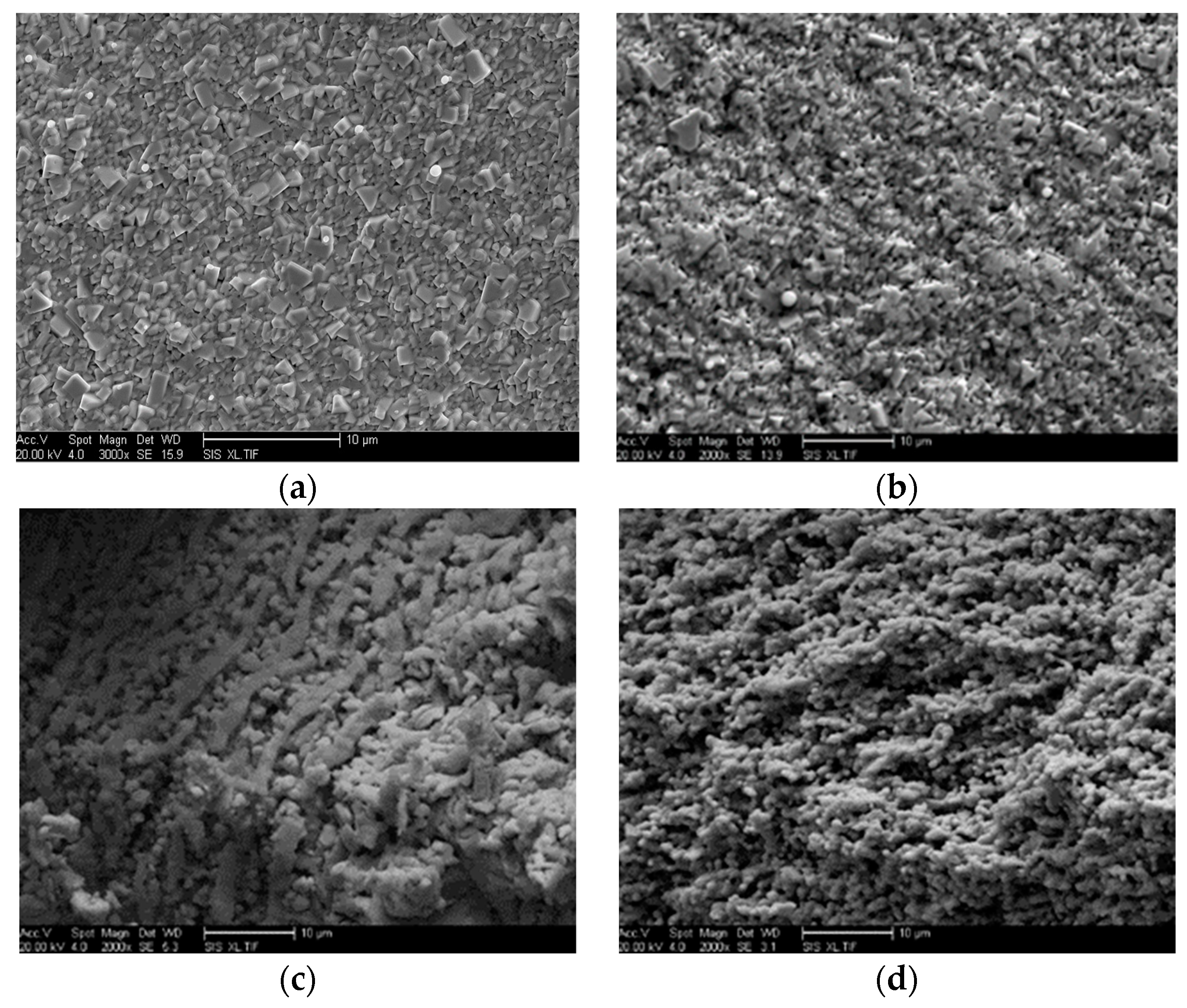
Figure 5, the oxidation mass gain of the coated carbide tool was not obvious before the temperature rose to 1100 K, and there was no significant oxidation of the tool material. The tool material showed obvious oxidation when the temperature rose to 1173 K. Figure 7a–d shows SEM images of the carbide tools at temperatures of room temperature, 973 K, 1173 K, and 1273 K, respectively. At 1173 K, the coating was not completely shed, with some remaining on the oxide surface of the tool material. Loss of the coating aggravated the oxidation of the tool material. When the temperature rose to 1273 K, the coating of the tool material had completely fallen off, and the matrix of the tool material was fully oxidized. Gaps also appeared between the oxide granules for reasons similar to those described for the WC/Co tool material.
As shown in 
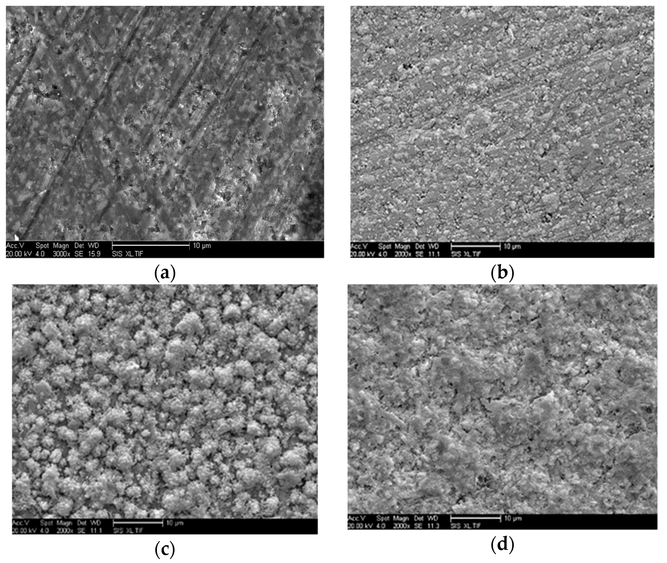
Figure 5, the mass gain of the ceramic tool was not obvious at 973 K. The oxidation mass gain of the tool material increased slowly when the temperature rose to 1173 K. Figure 8a–d shows SEM images of the ceramic tool material at temperatures of room temperature, 973, 1173 K, and 1273 K, respectively. Figure 4 shows that the oxidation product TiO2 was observed at 1173 K, but part of the TiC was not oxidized. The TiC in the tool material completely oxidized to TiO2 when the temperature was increased to 1273 K. As shown in Figure 8, a large amount of oxidation product was found on the surface of the tool material at 973 K. Larger oxide particles appeared on the surface of the tool material at 1173 K. At 1273 K, the tool oxidation products continued to increase, and the surface was covered with oxidized particles.
The above analysis indicates that the different kinds of tool materials showed different degrees of oxidation at high temperatures. The ceramic tool material had the lowest degree of oxidation. The WC/Co tool material showed slight oxidation at 973 K and very intense oxidation at 1173 K. The coated carbide tool material showed an obvious oxide layer at 1173 K, and the coating started to chip. At 1273 K, the coating of the cutter was chipped over a large area. In conclusion, the ceramic tool material showed the strongest antioxidant properties, followed by the coated carbide and then WC/Co. Severe oxidation of tool materials will result in a rapid deterioration in material properties [15].

3.2. Diffusion Behaviour of the Tool Material

3.2.1. Elemental Diffusion Mechanism

According to Fink’s laws of diffusion, elements from two tightly attached objects diffuse to some degree from the object with the higher concentration to the one with the lower concentration. During the experimental process, which was limited to 90 min, the concentration at each point changed with the diffusion distance. This was used to set diffusion models according to Fink’s second law of diffusion:
C ( x , t ) = C 1 2 ( 1 e r f x 2 D t )
where C represents the concentration of the diffusion element (kg/m3), C1 represents the initial concentration of the diffusion element (kg/m3), t represents the diffusion time (s), x represents the diffusion distance (m), and D is the diffusion coefficient (m2/s). Equation (2) gives the relationship between the concentration and distance of diffusion elements so that the diffusion concentration can be obtained at different distances.

3.2.2. Analysis of the Diffusion Experiment

To verify that the experimental results were satisfactory, an analysis was performed on the line scans of the tool and workpiece materials shown in Figure 9, and the XRD patterns of the tool material shown in Figure 10. As shown in Figure 9a–c, the elements in the three tool materials had different degrees of diffusion at 873 K. Diffusive reactions also occurred at lower temperatures. As shown in Figure 10, the material composition of the tool showed almost no change at 1273 K. The oxidation simulation experiments showed that more significant oxidation reaction phenomena occurred at higher temperatures and that the three tool materials diffused at various temperatures. No oxidation reaction occurred during the experiment, and the experiment reached the expected state.
In order to quantify the element diffusion behaviour, EDS was used to analyze the diffusion element concentration at points on both sides of the contact interface. The diffusion element concentrations were then used to draw diffusion curves. Figure 11 shows the element diffusion curves of Inconel 625 and the three tool materials at temperatures of 873 K, 1173 K, and 1273 K. Figure 11 was scanned by Figure 9. As shown in Figure 11a, b and g, the intensity of the diffusion of the main element W of WC/Co into Inconel 625 significantly increased with increasing temperature, as did the intensity of diffusion of the main elements Ni and Cr from Inconel 625 to WC/Co. As shown in Figure 11b, e, and h, the diffusion of the main elements Al and Ni of the coated carbide tool to Inconel 625 became significant as the temperature increased, while the elements Ti and Cr showed less variation in the degree of diffusion. As shown in Figure 11c, f and i, the diffusion of elements between the ceramic tool and Inconel 625 was very weak at the different temperatures. Comparisons showed that the elemental diffusion of the different materials varied drastically at different temperatures. The temperature had the greatest effect on the diffusion intensity of WC/Co, followed by that of the coated carbide and then that of the ceramic.
According to the diffusion distances of Inconel 625 with the three tool materials, the ceramic tool showed excellent diffusion inhibition. For example, Figure 11i shows the diffusion of the elements Al and Ti of the ceramic tool into Inconel 625 at 1273 K. The diffusion distance was about 5 µm. Ni diffused from Inconel 625 to the ceramic tool, and the diffusion distance was about 10 µm. Al and Ti in the coated carbide tool diffused into Inconel 625, and the diffusion distance was about 10 µm. Ni diffused from Inconel 625 into the coated carbide tool, and the diffusion distance was about 15 µm. The diffusion distances of Ni and W between WC/Co and Inconel 625 both reached 20 µm.
The collected data shown in Figure 11 were used to obtain the initial concentrations of the elements and the concentrations of each diffusion element. The diffusion coefficients were calculated using the diffusion model. Table 5, Table 6 and Table 7 present the diffusion coefficients of the main elements in the three tool materials and Inconel 625. Compared with the other two tools, the diffusion coefficient of the WC/Co tool was most affected by the temperature. Table 5 indicates that the diffusion coefficients of the main elements of WC/Co and Inconel 625 increased significantly with increasing temperature. For example, the diffusion coefficient for Cr increased from 4.04 × 10⁻¹⁵ m2/s to 1.32 × 10⁻¹⁴ m2/s between 873 K and 1273 K. The diffusion coefficients of each element also differed at the same temperature. For example, at 1273 K, W had a smaller diffusion coefficient than any of Cr, Co, and Ni, so it had a smaller diffusion capacity. In Table 6 and Table 7, the diffusion coefficients of the coated carbide and ceramic tools changed less as the temperature increased. In the case of the coated carbide tool, the surface coating prevented the diffusion of elements, resulting in lower diffusion coefficients than those of the WC/Co tool at the same temperature. The diffusion coefficient of Cr in the coated carbide tool was most affected by the temperature. Between 873 K and 1273 K, the diffusion coefficient increased from 9.85 × 10⁻¹⁶ m2/s to 1.63 × 10⁻¹⁵ m2/s. The diffusion coefficients of the ceramic tool increased slowly with increasing temperature. In addition, each element of the ceramic tool had a small diffusion coefficient. Cr had a larger diffusion coefficient than the other three elements, but it was still only 1.46× 10⁻¹⁵ m2/s at 1273 K.
W and Ni are the main components of WC/Co and Inconel 625, respectively, and changes in their concentrations affected the mechanical properties of the tool and the alloy. At the same time, W and Ni were the two elements that showed the highest degree of diffusion. When element diffusion occurred in WC/Co and Inconel 625, W had a significantly higher initial concentration than the other three elements (Cr, Co, and Ni), so the diffusion concentration of W was greater than those of the others at each temperature. When the temperature was increased from 873 K to 1173 K, the Ni atoms moved rapidly, and the diffusion concentration value gradually increased. When the temperature was increased to 1273 K, the activity intensities of the W and Ni atoms increased even further, and the original concentrations of W and Ni were relatively high. Therefore, the W and Ni elemental diffusion concentrations clearly increased. Owing to the low initial concentrations of Co and Cr, their diffusion concentrations were not obvious, but their diffusion coefficients were similar to those of the other two elements. The coated carbide tool and Inconel 625 had similar element diffusion tendencies to that of WC/Co, but the intensity of the element diffusion was not significant. This is because the coating provided good protection and obstruction, which prevented the tool and workpiece elements from diffusing. As the temperature increased, the coating spalled, which reduced its resistance to element diffusion. Thus, the degree of diffusion of Al and Ni began to increase. Although Ti and Cr had relatively small concentrations, the increase in element diffusion was not obviously connected with temperature. However, the diffusion coefficients indicated that the two elements had greater diffusion than the other elements. The ceramic tool and Inconel 625 had the weakest degree of diffusion. This was because the Al2O3 barrier layer formed a defect-free hcp crystal structure. In such a structure, the atomic arrangement is tight and orderly, and there is no phase change when the temperature is increased to its melting point. It also has excellent bonding strength and can effectively inhibit element diffusion [16]. In summary, the elemental diffusion intensity of Inconel 625 and the three tool materials were quite different. The elemental diffusion intensity was highest with WC/Co, followed by the coated carbide and then the ceramic. Element diffusion between a cutting tool and the workpiece material leads to composition change of the tool, which may increase the possibility of mechanical damage to the tool [17]. In terms of diffusion, the ceramic material is preferable for cutting Inconel 625.

4. Conclusions

Oxidation and diffusion experiments were carried out on Inconel 625 with three tool materials (WC/Co, coated carbide and ceramic). The results led to the following conclusions:
(1) For WC/Co the oxidation reaction occurred at 973 K, with WC and Co being oxidized to WO3 and Co3O4 as well as the common product CoWO4. As the temperature was increased, the oxidation behaviour became more intense. WO3 sublimated, so the oxidation mass gain increased before decreasing. The coated carbide tool showed obvious oxidation behaviour at 1173 K, and it started to shed its coating. When the temperature rose to 1273 K, a large area of the tool material showed shedding. The ceramic tool material showed good oxidation resistance with almost no oxidation mass gain. TiC was oxidized only to TiO2.
(2) The diffusion capacities of the three tool materials and the superalloy Inconel 625 increased with temperature. The main elements affected were W and Ni. The diffusion coefficient of W was very large, and the diffusion capacity of Ni increased with temperature. Because of the hindering effect of the coating on element diffusion and the closed structure of the ceramic tool material (Al2O3), neither these two tool materials nor Inconel 625 showed any obvious diffusion. The experimental results showed that the ceramic tool material had the highest capacity for diffusion resistance.
(3) In terms of oxidation and diffusion, the ceramic material is preferable for cutting Inconel 625, followed by the coated carbide and then YG8.

Author Contributions

Conceptualization, E.L. and N.W.; methodology, Z.X. and X.L.; data curation, H.Z. and J.Q.; writing—original draft preparation, E.L. and N.W.; writing—review and editing, N.W.

Funding

This research was funded by the National Natural Science Foundation of China (Granted Number: 51475126), the Youth Science and Technology Innovation Talents Foundation of Harbin (Granted Number: 2016RAQXJ001).

Acknowledgments

This work was supported by the National Natural Science Foundation of China (Granted Number: 51575145).

Conflicts of Interest

The authors declare no conflict of interest.

References

  1. Pervaiz, P.; Rashid, A.; Deiab, I.; Nicolescu, M. Influence of tool materials on machinability of titanium- and nickel-based alloys: A review. Mater. Manuf. Process. 2014, 29, 219–252. [Google Scholar] [CrossRef]
  2. Thakur, A.; Gangopadhyay, S. State-of-the-art in surface integrity in machining of nickel-based superalloys. Int. J. Mach. Tools Manuf. 2016, 100, 25–54. [Google Scholar] [CrossRef]
  3. Wang, C.D.; Wang, C.Y.; Chen, M. Microstructures and machinability of the Inconel 182 overlays at different overlay thickness deposited by shield metal arc welding. Proc. Inst. Mech. Eng. Part B 2015, 231, 1713–1724. [Google Scholar] [CrossRef]
  4. Deng, J.; Li, Y.; Song, W. Diffusion wear in dry cutting of Ti–6Al–4V with WC/Co carbide tools. Wear 2008, 265, 1776–1783. [Google Scholar]
  5. Lotfi, M.; Jahanbakhsh, M.; Farid, A.A. Wear estimation of ceramic and coated carbide tools in turning of Inconel 625: 3D FE analysis. Tribol. Int. 2016, 99, 107–116. [Google Scholar] [CrossRef]
  6. Deng, J.; Zhou, J.; Zhang, H.; Yan, P. Wear mechanisms of cemented carbide tools in dry cutting of precipitation hardening semi-austenitic stainless steels. Wear 2011, 270, 520–527. [Google Scholar]
  7. Pan, Y.; Ai, X.; Zhao, J. Study on high-speed friction and wear behavior of ultrafine grained cemented carbide. Tribology 2008, 28, 179–188. [Google Scholar]
  8. Zhu, D.; Zhang, X.; Ding, H. Tool wear characteristics in machining of nickel-based superalloys. Int. J. Mach. Tools Manuf. 2013, 64, 60–77. [Google Scholar] [CrossRef]
  9. Martinez, I.; Tanaka, R.; Yamane, Y.; Sekiya, K.; Yamada, K.; Yamada, S.; Hasegawa, M. Effect of coating layer loss on the wear rate change of coated carbide tools in turning process. Adv. Manuf. Process. 2017, 50, 1–7. [Google Scholar] [CrossRef]
  10. Xavior, M.A.; Manohar, M.; Jeyapandiarajan, P.; Madhukar, P.M. Tool wear assessment during machining of Inconel 718. Procedia Eng. 2017, 174, 1000–1008. [Google Scholar] [CrossRef]
  11. Bhatt, A.; Attia, H.; Vargas, R.; Thomson, V. Wear mechanisms of WC coated and uncoated tools in finish turning of Inconel 718. Tribol. Int. 2010, 43, 1113–1121. [Google Scholar] [CrossRef]
  12. Long, Z.H.; Wang, X.B.; Liu, Z.B. Research on wear modes and mechanism of carbide tools in high-speed milling of difficult-to-cut materials. Tribol. Int. 2005, 25, 83–87. [Google Scholar]
  13. Chuan, Z.H. The Characteristics of the Cutting Force and Temperature When Machining Nickel-base Alloys. Tool Eng. 1995, 28, 35–37. [Google Scholar]
  14. Wang, J.; Jia, J.; Jia, Y. The Structure Analysis and Antigenicity Study of the N Protein of SARS-CoV. Genomics, Proteomics & Bioinformatics. Genom. Proteom. Bioinform. 2003, 1, 145–154. [Google Scholar]
  15. Shi, A.H.; Su, Q.; Liu, B.X.; Chen, G.J.; Yang, B. High efficiency oxidation behaviour of waste cemented carbide. Chin. J. Rare Met. 2016, 40, 1138–1144. [Google Scholar]
  16. Li, Y.; Xie, Y.; Huang, L.; Liu, X.; Zheng, X. Effect of physical vapor deposited Al2O3 film on TGO growth in YSZ/CoNiCrAlY coatings. Ceram. Int. 2012, 38, 5113–5121. [Google Scholar] [CrossRef]
  17. Li, M.H.; Sun, X.F.; Zhang, Z.Y.; Hu, W.Y.; Hou, G.C.; Guan, H.R.; Hu, Z.Q. Element diffusion and interface characteristics between NiCrAlY coating and Ni-base single crystal superalloy. Rare Met. Mater. Eng. 2004, 33, 55–58. [Google Scholar]
Figure 1. Clamping of the tool material and Inconel 625 specimen.
Crystals 08 00471 g001
Figure 2. X-ray diffraction (XRD) patterns of WC/Co at different temperatures: (a) 873 K, WC: PDF#65-4539; Co: PDF#65-9722; (b) 973 K, WO3: PDF#71-0305; CoWO4: PDF#72-0479; Co3O4: PDF#42-1467; WC: PDF#65-4539; and (c) 1273 K, Co3O4: PDF#42-1467; CoWO4: PDF#72-0479; WO3: PDF#71-0305; WC: PDF#65-4539.
Crystals 08 00471 g002
Figure 3. XRD patterns of the coated carbide tool at different temperatures: (a) 873 K, WC: PDF#65-4539; Co: PDF#15-0806; (Al, Ti)N: PDF #16-0867; (b) 973 K, WC: PDF#65-4539; Co: PDF#15-0806; (Al, Ti)N: PDF #16-0867; (c) 1273K, WO3: PDF#71-0131; CoWO4: PDF#72-0479; WC: PDF#25-1047; TiO2: PDF#23-1446; Al2O3: PDF#16-0394; Co3O4: PDF#42-1467).
Crystals 08 00471 g003
Figure 4. XRD patterns of the ceramic tool oxidation products at different temperatures. (a) 973 K, Al2O3: PDF#70-3319; TiC: PDF#65-8803; (b) 1173 K, Al2O3: PDF#70-3319; TiC: PDF#65-8803; TiO2: PDF#21-1236; (c) 1273 K, Al2O3: PDF#16-0394; TiO2: PDF#21-1236.
Crystals 08 00471 g004
Figure 5. Oxidation mass gain curves of different tool materials versus temperature. (The insets indicate the changes in physical form and colour of the tool materials).
Crystals 08 00471 g005
Figure 6. Oxidation morphology of WC/Co at different temperatures: (a) room temperature (b) 873 K, (c) 1173 K, and (d) 1273 K.
Crystals 08 00471 g006
Figure 7. Oxidation morphology of the coated carbide tool at different temperatures: (a) room temperature (b) 873 K, (c) 1173 K, and (d) 1273 K.
Crystals 08 00471 g007
Figure 8. Oxidation morphology of the ceramic tool at different temperatures: (a) room temperature (b) 873 K, (c) 1173 K, and (d) 1273 K.
Crystals 08 00471 g008
Figure 9. Line scan of the tool materials and Inconel 625 at 873 K. (a) WC/Co, (b) coated carbide, and (c) ceramic.
Crystals 08 00471 g009
Figure 10. XRD patterns of the tool material at 1273 K. (a) WC/Co, (b) coated carbide, and (c) ceramic.
Crystals 08 00471 g010
Figure 11. Element diffusion curves between tool material and Inconel 625. (a) WC/Co (973 K), (b) coated carbide (973 K), (c) ceramic (973 K), (d) WC/Co (1173 K), (e) coated carbide (1173 K), (f) ceramic (1173 K), (g) WC/Co (1273 K), (h) coated carbide (1273 K), and (i) ceramic (1273 K). (Error bars are smaller than the symbols.)
Crystals 08 00471 g011
Table 1. Percentage composition of the three tool materials.
Tool MaterialChemical Composition (wt%)
WC/CoWCCo
928
Coated Carbide (CNGG120408)CAlWTiN
8.1910.9131.3142.86.79
Ceramic (CNGA120408)CAlOTi
12.0839.6231.5716.73
Table 2. Element composition of Inconel 625.
Element Content%NiCrMoNbFeAlTiCMnSiCuPS
Min582083.15---------
Max-23104.1550.40.40.10.50.50.50.0150.015
Table 3. Possible oxidation reactions on the tool.
Tool ComponentsPossible Oxidation ReactionsGibbs Free Energy (kJ)
WC, Co, TiC2WC + 5O2 = 2WO3 + 2CO2−2100.4
2TiC + 3O2 = 2TiO + 2CO2−1482.9
TiC + 2O2 = TiO2 + 2CO2−1757.5
WC + 2O2 = WO2 + CO2−855.7
3Co + 2O2 = Co3O4−525.8
2Co + O2 = 2CoO−361.2
Table 4. Possible reactions with the oxidation products.
Oxidation ProductsPossible ReactionsGibbs Free Energy (kJ)
Co3O4, WO3, CoOCo3O4 + 0.5C + 3WO3 = 3CoWO4 + 0.5CO2−3073.2
Co3O4 + C + 3WO3 = 3CoWO4 + CO−2852.2
CoO + WO3 = CoWO4−853.6
Table 5. Diffusion coefficients of the main elements of WC/Co and Inconel 625 (90 min).
Diffusion TemperatureDiffusion Coefficient (m2/s)
WCrCoNi
873 K(4.35 ± 0.42) × 10−15(4.04 ± 0.35) × 10−15(4.96 ± 0.49) × 10−15(2.12 ± 0.79) × 10−15
1173 K(6.02 ± 0.69) × 10−15(9.13 ± 0.76) × 10−15(1.36 ± 0.31) × 10−14(6.79 ± 0.35) × 10−15
1273 K(9.91 ± 1.11) × 10−15(1.32 ± 0.53) × 10−14(1.79 ± 0.59) × 10−14(1.78 ± 0.30) × 10−14
Table 6. Diffusion coefficients of the main elements of the coated carbide and Inconel 625 (90 min).
Diffusion TemperatureDiffusion Coefficient (m2/s)
CrAlNiTi
873 K(9.85 ± 0.79) × 10−16(1.52 ± 0.26) × 10−15(1.28 ± 0.11) × 10−15(1.23 ± 0.12) × 10−15
1173 K(7.85 ± 1.21) × 10−16(1.85 ± 0.02) × 10−15(1.70 ± 0.18) × 10−15(1.13 ± 0.15) × 10−15
1273 K(1.63 ± 0.06) × 10−15(2.34 ± 0.25) × 10−15(1.78 ± 0.21) × 10−15(2.40 ± 0.31) × 10−15
Table 7. Diffusion coefficients of the main elements of the ceramic tools and Inconel 625 (90 min).
Diffusion TemperatureDiffusion Coefficient (m2/s)
AlTiNiCr
873 K(7.91 ± 1.25) × 10−16(9.9 ± 2.10) × 10−16(9.87 ± 1.19) × 10−16(1.35 ± 0.12) × 10−15
1173 K(8.08 ± 1.23) × 10−16(1.26 ± 0.02) × 10−15(9.58 ± 1.45) × 10−16(1.35 ± 0.12) × 10−15
1273 K(1.02 ± 0.05) × 10−15(1.56 ± 0.04) × 10−15(9.94 ± 2.12) × 10−15(1.46 ± 0.25) × 10−15

