1. Introduction
Quasicrystals, whose early study was inspired by decision theory [
1,
2] and simple mathematical curiostiy [
3], later became a major area of research in material science [
4,
5,
6,
7,
8,
9] and have found applications in areas as wide-ranging as high-energy physics [
10,
11], conformal field theory [
12] quantum computing [
13,
14,
15], and biology [
16,
17,
18]. Two of the most common methods for mathematically constructing quasicrystals, the dual multigrid (or generalized dual) method and the cut-and-project (or direct project, or model set) construction, provide theoretical foundations and many tools for their study [
6,
19]. They help elucidate links between symmetries in different numbers of dimensions and, of particular interest in the present work, the connections between crystallographic and non-crystallographic symmetries.
The Fibonacci multigrid method is a variation of the common dual multigrid method, wherein the spacing of the grid planes is a Fibonacci chain rather than periodic, and the quasicrystal vertices are intersection points of these planes as they occur directly in the grid space, rather than being dual-space vertices (which correspond to tiles in the grid space) [
6,
20]. For non-crystallographic point symmetries such as
(pentagonal) and
(icosahedral), the regular grids have intersection points that are arbitrarily close to each other, but the Fibonacci spacing resolves this to provide finite minimal spacing, and therefore a discrete Fourier spectrum. In Part I of this series, Fang and Irwin have studied an
version [
21,
22], referred to as the Fibonacci icosagrid (FIG), and have shown that it is closely related to sections of the Elser–Sloane quasicrystal (ESQC), a 4D quasicrystal derived by direct cut-and-project from the
root lattice [
23].
The fact that this
quasicrystal was related to the ESQC was not entirely surprising, since the ESQC has
symmetry and is known to contain
symmetric cross-sections [
24]. Somewhat more surprising, perhaps, was the fact that the relationship with the FIG was not based on such a cross-section, but on a tetrahedrally symmetric cross-section which was then compounded 5-fold in 3D. This is related to the fact that the icosagrid itself can be seen as a 5-fold compound of tetragrids, just as the vertices of a dodecahedron (icosahedrally symmetric) are given by a compound of five tetrahedra (
Figure 1). (Throughout this paper, we shall often identify a polytope or compound with its vertices when we think this will not cause confusion; in certain cases in which we need to draw attention to the facets and distinguish between, for example, a compound and its convex hull, we will make that explicit.) This connection between a crystallographic and a non-crystallographic symmetry in the same dimension is intriguing, leading one group of researchers to call octahedral symmetry “latent” in icosahedral polyhedra, and vice versa [
25].
As a matter of fact, the vertex equivalence of the compound of five tetrahedra with the dodecahedron leads one to suppose one might take any tetrahedral crystal and compound it in the same way to achieve an icosahedral quasicrystal. Given a tetrahedrally symmetric cross-section of the ESQC (as identified by Sadoc and Mosseri [
24]), it would be straightforward to construct a compound 3D quasicrystal. Such a construction, however, would seem unrelated to the ESQC itself, as it originates solely from the 5-fold compounding process familiar in three dimensions.
Further investigation, however, uncovered a remarkable connection. The FIG’s core polyhedron is the 20-Group (20G), a group of 20 regular tetrahedra sharing a single vertex, twisted so that each one shares a face plane with each of its three neighbors (
Figure 2b). The core polytope of the ESQC is the 600-cell, whose facet cells are regular tetrahedra; a single vertex of the 600-cell is shared by 20 tetrahedral cells, and this is referred to as a vertex cap. It was found [
26] that the 20G and the 600-cell vertex cap can each be obtained via transformation of the fully symmetric arrangement of 20 regular tetrahedra in 3D (
Figure 2a)—the 20G through a chiral twisting, and the 600-cell vertex cap by curving into the fourth dimension. Moreover, for each tetrahedron, the curving rotation is precisely the four-dimensional dual of the twisting rotation.
In brief, then, the vertex cap of the ESQC’s 600-cell seems to induce the FIG’s 20G by an isoclinic rotation in order to both flatten and twist it. This suggests that the structure within the ESQC itself can be seen, at least in part, to naturally induce the 3D compounding of tetrahedral sections to form an icosahedral quasicrystal.
Following this line of thinking, and recalling that the ESQC is derived from
, one wonders if
itself might in some sense imply the 3D compounding of tetrahedral quasicrystals to generate icosahedral ones. One is encouraged, in a general sense, by the deep connections between
and
H-symmetric quasicrystals [
27,
28,
29]. Regarding the specific question of compounding tetrahedral symmetries, it is of note that the FIG’s 20G has the same vertices as the well-known compound of five cuboctahedra (C5C) (more on this below); such a compound may be thought to be vaguely reminiscent of the 5-fold arrangement of 24-cells (with their cuboctahedral equators) found in Sadoc and Mosseri’s discrete Hopf fibration of the
root polytope, which they used in their construction of the ESQC [
24].
In fact, study of the 24-cell Hopf fibers in the root polytope reveals a related 5-fold symmetry, and shows how the Elser–Sloane projection space (ES space) arises naturally as the 4D space most symmetrically oriented with respect to those fibers. It is therefore the implicit space for a projection that preserves their 5-fold symmetry, projecting them into a 600-cell. Likewise, exploration of the ESQC’s 600-cell as a compound of the five 24-cells does indeed reveal how it naturally induces the compounding of tetrahedral sections into icosahedral symmetry. The details are presented in the following sections.
2. and the Elser-Sloane Projection Space
The structure of a cut-and-project quasicrystal depends heavily on the orientation of the projection space with respect to the parent lattice. In some cases, this may be fairly arbitrary, or chosen for some desired outcome in the quasicrystal, as there is no inherent motivation in the lattice itself. Such is the case with the prototypical cut-and-project example, the construction of the 1D Fibonacci chain from the
lattice [
6]. In this case, the projection space is a line whose angle with the nearer lattice vector is
, which does not emerge naturally from any symmetry or property of
. (Here,
is the golden ratio.) In contrast to this, the ESQC’s projection from
occurs in a projection space implied by a symmetry of
itself, as seen most easily in the Hopf fibration of Sadoc and Mosseri’s construction [
24]. This, in turn, follows Manton’s discrete Hopf fibrations [
30].
The symmetries of can be seen in its root polytope, the semiregular Gosset , whose vertices all lie on the circumscribing —that is, the may be seen as a discretized . The Hopf fibration of this decomposes it into fibers over an base, and its orientation can be chosen so that the fibers partition the 240 vertices of the into 10 sets of 24, where each set constitutes the vertices of a 24-cell discretizing a distinct fiber (recall that the 24-cell has not only 24 facets, but also 24 vertices). Mapped to the base , these 10 fibers become the 10 vertices of a 5D orthoplex. With a convenient choice of axes, these lie at and all permutations thereof. This is analogous to a unit-radius octahedron in 3D, with its six vertices at permutations of .
We come now to the symmetry that makes the ES projection space special. In the 5D embedding space of the base , there is a family of directions which are maximally symmetric with respect to the five axes, these being (32 such directions in total). Each makes the same angle with all five axes, and hence the same angle (or its supplement) with all 10 vertices of the ’s 5-orthoplex base. The analog in 3D is easily visualized, where (or any sign permutation) makes the same angle with each axis, and so is the most symmetric direction with respect to the vertices of the axis-aligned octahedron.
Inverting the Hopf fibration, is a base point whose preimage in 8D is a certain fiber of the ’s . This fiber does not itself contain any vertices of the , since those are all accounted for in the 10 24-cells, preimages of the actual 5-orthoplex points. It is, rather, the fiber most symmetrically oriented with respect to those 24-cells. Its 4D span makes the same angle (or its complement) with the 4D spans of each 24-cell. This, then, is the ES projection space, the 4D subspace maximally symmetric with respect to the 24-cell fibers of the .
Of course, there is some degeneracy here due to the high degree of symmetry: as noted, there are 32 distinct vector directions in 5D that are equally symmetric with respect to the 5-orthoplex vertices, and any of their preimages are equally symmetric with respect to the 24-cells. Hence, using any one of them as the projection space yields the same 4D quasicrystal, so the choice is arbitrary in the ESQC construction. Henceforth, we fix our projection space to be that corresponding to base point .
Here, we review two key properties of the Hopf fibration. First, Hopf fibers are Clifford parallels, in the sense that between two fibers, all points in one fiber are the same distance (within the 7-sphere) from the other fiber. Another way to say this is to recall that between any two 4D subspaces of , there are in general four characteristic angles, but between the 4D spaces of two Hopf fibers, all four angles are the same. Thus, we may speak of “the” angle between Hopf fibers. Second, this angle between fibers is just half the angle between their images in the base. Therefore, considering the 5-orthoplex vertices as the images of our 24-cells, we can identify the angles between fibers, as well as between each fiber and the ES space.
The ES space makes the same angle with five of the 24-cells, labeled –, and the complement of that angle with the other five, –, so that we have a natural partitioning of our 24-cells into two sets of five. is found by the inner product of the ES image P with the images of the , permutations of : , or (where again, is the golden ratio, and we have used its special properties to reduce that expression). The angle between the ES space and each is : . Incidentally, , so it is the same angle as used to make the Fibonacci chain from .
To determine the angles between the various 24-cells, we look at the 5-orthoplex itself. Every vertex is rad from every other except the one lying opposite it on the same axis, from which it is . In 8D, therefore, every 24-cell is rad from every other except one, from which it is . This gives another natural partitioning of the 24-cells, this time into five pairs, with the members of a pair being mutually orthogonal. We label the pairs with indices 1–5, so .
In the base , one can find a 5-fold rotation which fixes P and cyclically permutes the images of the , as well as those of the . This is related to a 5-fold isoclinic rotation of the 600-cell which cycles the projections of these 24-cells, as described below.
3. ESQC Projection
The 24-cells all make the same angle with the ES space. When the is projected to this space, therefore, they all project to spherical shells of the same radius, which is to say that they all project to the same shell. Together on this shell, they give the 120 vertices of a 600-cell. Note that upon projection, a 24-cell is rescaled but otherwise undistorted because all four dimensions of its space make the same angle with the (also 4D) ES space. Thus, the 600-cell vertices can be seen as a compound of five 24-cells. The same holds for the , but they are projected from a smaller angle, so they form a larger 600-cell. Henceforth, we focus on a the 600-cell projected from the and its decomposition into five 24-cells.
The 600-cell is preserved under a group of isoclinic rotations, following congruent polygons in mutually orthogonal planes, these being either decagons, hexagons or squares. Certain subgroups of the rotations preserve individual 24-cells, while others take each of the five 24-cells to another. Indeed, the 600-cell can be generated from one 24-cell by repeated applications of a single isoclinic rotation, each generating a new 24-cell disjoint from the previous ones until the fifth, which returns to the original with each vertex restored to its original position. These 24-cells are the projected fibers from the , and the rotation is a projection of the 5-fold rotation of its 24-cell fibers mentioned above. Indeed, considering the 24-cell fibers in 8D, this 4D isoclinic rotation cycles their components within the ES space, while there is a corresponding isoclinic rotation in the perpendicular space; these two rotations together comprise exactly that 8D rotation which cycles the and . (Curiously, the rotation in the perpendicular space has angle instead of , though it still has period 5.) This construction can be carried out with either left- or right-isoclinic rotations, producing compounds which we respectively label left and right. They share the initial 24-cell, but otherwise represent distinct partitionings of the 600-cell. This chirality will turn out to play a key role in inducing the icosahedral symmetry.
A 24-cell has 3D equatorial cross-sections that are cuboctahedra, and in the following sections, we will focus on how cuboctahedra in different 24-cells are oriented with respect to each other, and how the isoclinic rotations bring them into different relationships. We will show in particular how applying right-isoclinic (left-isoclinic) rotations to cuboctahedra of a left (right) compound of 24-cells induces the compounding of tetrahedral symmetries into an icosahedral symmetry—the creation of the C5C, which contains the FIG’s 20G.
4. 24-Cells and Cuboctahedra in the 600-Cell
We represent the vertices of the 600-cell with unit quaternions as described by Moody and Patera [
27] and Sadoc and Mosseri [
24]. To begin with, we choose a facet-centered orientation with respect to the quaternion identity. We partition the vertices into a
left compound of five 24-cells, with the first 24-cell
likewise facet-centered; its 24 coordinates are given by
where the coordinate list represents quaternion coordinates for
and the superscript
S indicates the symmetric group, i.e., all permutations of the given coordinates. (Note that the permutations with zero in the first coordinate give a cuboctahedron.) One-sided quaternion multiplication is always isoclinic, and the remaining 24-cells are found through left-isoclinic rotations of the first, multiplying on the left by powers of a certain unit quaternion,
The notation in the second line is to be understood as multiplying each vertex in
by
, and the union
T is the full 600-cell. (Note that the
i in
is an exponent, not a superscripted index).
We now define a second 600-cell
F as a compound of the five (normalized) 24-cells dual to the
, so that the
have their vertices along the facet normals of the
. The first is
and the rest are again given by left isoclinic rotations,
Of course,
F and
T are related by an isoclinic rotation,
F is a closed quaternion group, the icosians, isomorphic to the binary icosahedral group;
is a subgroup, the unit Hurwitz quaternions, isomorphic to the binary tetrahedral group [
28]. One may already see, in this group structure, the inherent compounding of tetrahedral symmetries into icosahedral symmetry.
F and T are dual as compounds, since each 24-cell is self-dual; just as the vertices of are the facet normals of , so the vertices of are the facet normals of . But this applies only when T and F are taken as compounds of 24-cells: taken as 600-cells, T and F are not dual, since each has 600 facet normals, of which only 120 are vertices of the other.
The set F is important here, as facet normals of those 24-cells in T, because in a given 24-cell, parallel to each facet is a cuboctahedral equator, and it is these cuboctahedra that we wish to study under rotations. The facets of a single 24-cell come in 12 parallel pairs (on opposite sides of the polytope), so it has 12 such equators, each living in a 3D subspace defined by the facet normal. If we choose one cuboctahedron from each 24-cell in the compound T and rotate them all together into a single target 3D space, what would they look like?
This depends, of course, on the specific rotations used. There are two criteria which seem most natural. The first is that the rotation from each initial 3D subspace to the target space should be direct, i.e., the rotation plane should be defined by the normals of the two spaces, and hence the rotation angle will simply be the angle between those normals. The next is that the rotation should be isoclinic, since isoclinic rotations are so integral to the symmetries of the 600-cell and the 24-cell. This means the direct initial-to-target-space rotation will be accompanied by a rotation of the same angle in the dual plane, orthogonal to both their normals. This plane will lie within both spaces; indeed, it is their unique plane of intersection. Our two criteria still leave open the question of whether the rotation would be left- or right-isoclinic, and we will find that each is meaningful in its own way.
A third factor, which would obviously (one initially supposed) affect how the cuboctahedra look after such a rotation, is which specific cuboctahedra are selected to begin with—as mentioned, there are 12 to choose from in each 24-cell. The surprising result of this study is that it does not matter: all the cuboctahedra from a given 24-cell converge to the same image under their respective rotations of the previous paragraph. Indeed, under the left-isoclinic rotations, even the ones from different 24-cells all converge into one, so that there is only a single image for all 60 cuboctahedra. Under the right-isoclinic rotation, those from the five 24-cells map respectively to members of the C5C. These results are demonstrated in the next section.
First, however, a comment on the C5C itself. From any polyhedron, an icosahedrally symmetric compound can be constructed simply by choosing icosahedral symmetry axes with some fixed orientation relative to the polyhedron, and then applying the symmetry operations to create more copies of the polyhedron [
31]. Icosahedral symmetry has axes of 5-fold, 3-fold, and 2-fold symmetry, and in general, all these symmetries must be applied. The C5C is a special case, however, wherein compounding around a single 5-fold axis generates a figure with full icosahedral symmetry. This is due to the inherent connection between tetrahedral and icosahedral symmetries (illustrated by the fact that the regular dodecahedron can be partitioned into the vertices of five regular tetrahedra).
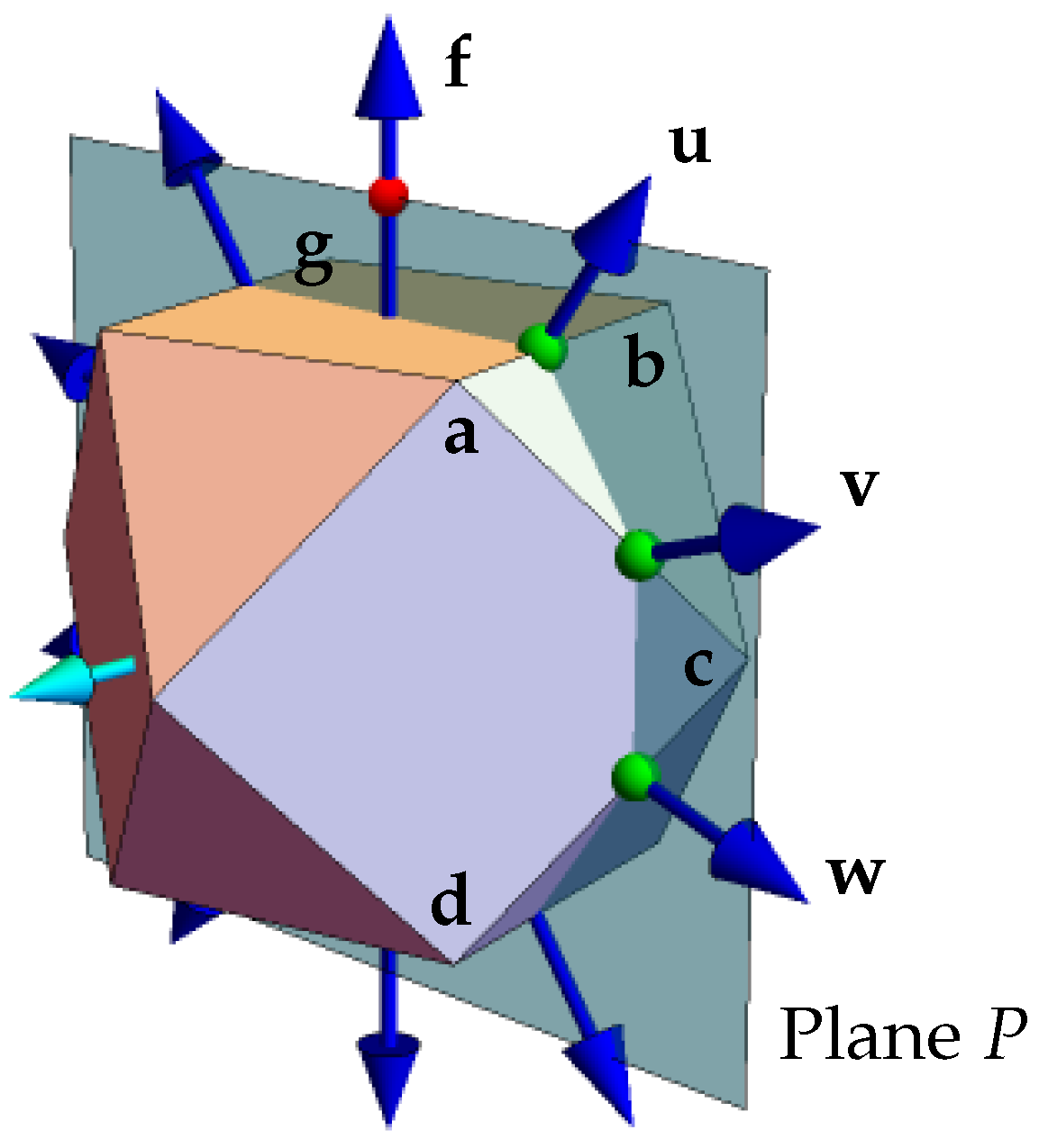
In the cuboctahedron, there are planes with a certain implicit 5-fold symmetry. Specifically, a plane through the centroid and containing the center of any square face may be oriented so that its intersections with the cuboctahedron edges are all equally spaced (
Figure 3). The vectors from the centroid to these edge intersections are then at intervals of
. Moreover, the two square face centers contained in this plane are also
from the nearest edge-intersections, so that the normalized vectors of edge intersections and face centers in this plane give the vertices of a regular decagon (a more detailed explanation and proof are provided in
Appendix A). Compounding by 5-fold rotations around this plane’s normal (
Figure 4) generates the C5C, which also has the requisite 2-fold and 3-fold symmetries (as well as 5-fold around other axes) that are needed for full icosahedral symmetry.
5. Rotations to a Single Cuboctahedron or to the C5C
To understand the effect of rotating cuboctahedra from different 24-cells into the same 3D space, we first look at a related question, which is how the different cuboctahedra can be generated by rotations from a single cuboctahedron in one space. We begin with a theorem about the left-isoclinic rotations on the compound of five 24-cells.
Theorem 1. Taking T as a compound of 24-cells (that is, considering the 24-cell facets, not the 600-cell facets), a left-isoclinic rotation that takes any one facet to any other will preserve the 24-cell partitioning; that is, the rotation may permute 24-cells, or permute vertices within 24-cells, but it will not mix vertices from distinct pre-rotation 24-cells into the same post-rotation 24-cell.
Proof. T is the orbit of under the cyclic action of , where each rotation creates a new 24-cell disjoint from the previous ones, until returns back to itself. Repeated actions of on the set must preserve the partitioning, since the first cycle creates the partitions and the action is cyclic.
Under powers of , the orbit of an initial facet f of is a set of five facets, one in each of the , and the orbits of distinct facets are disjoint. Therefore, to take f to any facet g in , one may first internally rotate , taking f to the in that has g in its orbit; one then simply applies . Since both and the internal rotation of preserve the 24-cell partitioning, the total rotation does as well.
It remains now to show that every rotation transferring one facet to another is equivalent to such a pair of rotations. But the facet normals of T are the vertices of F, hence the icosian group. All rotations between these are given by left- and right-multiplication by the members of the group. Furthermore, left-isoclinic rotations form a closed subgroup. Now, suppose , while g is in the orbit of , i.e., . Suppose also that is a rotation that stabilizes , such that . Then, , and multiplication on the right by yields . Thus, any left-isoclinic rotation h of the group can indeed be decomposed into an internal rotation of the initial 24-cell followed by a power of , which therefore preserves the partitioning of the . □
With this theorem, we show how quaternion rotations can take any facet in one 24-cell to any facet in any other 24-cell while preserving the 24-cell partitioning.
In
, we define the
primary normal, the
primary cuboctahedron, and the target 3D space
V for the rotations,
where the notation in (
11) for the cuboctahedron vertices should be self-explanatory (recalling that the
S refers to permutations). Note that
is normal to
and
V, as well as to the
facet
, whereby it is a vertex of
.
Now, let
q be a unit quaternion that rotates
to a facet normal
in
, i.e., to a vertex of
. Regarding these rotations, a few comments are in order. As mentioned previously, rotation by one-sided quaternionic multiplication is isoclinic, so that
q rotates in the
-plane as well as in its dual plane. With respect to applying
q on the left, we have the following variations. Since
, applying
on the left is of course the inverse rotation, giving the opposite rotation in both planes. Applying
on the right may be called the
-
converse of
q; it gives the same rotation in the
-plane, but the opposite rotation in the dual plane. Applying
on the right might be called the
-
contraverse, giving the opposite rotation in the
-plane, but the same rotation in the dual plane. Thus,
The converse and contraverse are defined with respect to a specific quaternion, here, ; in this case, they have particularly simple expressions, since commutes with any q.
According to Theorem 1, left multiplication by q or preserves the 24-cell groupings of the , and so it will preserve their duals, . This does not apply to right multiplication: it still preserves the complete F, since that is the icosian group, but it may mix the 24-cells, so it is not guaranteed to preserve their duals. Another way to think of this is to note that since multiplication on the right preserves F as a vertex set, it preserves the 600 facets of its convex hull as well, but the vertices of T are just a subset of that, and so they are not necessarily preserved.
Since left multiplication by
q takes
to
, and since it preserves the 24-cells, it will also take
to
, the cuboctahedron in
normal to
,
But
q is precisely one of the two natural rotations we identified in
Section 4—it is isoclinic, and the
-plane is one of its invariant planes, since
. And trivially, its inverse is the natural rotation that takes
to
, and will take
to
,
Thus, if we rotate the 3D space of to the target space V, the left-natural rotation will take exactly to , and the same argument applies to any of the cuboctahedra we choose in any of the 24-cells. Initially, thinking of rotating an arbitrary cuboctahedron of one 24-cell into the 3D space of some cuboctahedron in another 24-cell, it was not at all obvious that the two would end up exactly coinciding, but when viewed in light of the isoclinic construction by and of Theorem 1, this becomes almost trivial.
We come now to the other natural rotation, the right-isoclinic one. Let
Then, where is ? First, we know that this will live with in V, since returns to whether it acts on the right or the left. (Equivalently, one notes that two-sided multiplication by a unit quaternion and its conjugate rotates vectors in the 3D space normal to .) Second, the angle of q is the angle between and ; these are two vertices of the 600-cell F, and an exhaustive check of the angles between vertex vectors shows them all to be multiples of either , , or . The two-sided rotation by q and gives twice that angle, so it will be a multiple of , , or . These are the angles of icosahedral symmetry. Indeed, since left and right multiplication preserve the vertices of F, it must preserve their projection into V, which, as the vertex-first projection of a 600-cell, is icosahedrally symmetric. Thus, will be a rotation of around an icosahedral axis, either 5-fold, 3-fold, or 2-fold, according as the rotation angle from to is 10-fold, 6-fold, or 4-fold.
What we see here is that the vertices of the original compound of five 24-cells project as a facet-first 600-cell to tetrahedral symmetry (like the cuboctahedra), but that the facet normals project as a vertex-first 600-cell, with icosahedral symmetry; and that the converse isoclinic rotation which preserves the icosahedral symmetry of the facets must compound the cuboctahedra vertices in the correct way to give them icosahedral symmetry as well.
Finally, we note that there are, for example, six axes of 5-fold symmetry, and so from the above considerations, different cuboctahedra in
whose 3D spaces make
angles with
V could, in principle, end up within
V but in different orientations, rotated relative to
around different 5-fold axes. However, this is not the case. According to Theorem 1, with
p some internal isoclinic symmetry of
,
But
, since
p preserves
, while the two-sided quaternion action preserves
, and therefore also preserves the equator normal to
. The vertices of
will be permuted, but the cuboctahedron as a whole is preserved. Hence,
This is remarkable: does not actually depend on q, but only on , i.e., it does not depend on the choice of cuboctahedron within , but only on the fact that it comes from . Thus, all cuboctahedra of , under their natural respective right-isoclinic rotations into V, converge to the same cuboctahedron, just as they did under their respective left isoclinic rotations. In the left case, they all converge to , while in the right case, they converge to some orientation rotated from in an icosahedrally symmetric way. The same reasoning applies to cuboctahedra of each of the , with each being rotated by successive powers of , so that the four final cuboctahedra, together with , form the icosahedrally symmetric compound of five cuboctahedra.
Figure 5 illustrates this, showing cuboctahedra from five different 24-cells rotated into
V with varying amounts of their respective dual rotations (parameterized by
). The top and bottom rows show different arbitrary choices of initial cuboctahedra. One sees that under the direct rotation of each cuboctahedron to the primary space
V, with no dual rotation (
,
Figure 5c), they combine into an irregular jumble, with no non-trivial symmetry. Including each rotation’s dual, however, to make it isoclinic, one sees the compounds converge to a single cuboctahedron (
, left-isoclinic,
Figure 5e) or to the icosahedrally symmetric C5C (
, right-isoclinic,
Figure 5a). This happens irrespective of which cuboctahedral equator is chosen from each 24-cell to begin with, as illustrated by the two rows: under the direct rotations (
Figure 5c) they are completely different, but under the isoclinic rotations (
Figure 5a,e) they become the same. A manipulable visualization of this is available in the
supplementary material.
From these considerations—the naturalness of the chosen rotations, and the independence of the outcome from the specific choice of initial cuboctahedra—we feel justified in saying that the 600-cell, as a compound of five 24-cells, naturally induces the compounding of tetrahedral symmetries to icosahedral symmetry, as typified by the compound of five cuboctahedra.
The C5C and the 20G
We have seen in the previous section that the ESQC induces the C5C, and have elsewhere alluded to the connection between the C5C and the FIG’s 20G. To make this connection explicit, we first construct what we refer to as a 4-Group (4G). On a cuboctahedron, following
Figure 6, we select a disjoint set of four triangular faces (no shared vertices). We then create four tetrahedra by joining each triangle vertex to the cuboctahedron’s centroid and discarding cuboctahedron edges that do not belong to these tetrahedra. Since the circumradius of the cuboctahedron equals its edge length, the tetrahedra are regular.
Now, to construct the 20G, one combines five of these 4Gs using the same compounding process used to create the C5C—see
Figure 7, which follows the same process as
Figure 4 and yields a left-handed 20G. This process, as we have shown, comes from the compounding of 24-cells to make up the 600-cell, which in turn comes from the 5-fold fibration of 24-cells of the
A group in the Gosset
. (Note that in
Figure 6 one could have chosen the alternate set of triangular faces to make the 4G; doing so would have yielded the right-handed 20G seen in
Figure 2b. The choice of which to call “left” and “right’ is somewhat arbitrary here, but we note that if one points one’s left thumb along the compounding axis in
Figure 7, then one’s fingers wrap in the direction that appears to follow the pointing of the nearest tetrahedral vertices, so we call this one “left”.) Since a single 4G has the same convex hull as a single cuboctahedron (
Figure 6), compounding it 5-fold in the same manner as the C5C yields a set of vertices with the same convex hull as the C5C (
Figure 8).


