
Electrically Tunable Liquid Crystal Phase Grating with Double Period Based on the VIS Mode
Abstract
:1. Introduction
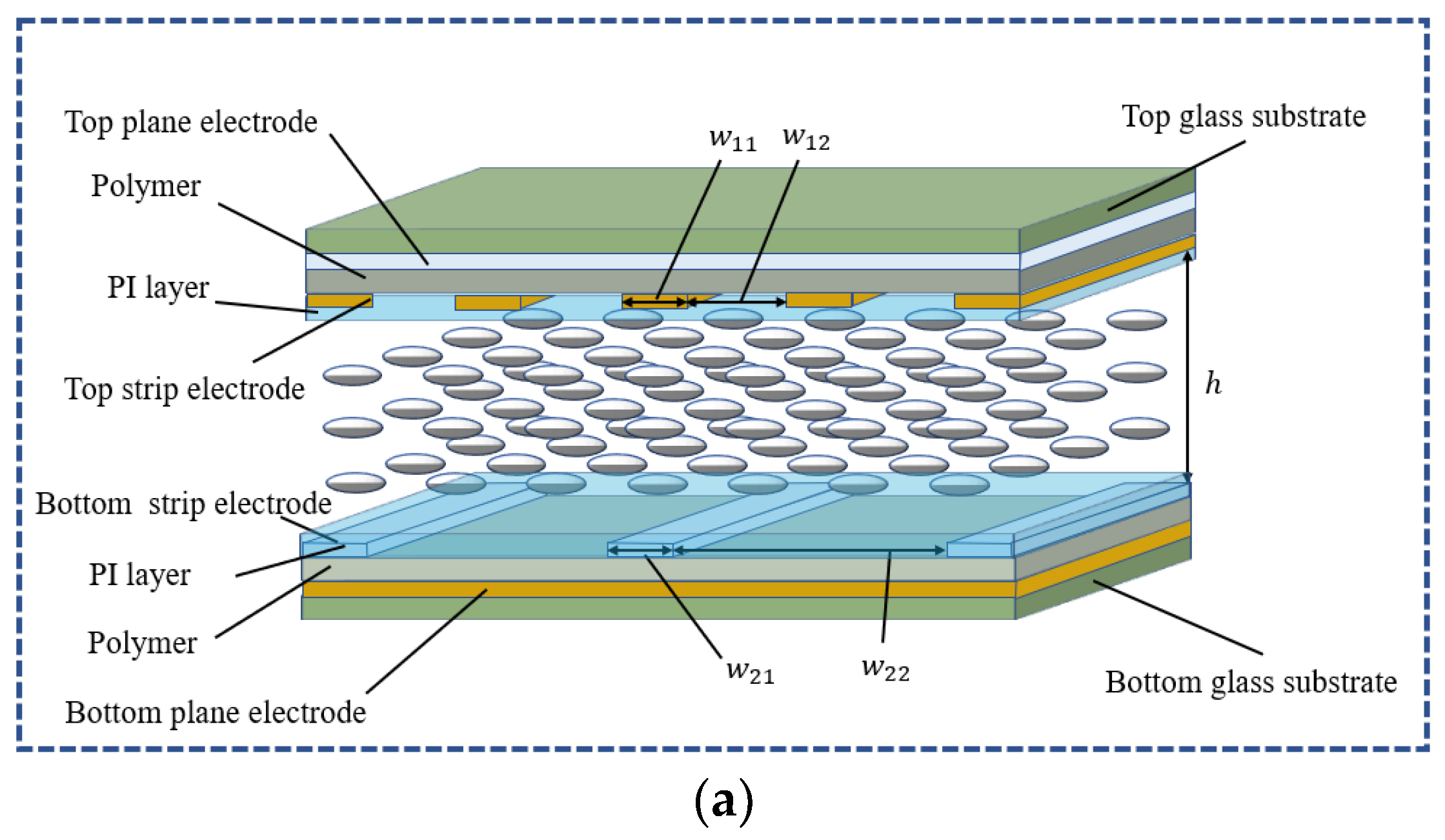
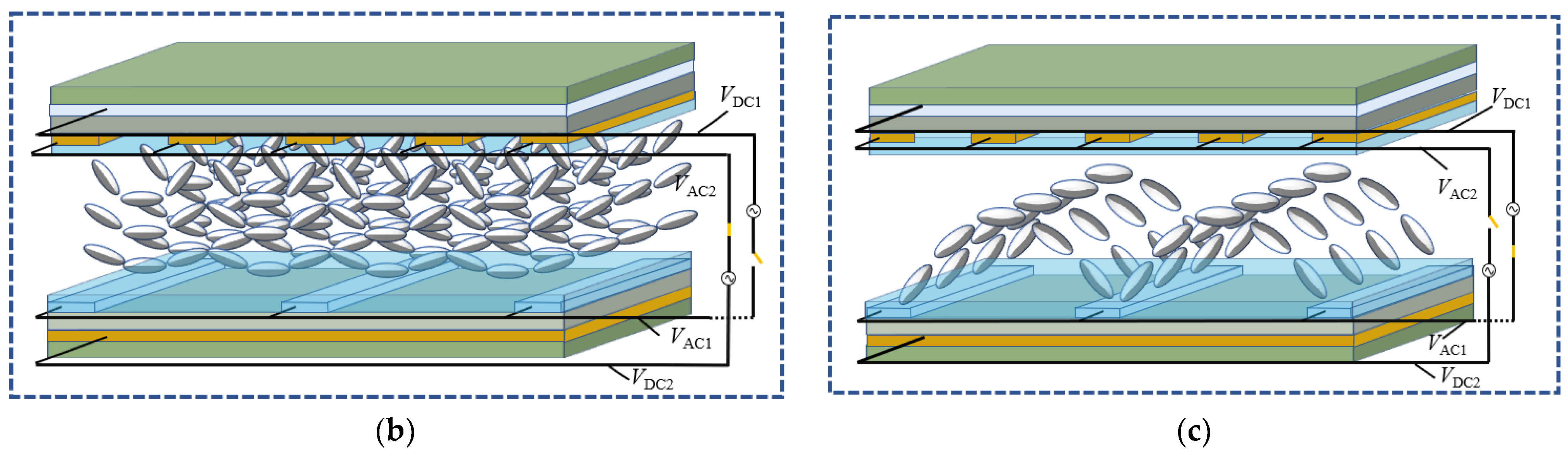
2. Device Structure and Principle
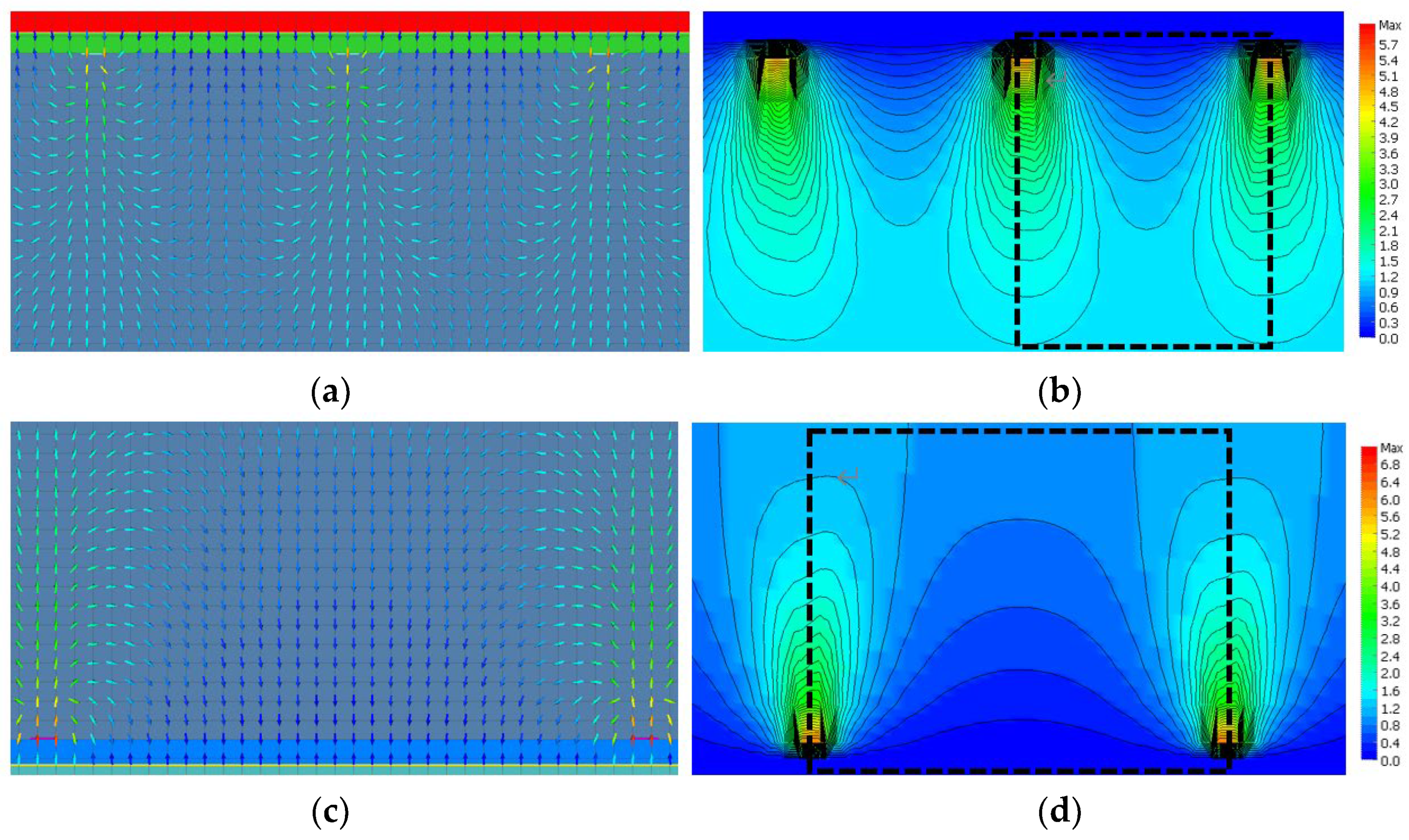
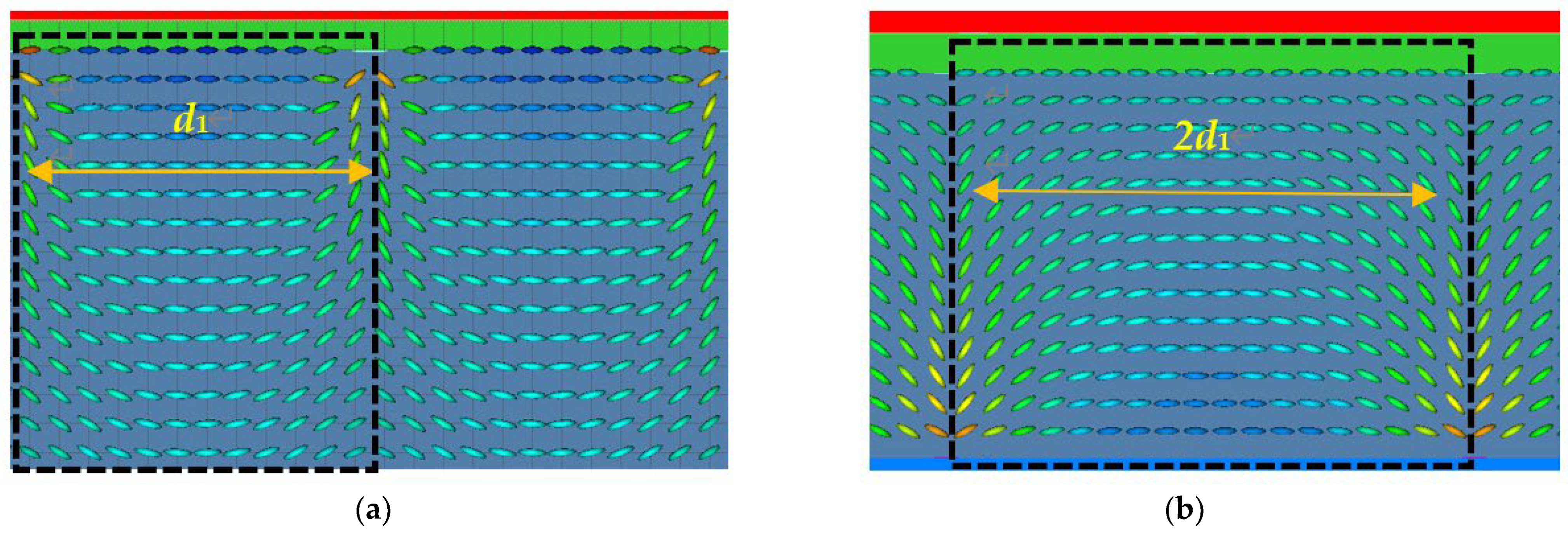
3. Simulation Results and Discussion
4. Materials and Methods
5. Conclusions
Author Contributions
Funding
Data Availability Statement
Conflicts of Interest
References
- Ren, H.; Shao, W.; Li, Y.; Salim, F.; Gu, M. Three-dimensional vectorial holography based on machine learning inverse design. Sci. Adv. 2020, 6, eaaz4261. [Google Scholar] [CrossRef] [PubMed] [Green Version]
- Lu, J.-G.; Sun, X.-F.; Song, Y.; Shieh, H.-P.D. 2-D/3-D Switchable Display by Fresnel-Type LC Lens. J. Disp. Technol. 2011, 7, 215–219. [Google Scholar] [CrossRef]
- Wakunami, K.; Hsieh, P.-Y.; Oi, R.; Senoh, T.; Sasaki, H.; Ichihashi, Y.; Okui, M.; Huang, Y.-P.; Yamamoto, K. Projection-type see-through holographic three-dimensional display. Nat. Commun. 2016, 7, 12954. [Google Scholar] [CrossRef] [PubMed] [Green Version]
- Wang, D.; Li, N.-N.; Li, Y.-L.; Zheng, Y.-W.; Nie, Z.-Q.; Li, Z.-S.; Chu, F.; Wang, Q.-H. Large viewing angle holographic 3D display system based on maximum diffraction modulation. Light Adv. Manuf. 2023, 4, 18. [Google Scholar] [CrossRef]
- Shi, L.; Li, B.; Kim, C.; Kellnhofer, P.; Matusik, W. Towards real-time photorealistic 3D holography with deep neural networks. Nature 2021, 591, 234–239. [Google Scholar] [CrossRef]
- Ghaith, M.; Özgün, Y.; Kesim, D.K.; Ahmet, T.; Parviz, E.; Serim, L.; Llday, T.O. Breaking crosstalk limits to dynamic holog-raphy using orthogonality of high-dimensional random vectors. Nat. Photonics 2019, 13, 251–256. [Google Scholar]
- Peng, Y.; Choi, S.; Kim, J.; Wetzstein, G. Speckle-free holography with partially coherent light sources and camera-in-the-loop calibration. Sci. Adv. 2021, 7, eabg5040. [Google Scholar] [CrossRef]
- Gao, H.; Wang, Y.; Fan, X.; Jiao, B.; Li, T.; Shang, C.; Zeng, C.; Deng, L.; Xiong, W.; Xia, J.; et al. Dynamic 3D meta-holography in visible range with large frame number and high frame rate. Sci. Adv. 2020, 6, eaba8595. [Google Scholar] [CrossRef]
- Park, J.; Lee, K.; Park, Y. Ultrathin wide-angle large-area digital 3D holographic display using a non-periodic photon sieve. Nat. Commun. 2019, 10, 1304. [Google Scholar] [CrossRef] [Green Version]
- Li, Q.; Li, Y.; Ma, J.; Yang, D.-K.; White, T.J.; Bunning, T.J. Directing Dynamic Control of Red, Green, and Blue Reflection Enabled by a Light-Driven Self-Organized Helical Superstructure. Adv. Mater. 2011, 23, 5069–5073. [Google Scholar] [CrossRef] [PubMed]
- Gilardi, G.; De Sio, L.; Beccherelli, R.; Asquini, R.; D’alessandro, A.; Umeton, C. Observation of tunable optical filtering in photosensitive composite structures containing liquid crystals. Opt. Lett. 2011, 36, 4755–4757. [Google Scholar] [CrossRef]
- Xu, D.; Tan, G.; Wu, S.-T. Large-angle and high-efficiency tunable phase grating using fringe field switching liquid crystal. Opt. Express 2015, 23, 12274–12285. [Google Scholar] [CrossRef] [PubMed] [Green Version]
- Chen, J.; Bos, P.J.; Vithana, H.; Johnson, D.L. An electro & hyphen optically controlled liquid crystal diffraction grating. Appl. Phys. Lett. 1995, 67, 2588–2592. [Google Scholar]
- Friedman, L.J.; Hobbs, D.S.; Lieberman, S.; Corkum, D.L.; Nguyen, H.Q.; Resler, D.P.; Sharp, R.C.; Dorschner, T.A. Copy-right 2006 society of photo instrumentation engineers. Proc. IEEE 1996, 84, 268–298. [Google Scholar]
- Dou, H.; Wang, L.; Xu, L.-P.; Mao, X.; Ou, J.-Y.; Nie, J.-Y.; Wang, S.-R.; Wang, S.; Dan, Y.-Q. Directional modulated light-emitting technology based on airborne display. Liq. Cryst. 2022, 49, 2146–2154. [Google Scholar] [CrossRef]
- Ren, H.; Fan, Y.-H.; Wu, S.-T. Prism grating using polymer stabilized nematic liquid crystal. Appl. Phys. Lett. 2003, 82, 3168–3170. [Google Scholar] [CrossRef]
- Algorri, J.F.; Urruchi, V.; Bennis, N.; Sánchez-Pena, J.M. Cylindrical liquid crystal micro-lens array with rotary axis and tunable capability. IEEE Electron Device Lett. 2015, 36, 582–584. [Google Scholar] [CrossRef]
- Chu, F.; Guo, Y.-Q.; Zhang, Y.-X.; Duan, W.; Zhang, H.-L.; Tian, L.-L.; Li, L.; Wang, Q.-H. Four-mode 2D/3D switchable display with a 1D/2D convertible liquid crystal lens array. Opt. Express 2021, 29, 37464–37475. [Google Scholar] [CrossRef]
- Gilardi, G.; Asquini, R.; D’Alessandro, A.; Beccherelli, R.; De Sio, L.; Umeton, C. All-Optical and Thermal Tuning of a Bragg Grating Based on Photosensitive Composite Structures Containing Liquid Crystals. Mol. Cryst. Liq. Cryst. 2012, 558, 64–71. [Google Scholar] [CrossRef]
- Chang, C.; Bang, K.; Wetzstein, G.; Lee, B.; Gao, L. Toward the next-generation VR/AR optics: A review of holographic near-eye displays from a human-centric perspective. Optica 2020, 7, 1563–1578. [Google Scholar] [CrossRef]
- Blanche, P.-A. Holography, and the future of 3D display. Light Adv. Manuf. 2021, 2, 28. [Google Scholar] [CrossRef]
- Yu, H.; Lee, K.; Park, J.; Park, Y. Ultrahigh-definition dynamic 3D holographic display by active control of volume speckle fields. Nat. Photonics 2017, 11, 186–192. [Google Scholar] [CrossRef]
- Simeon, S.; Margarita, M.; Marga, P.; Dimitar, T. Holographic diffraction grating controlled by means of nematic liquid crystal. Mol. Cryst. 1987, 152, 609–615. [Google Scholar]
- Dou, H.; Wang, L.; Ren, G.; Dan, Y.-Q.; Zhong, X.-T.; Ou, J.-Y.; Yuan, J.-Y.; Zhong, Y.-T. A Light-Mixing Liquid Crystal Lens-Like Cell to Decrease Color Shift and Tune Brightness for Displays. Crystals 2022, 12, 213. [Google Scholar] [CrossRef]
- Caputo, R.; De Sio, L.; Veltri, A.; Umeton, C.; Sukhov, A.V. Development of a new kind of switchable holographic grating made of liquid-crystal films separated by slices of polymeric material. Opt. Lett. 2004, 29, 1261–1263. [Google Scholar] [CrossRef]
- Gu, L.; Chen, X.; Jiang, W.; Howley, B.; Chen, R.T. Fringing-field minimization in liquid-crystal-based high-resolution switchable gratings. Appl. Phys. Lett. 2005, 87, 201106. [Google Scholar] [CrossRef]
- Wang, B.; Ye, M.; Sato, S. Liquid Crystal Negative Lens. Jpn. J. Appl. Phys. 2005, 44, 4979–4983. [Google Scholar] [CrossRef]
- Dou, H.; Chen, M.; Li, D.; Yu, G.; Sun, Y.-B. A controllable viewing angle optical film using micro prisms filled with liquid crystal. Liq. Cryst. 2021, 48, 1373–1381. [Google Scholar] [CrossRef]
- Lien, A. The general and simplified Jones matrix representations for the high pretilt twisted nematic cell. J. Appl. Phys. 1990, 67, 2853–2856. [Google Scholar] [CrossRef]
- Li, J.-N.; Hu, X.-K.; Wei, B.-Y.; Wu, Z.-J.; Ge, S.-J.; Ji, W.; Hu, W.; Lu, Y.-Q. Simulation and optimization of liquid crystal gratings with alternate twisted nematic and planar aligned regions. Appl. Opt. 2014, 53, E14–E18. [Google Scholar] [CrossRef] [Green Version]
- Magnusson, R.; Gaylord, T.K. Diffraction efficiencies of thin phase gratings with arbitrary grating space. J. Opt. Soc. Am. A. 1978, 68, 806–809. [Google Scholar] [CrossRef]
- Xiong, J.; Hsiang, E.-L.; He, Z.; Zhan, T.; Wu, S.-T. Augmented reality and virtual reality displays: Emerging technologies and future perspectives. Light Sci. Appl. 2021, 10, 216. [Google Scholar] [CrossRef] [PubMed]
- Kowerdziej, R.; Wróbel, J.; Kula, P. Ultrafast electrical switching of nanostructured metadevice with dual-frequency liquid crystal. Sci. Rep. 2019, 9, 20367. [Google Scholar] [CrossRef] [PubMed] [Green Version]
- Golovin, A.B.; Shiyanovskii, S.V.; Lavrentovich, O.D. Fast switching dual-frequency liquid crystal optical retarder, driven by an amplitude and frequency modulated voltage. Appl. Phys. Lett. 2003, 83, 3864–3866. [Google Scholar] [CrossRef]
- Xianyu, H.; Wu, S.-T.; Lin, C.-L. Dual frequency liquid crystals: A review. Liq. Cryst. 2009, 36, 717–726. [Google Scholar] [CrossRef]
- Yan, J.; Li, Y.; Wu, S.-T. High-efficiency and fast-response tunable phase grating using a blue phase liquid crystal. Opt. Lett. 2011, 36, 1404–1406. [Google Scholar] [CrossRef] [Green Version]


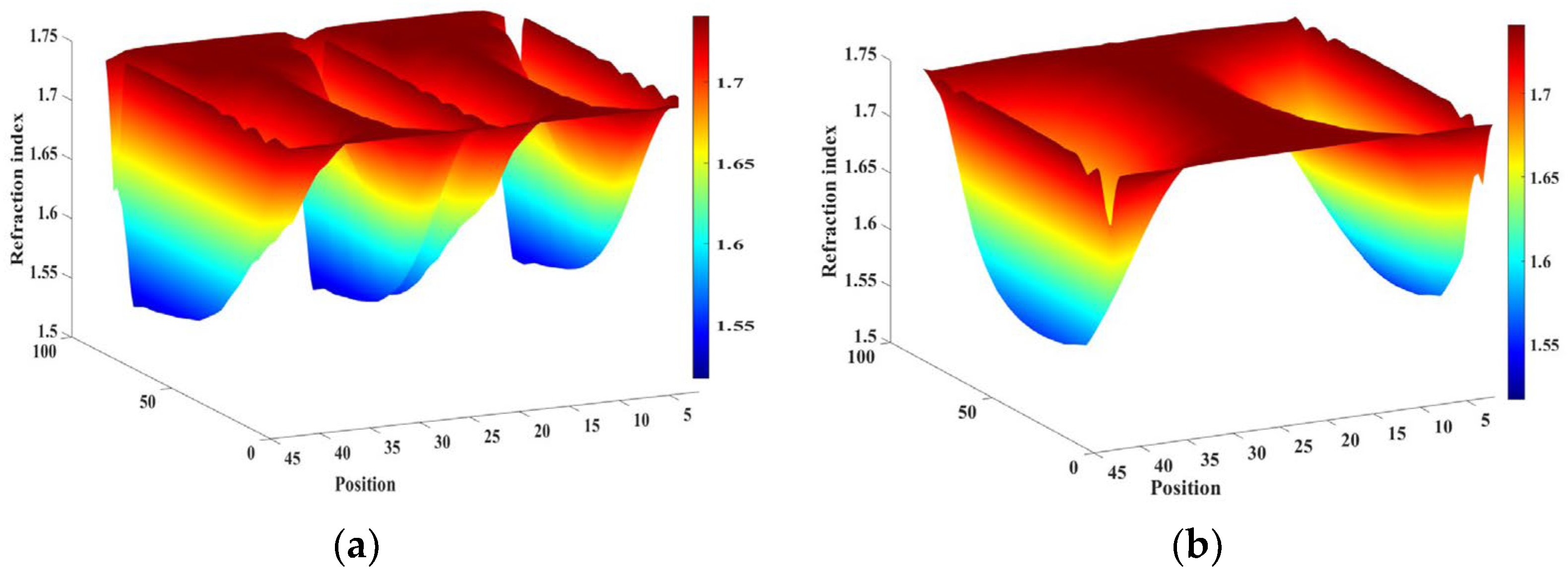
| Material | ∆n | ∆ε | γ | K11 | K22 | K33 | ne | no |
|---|---|---|---|---|---|---|---|---|
| E7-LC | 0.224 | 11.4 | 29 mPa·s | 16.7 pN | 7.3 pN | 18.1 pN | 1.741 | 1.517 |
| Type | Gap | Width | d | h | Periodic Order |
|---|---|---|---|---|---|
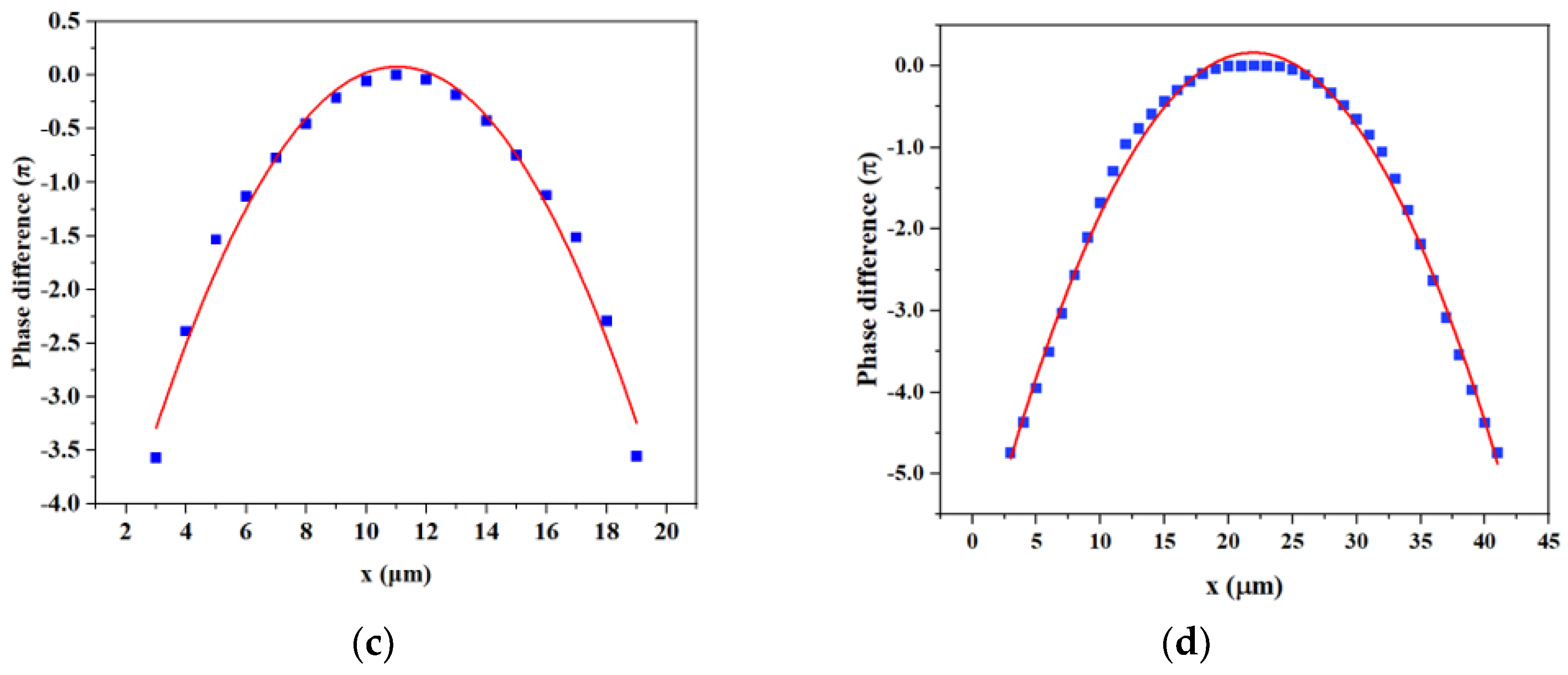
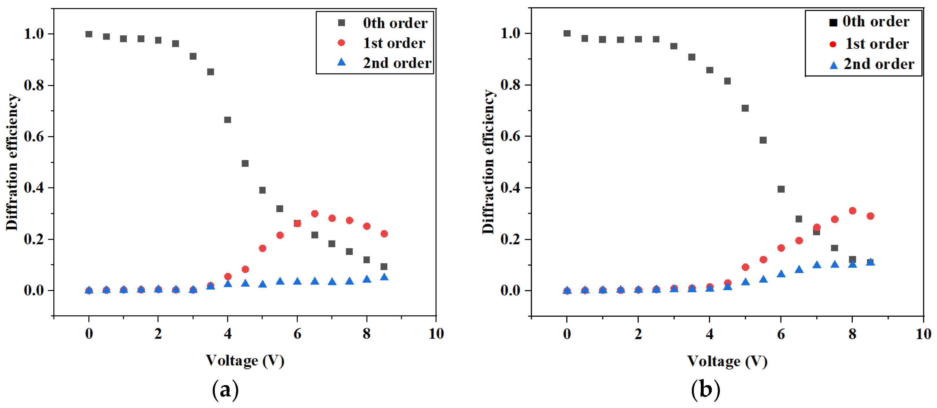
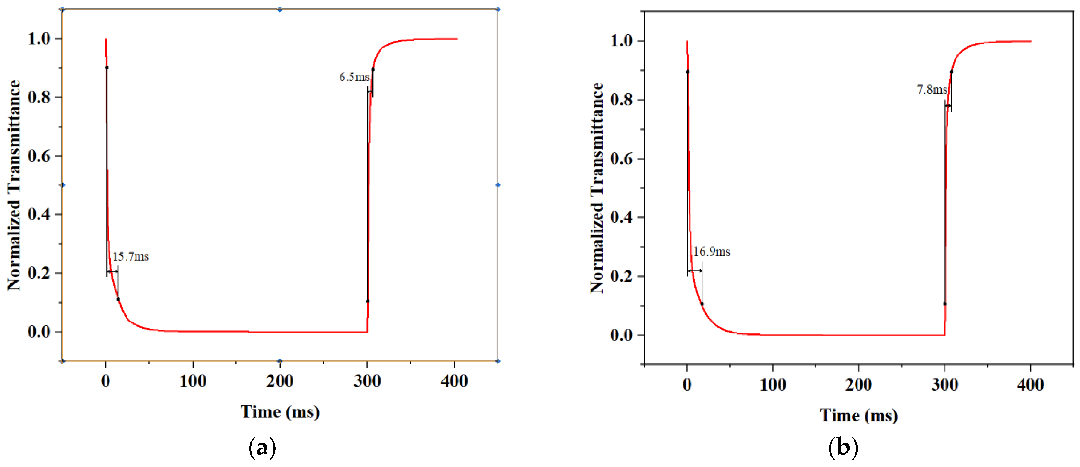
| 1 | w12 = 18 μm | w11 = 2 μm | 20 μm | 10 μm | Small |
| 2 | w22 = 38 μm | w21 = 2 μm | 40 μm | 10 μm | Large |
Disclaimer/Publisher’s Note: The statements, opinions and data contained in all publications are solely those of the individual author(s) and contributor(s) and not of MDPI and/or the editor(s). MDPI and/or the editor(s) disclaim responsibility for any injury to people or property resulting from any ideas, methods, instructions or products referred to in the content. |
© 2023 by the authors. Licensee MDPI, Basel, Switzerland. This article is an open access article distributed under the terms and conditions of the Creative Commons Attribution (CC BY) license (https://creativecommons.org/licenses/by/4.0/).
Share and Cite
Guo, Z.; Li, Y.; Zeng, Y.-M.; Yu, L.; Tian, L.-L. Electrically Tunable Liquid Crystal Phase Grating with Double Period Based on the VIS Mode. Crystals 2023, 13, 1235. https://doi.org/10.3390/cryst13081235
Guo Z, Li Y, Zeng Y-M, Yu L, Tian L-L. Electrically Tunable Liquid Crystal Phase Grating with Double Period Based on the VIS Mode. Crystals. 2023; 13(8):1235. https://doi.org/10.3390/cryst13081235
Chicago/Turabian StyleGuo, Zhou, Yao Li, Yu-Meng Zeng, Le Yu, and Li-Lan Tian. 2023. "Electrically Tunable Liquid Crystal Phase Grating with Double Period Based on the VIS Mode" Crystals 13, no. 8: 1235. https://doi.org/10.3390/cryst13081235