Article

Mechanical Analysis and Testing of Conduction-Cooled Superconducting Magnet for Levitation Force Measurement Application

1
School of Automation, Chengdu University of Information Technology, Chengdu 610225, China
2
School of Intelligent Manufacturing and Electronic Engineering, Wenzhou University of Technology, Wenzhou 325035, China
3
Superconductor and New Energy R&D Center, Southwest Jiaotong University, Chengdu 610031, China
4
College of Physics and Energy, Fujian Normal University, Fuzhou 350117, China
*
Authors to whom correspondence should be addressed.
Crystals 2023, 13(7), 1117; https://doi.org/10.3390/cryst13071117
Submission received: 3 June 2023 / Revised: 13 July 2023 / Accepted: 15 July 2023 / Published: 17 July 2023
(This article belongs to the Special Issue Research on High-Temperature Superconducting Materials)

Abstract

:
High-temperature superconductors have great potential for various engineering applications such as a flywheel energy storage system. The levitation force of bulk YBCO superconductors can be drastically increased by increasing the strength of the external field. Therefore, a 6T conduction-cooled superconducting magnet has been developed for levitation force measurement application. Firstly, to protect the magnet from mechanical damage, reliable stress analysis inside the coil is paramount before the magnet is built and tested. Therefore, a 1/4 two-dimensional (2D) axisymmetric model of the magnet was established, and the mechanical stress in the whole process of winding, cooling down and energizing of the magnet was calculated. Then, the charging, discharging, and preliminary levitation force performance tests were performed to validate the operating stability of the magnet. According to the simulation results, the peak stresses of all coil models are within the allowable value and the winding maintains excellent mechanical stability in the superconducting magnet. The test results show that the superconducting magnet can be charged to its desired current of 150 A without quenching and maintain stable operation during the charging and discharging process. What is more, the superconducting magnet can meet the requirements for the levitation force measurement of both low magnetic field and high magnetic field.

1. Introduction

Due to zero resistance, the Meissner effect, and flux-pinning properties, high-temperature superconductors (HTSs) have great potential for various engineering applications, such as flywheel energy storage devices [1,2,3]. The appearance of YBCO bulk material gave a great boost to applications in the field of levitation [4,5]. The levitation force of YBCO bulk is achieved by the interaction between the external magnetic and the YBCO superconductor [6,7]. In these applications, the external magnetic is always provided by permanent magnets (PMs) [8]. However, the magnetic field strength and gradient of PMs are the key factor restricting the levitation forces of HTSs [9]. Superconducting magnets have the great advantage of offering higher magnetic field intensity compared with traditional PMs; utilizing a superconducting magnet as magnetic field source can obtain much greater levitation force than PMs. Under a high background magnetic field, some new properties are obtained which could not be observed in PMs’ magnetic fields [10,11,12]. To promote more profound understanding of the interaction mechanisms between HTSs and high external magnetic fields, a levitation force measurement system composed of a 6T NbTi conduction-cooled superconducting magnet has been built in our laboratory.
The inward radial stresses are induced by the winding tension, when the superconducting wires are wound on the bobbin in tension [13]. However, the filaments of superconducting wires may generate micro cracking if the pretension stress is much higher. After cooling down from room temperature to operating temperature, the superconducting magnet is inward contraction. The thermal stresses are generated due to the different coefficient of thermal expansion among the different components of magnet structure. When the magnet is charged up to its designed working current, it is noteworthy that non-negligible Lorentz force will be generated on the coils under high field conditions. However, the performance of superconducting magnet is easy to suffer from an undesirable degradation, if the stresses in the magnet structure are over the maximum allowable values [14]. The degradation is a great threaten for magnet operation and must be carefully prevented from happening. Considering the importance of this aspect, a detailed mechanical analysis is demanded for designing the superconducting magnet [15,16,17,18].
The pretension stress of the solenoid magnet is conventionally calculated adopting the thick cylinder approach [19], however, it is not possible to predict the interlayer stress state of the coils. In recent years, thanks to the wide application of finite element analysis (FEA), FEA has been used for accurate modeling in the mechanical analysis and magnetic field design of superconducting magnets. In every design step, the geometric model, material properties, boundary conditions and adaptive mesh are set in sequence, and then the partial differential equations are solved [20]. The element birth and death method is widely used in the calculation of winding process in a magnet [21,22]. By using an FEA program, the thermal and structural calculations are prone to be carried out along with the element birth and death method [23]. Besides, the Lorentz forces can be computed by the traditional Biot-Savart equations [24], as well as the commercial software based on the Maxwell equations [25]. However, there are few literatures to study the comprehensive effect of the winding pretension and the bandage, thermal, and electromagnetic forces in the superconducting magnet. What is more, preliminary testing of the system is necessary before the levitation force measurement system is put into normal use.
The purpose of this paper is to investigate in detail the mechanical behavior and preliminary performance testing of the system. According to the working conditions of superconducting magnets, the mechanical stress of the NbTi coil is discussed from the aspect of multi-load steps. The operating stability of superconducting magnets and the levitation force performance of YBCO bulk are preliminarily studied. This paper is organized as follows. In Section 2, the structure of the conduction-cooled superconducting magnet for levitation force measurement application is described; Section 3 establishes the simulation model of the superconducting magnet, focusing on the calculation of the mechanical stress in the NbTi solenoid coil assembly; Section 3.1 presents the detailed features of the superconducting magnet model; Section 3.2 provides the equivalent material properties of the NbTi composite conductor; Section 3.3 describes the loads that were applied to the structural model in sequence; Section 3.4 describes the theoretical modeling and fundamental equations; Section 4 discusses the simulation results for the superconducting magnet; Section 4.1 discusses the magnetic field and electromagnetic force of the superconducting magnet; Section 4.2 discusses the mechanical stress on the magnet during the whole process; Section 5 investigates the operating stability of the superconducting magnet; Section 6 discusses the levitation force performance of YBCO bulk under the measurement range from 190 mm to 90 mm at different exciting current; finally, the main conclusions are given in Section 7.

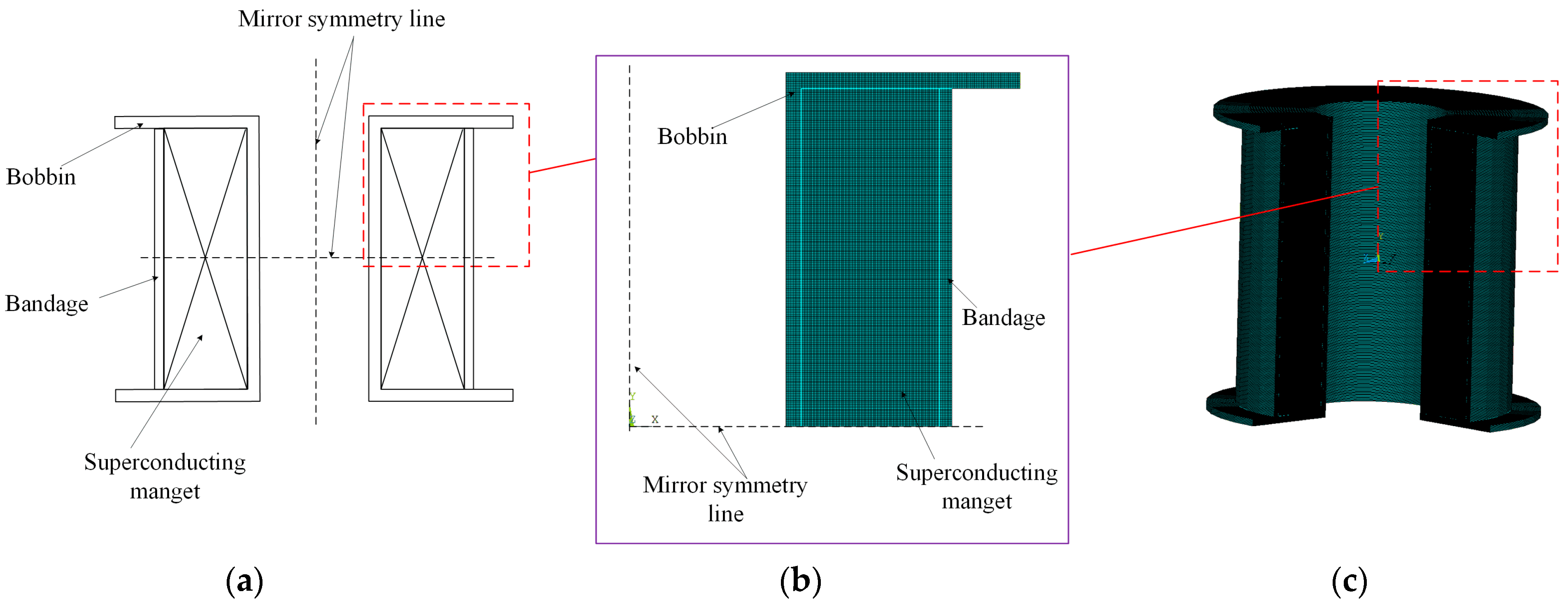
2. The Structure of the Conduction-Cooled Superconducting Magnet for Levitation Force Measurement Application

The superconducting magnet has a room temperature bore with diameter of 50 mm. The levitation force measurement system mainly consists of a superconducting magnet, a liquid nitrogen container, a displacement sensor, and a force sensor connected the YBCO bulk through an insulation rod. The actual structure and schematic illustration are shown in Figure 1.
The superconducting magnet composes by an NbTi solenoid coil which is cooled down to 4,2K by conduction-cooled method using a two-stage GM cry-ocooler (RDK-408D, Sumitomo Heavy Industries, Ltd., Japan.). The two-stage GM cryocooler is integrated into the cryostat for magnet cooling. It takes approximately 31 h to cool down the superconducting magnet to the final temperature. The room temperature bore is used to place the liquid nitrogen container, which is fixed directly to the superconducting magnet. The displacement sensor is used to measure the distance of z, where z is the distance from the magnet center baseline (z = 0), as shown in Figure 1b. The high-temperature superconductor employs YBCO material and uses liquid nitrogen for cooling to obtain the superconducting state. The YBCO bulk sample fabricated by a top-seeded melt-textured-growth process is with a diameter of 30 mm and a thickness of 18 mm [26].

3. Numerical Model of the Superconducting Magnet

3.1. Model Description of the Superconducting Magnet

When energizing up to 150 A current after cooling down to 4.2 K, the superconducting magnet which is made of a NbTi solenoid coil can generate a 6 T magnetic field strength. The main parameters of the NbTi coil are summarized in Table 1.
The structural model of the magnet is shown in Figure 2a. The copper bobbin is used to support the coil, and the aluminum bandage is applied to maintain the mechanical integrity of the magnet. In order to obtain an accurate result for the winding pre-stress, each layer of coil and bandage is assumed to be a rectangular strip, and each turn of the coils is regarded as an element. As the magnet geometry and loading are both mirror symmetry, only a 1/4 two-dimensional (2D) axisymmetric model has been modeled to simulate the magnetic and mechanical behavior of the superconducting magnet based on the FEA program ANSYS [27]. The 1/4 two-dimensional (2D) axisymmetric mesh model is depicted in Figure 2b, and X, Y, and Z represent the radial, axial, and circumferential directions, respectively. The 1/4 two-dimensional axisymmetric model can be expanded to a three-dimensional (3D) model as shown in Figure 2c. The computations can be simplified by introducing several assumptions in the model: (1) any two in-contact surfaces are considered to be perfectly bonded; (2) the temperature of the whole magnet is kept uniform in the cooling process; (3) all structural materials are considered to be maintained elastic properties.

3.2. Equivalent Material Properties

The NbTi superconductor is a composite material which is constituted of copper, NbTi alloy, and insulation materials. Modeling each conductor’s components leads to modeling difficulty and is time-consuming for computation. However, the different materials of the superconducting coil can be treated as homogeneous orthotropic materials, whose equivalent material properties can be approximately obtained by homogenization techniques based on a finite element method [28,29,30]. The materials constituting the conductor as well as the support structure’s materials are given in Table 2 [31,32].
Using the property data of coil material given in Table 2, the equivalent material properties of the coil were obtained through the homogenization method [33,34], where E, ν, G, and αΔT represent the Young’s module, Poisson ratio, shear module, and thermal contraction from 293 K to 4.2 K, respectively. The results are listed in Table 3, where the material properties of the coil are substituted by the equivalent material properties.

3.3. Load Sources of Superconducting Magnet

The mechanical stress has significant influence on the properties of superconducting magnets. Three successive loads are included in the coil model: (1) Pre-stress after winding with 60 MPa tension on coil and bandage at room temperature. An element birth and death method is adopted to calculate the mechanical behavior of winding. The element death means that the stiffness matrix of the element is deactivated by multiplying by a small factor instead of deleting all coil assembly elements from the model, and then the associated loads and mass parameters of the dead elements are set to zero. While the element birth means reactivating all the elements by deleting the small factor [21,22]. (2) Thermal stress after cooling down from 300 K to 4.2 K. The whole coil model was applied with thermal gradient of 295.8 K, and the temperature distribution throughout the cooling process was regarded as uniform. (3) Electromagnetic stress in the coil after charging to target current of 150 A. The Lorentz forces which were transferred to the coil model can be calculated from the magnetic field distribution.

3.4. Theoretical Modeling and Fundamental Equations

In the process of winding preload on the NbTi superconducting wire to prepare high-field coils, NbTi superconducting wires are affected by the elastic deformation caused by the tensile load on the winding. The mechanical governing equation of coil during the winding process can be derived from the stress balance equation [35]:
r 2 2 σ r r 2 + 3 r σ r r + σ r ( 1 E φ E r ) = 0 ,
where E r and E φ are the radial and circumferential Young’s moduli, respectively. After N-layer coil is wound on the bobbin, the radial stress of mth layer is the accumulation of the radial stress generated by N-m layers. The hoop stress in the mth layer is the accumulation of winding tension applied on the mth layer and the hoop stress generated by winding N-m layers. Therefore, the radial and hoop stresses of mth layer can be estimated by:
σ r , m = l = m + 1 N σ r , m l ,   σ φ , m = σ 0 + l = m + 1 N σ φ , m l ,    
where σ 0 is the winding tensile stress. In the winding process, a constant winding stress of 60 Mpa was applied. The bobbin was with 5 mm thickness.
There is a large temperature variation in the process of cooling the magnet from room temperature (300 K) to the operating temperature (4.2 K), and the thermal strain caused by the temperature variation can be indicated as [36]:
ε t h , i = α i ( T o T r )   ( i = r , φ , z ) ,
where To is the operating temperature (4.2 K), Tr is the room temperature (300 K), and α i is the coefficient of thermal expansion along the i direction of the magnet.
In the energizing process, the equilibrium-governing equations of the magnet subjected to the electromagnetic force generated by the Lorentz force are given by [37,38,39]:
σ r r + τ z r z + σ r σ φ r + f r = 0 ,   σ z z + τ r z r + τ r z r + f z = 0 ,  
where σ r , σ φ , and σ z are the radial, circumferential, and axial stresses. τ z r   is the shear stress along zr plane. The body forces f r and f z represent the radial and axial electromagnetic forces, respectively, which can be expressed as:
f r   =   J φ B z , f z   =   J φ B r ,
where J φ is the circumferential current density of the coil. Br and Bz represent the radial and axial magnetic fields, respectively.
The strain–stress constitutive equation can be expressed as [40]:
ε r = σ r E r ν φ r σ φ E φ ν z r σ z E z + α r ( T r T o ) , ε φ = ν r φ σ r E r + σ φ E φ ν z φ σ z E z + α φ ( T r T o ) , ε z = ν r z σ r E r ν φ z σ φ E φ σ z E z + α z ( T r T o ) , γ r φ = τ r φ G r φ ,   γ r z = τ r z G r z ,   γ φ z = τ φ z G φ z ,
where ν and G are the e Poisson’s ratio and shear modulus, respectively.
The corresponding boundary conditions of the coil can be expressed as:
( σ r , τ r z ) r = r i n , r o u t = 0 ,   ω z = z u p , z l o w = 0 .
where w represents the axial displacements.
The finite element method based on the homemade procedure combined with ANSYS software is used to solve the whole numerical model. In numerical simulations, it is extremely inefficient to use the original dimensions for calculation. Therefore, the equivalent material properties based on the homogenization method were calculated, and the result is shown in Table 3.

4. Simulation Results of the Superconducting Magnet

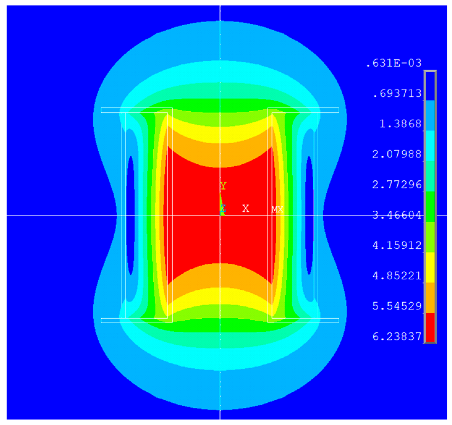
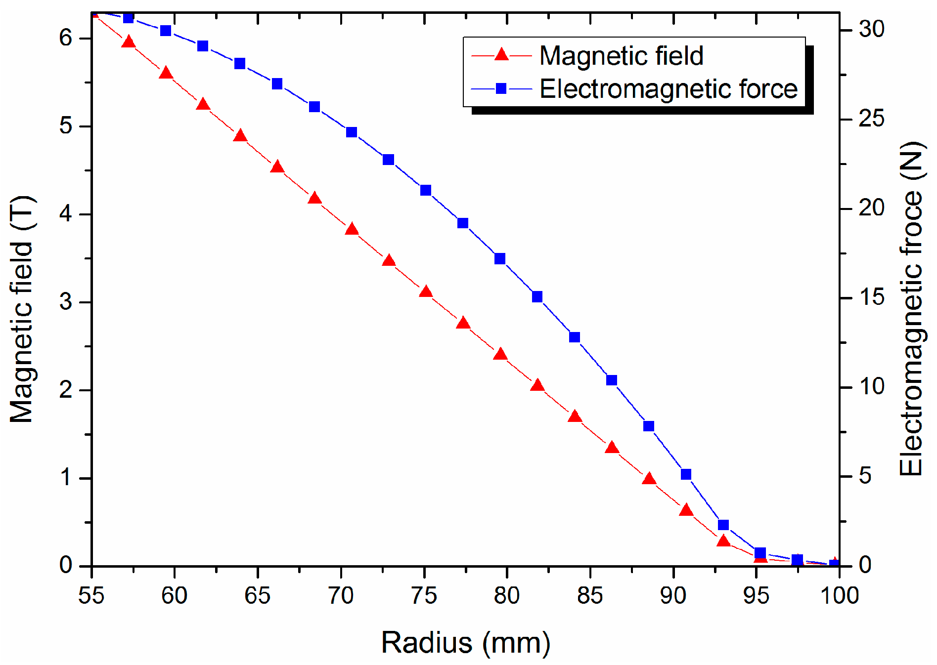
4.1. Magnetic Field Analysis of the Superconducting Magnet

The coupled field element (PLANE13) and the infinite boundary element (INFIN110) is used for the 2-D magnetic field model to calculate the magnetic fields [33]. When energizing up to the operation current of 150 A, the magnetic field distribution of the magnet is plotted in Figure 3. The magnetic field of 6 T is generated at the center of the coil, and the maximum magnetic field can reach 6.23 T at the innermost layer of the coil.
Figure 4 presents the magnetic field and electromagnetic force as functions of the radius in the coil mid-plane. It shows that the electromagnetic force reduces with the decrease in magnetic field.

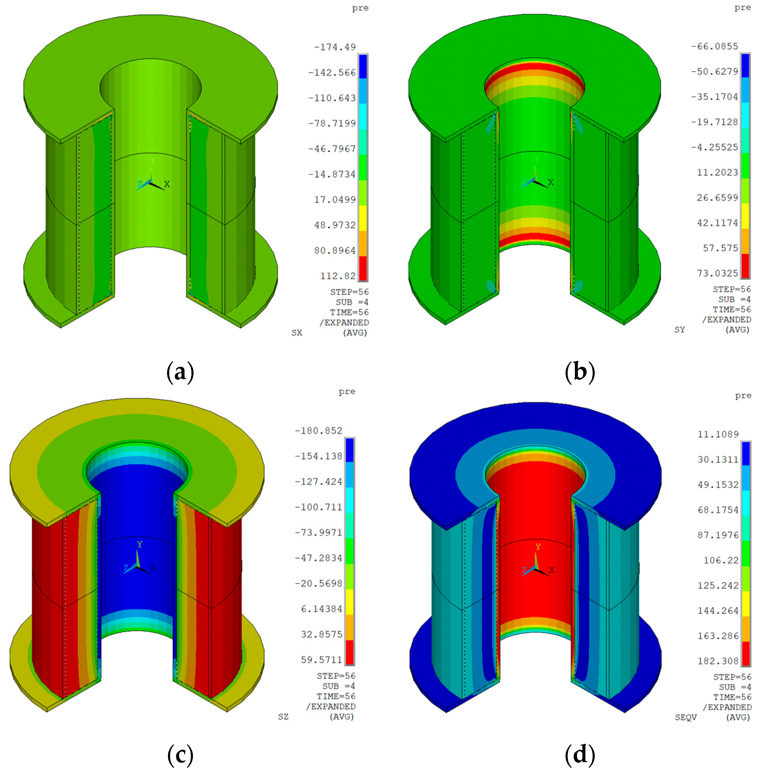
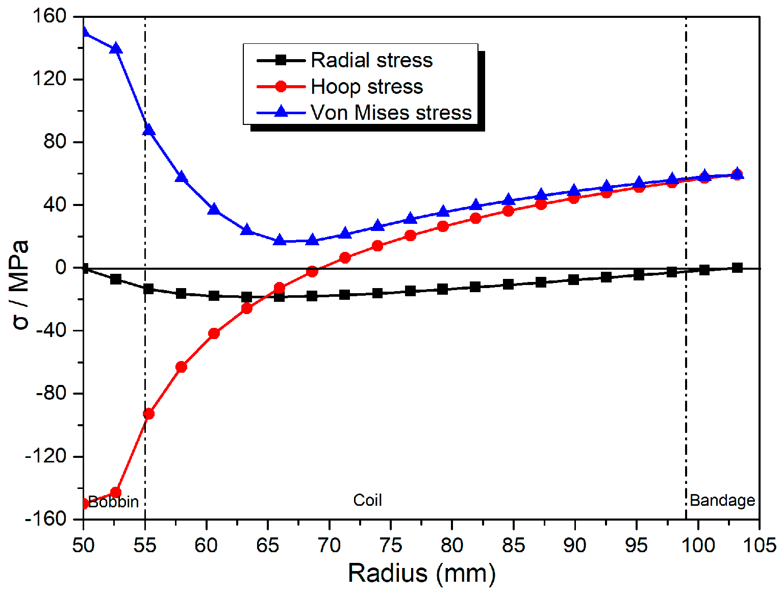
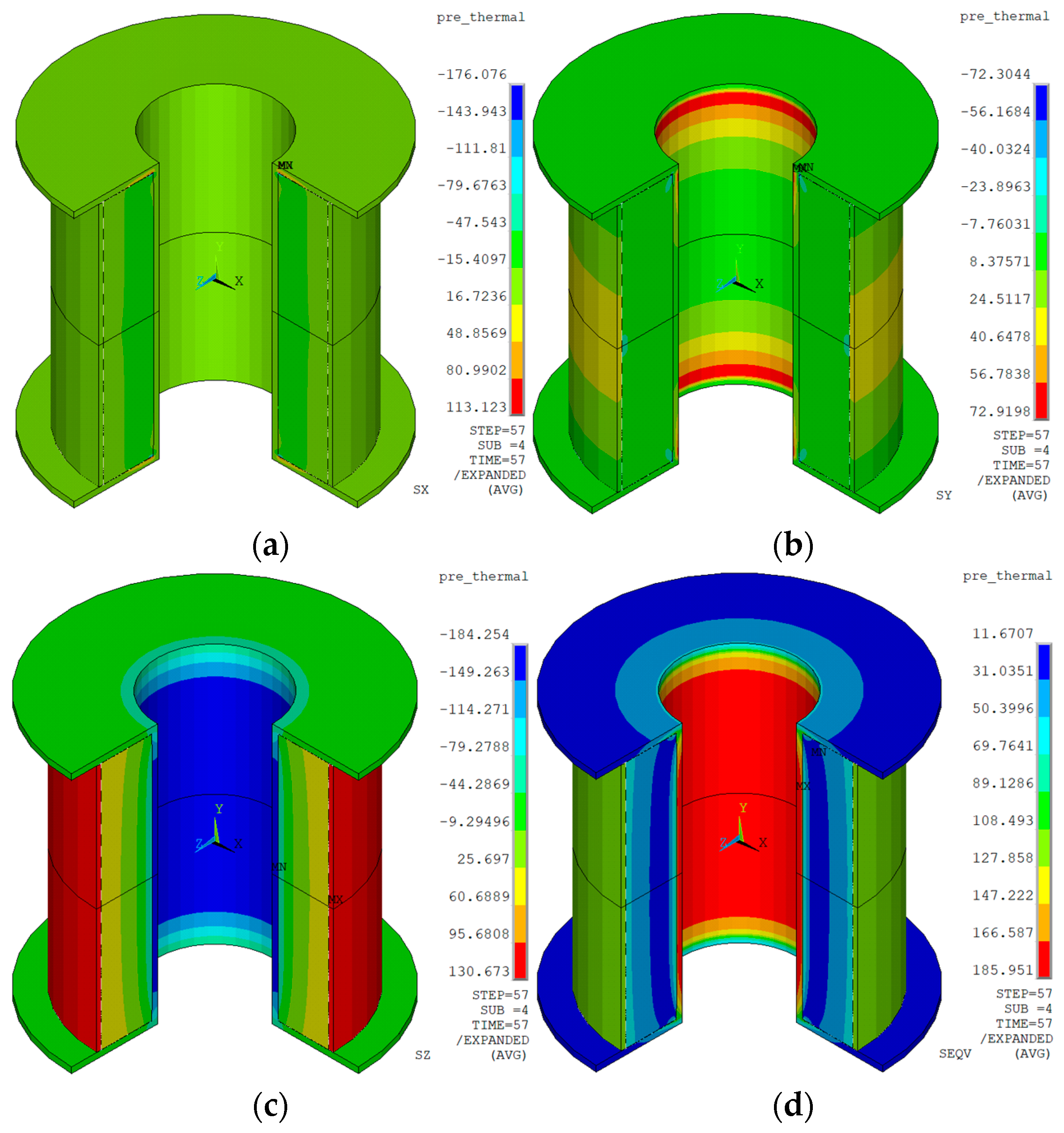
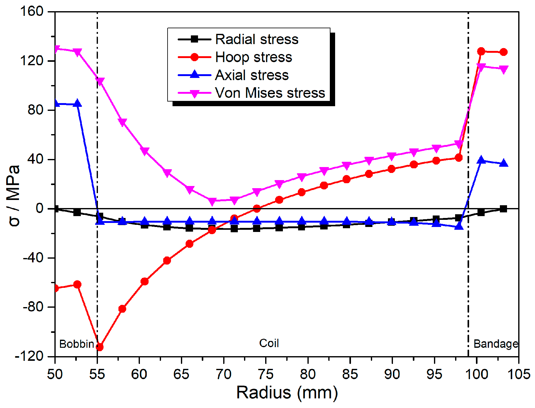
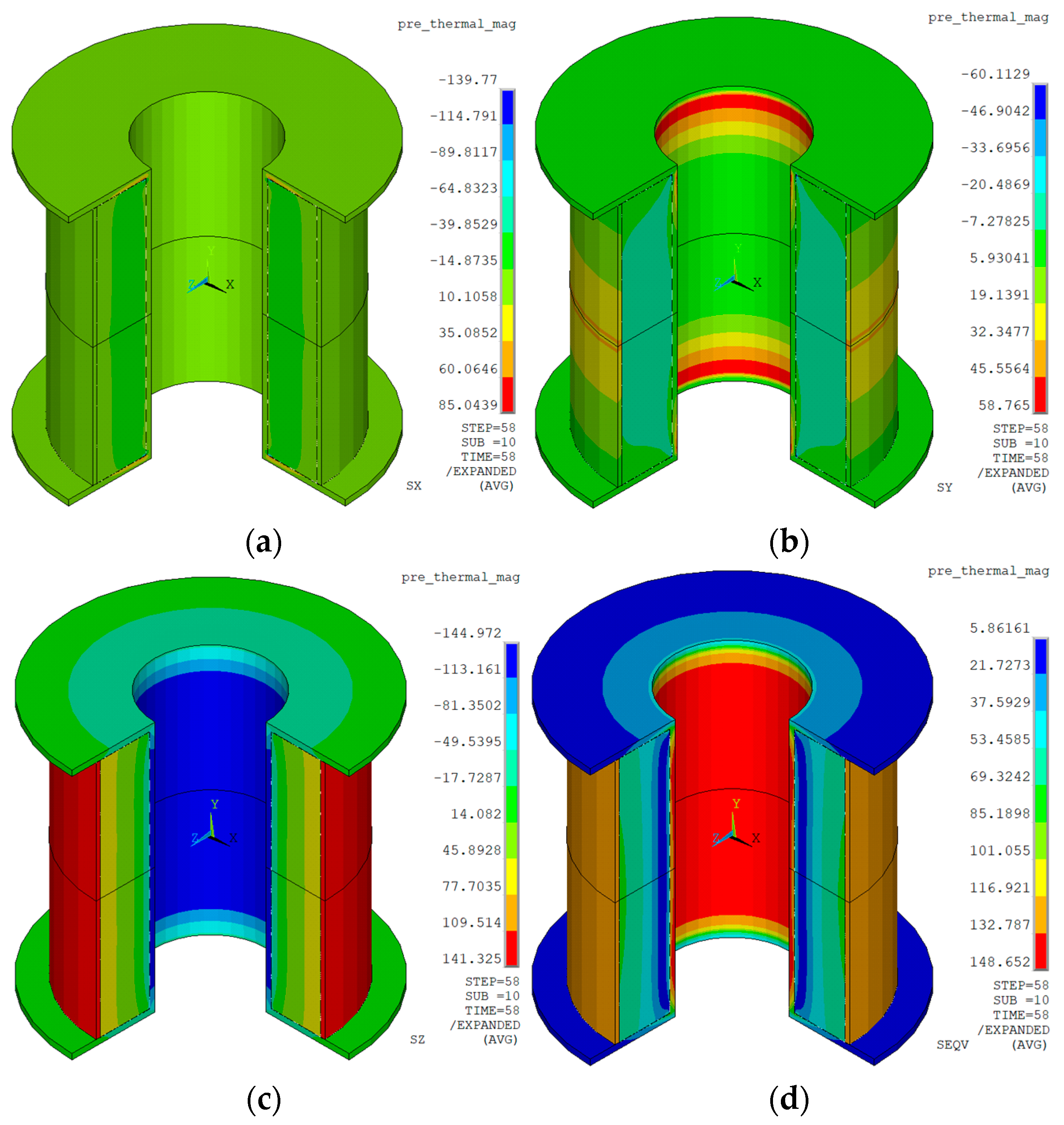
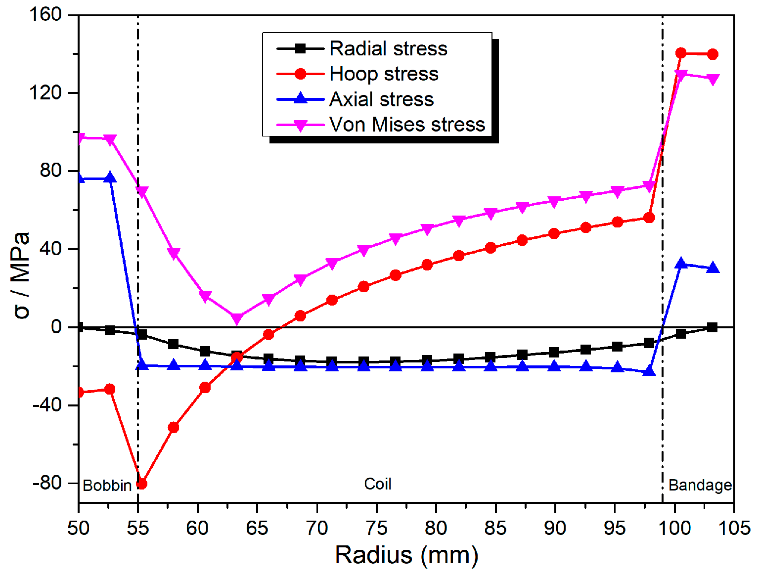
4.2. Mechanical Analysis during the Whole Processes

The 2-D axisymmetric structural element (PLANE 42) with two degrees of freedom (Ux and Uy) was used for the coil model. Due to the symmetry and equilibrium, the constraint condition of the magnet structure is that the displacement in the Y direction along the radial direction was limited to zero [33]. The stress distribution contour in the whole magnet structure after winding is shown in Figure 5.
Figure 6 shows the pre-stress distribution in the mid-plane of the magnet structure. The axial stress is neglected in Figure 6 as the coils have no axial force during the winding process. The maximum stresses of bobbin, coil, and bandage are located at the inner surface of bobbin, the innermost layer of coil, and the outermost layer of bandage. The peak von Mises stresses were about 150 MPa, 87 MPa and 60 MPa, respectively. The radial compressive stress between coil and bobbin was about −13.5 MPa. Because the coil in the inner layers is pressed by layers outside them, the hoop stress of the coil in the inner layers is negative and the maximum hoop compressive stress was −93 MPa. The maximum hoop stress of coil was 55 MPa, which occurred at the outermost layer. The hoop stress on the outermost layer of the bandage is equal to pre-stress of 60 MPa.
Figure 7 shows the stress distribution contour in the whole magnet structure after cooling down.
The stress distribution in the mid-plane of the magnet structure after cooling down is shown in Figure 8. The peak von Mises stresses on the bobbin, coil, and bandage were about 130 MPa, 103 MPa, and 114 MPa, respectively. Owing to the differences of thermal contraction coefficient among various components of coil assembly, the axial stress is generated among the bandage, coil, and bobbin. The axial stress in the coil was about −10 MPa. Because the thermal shrinkage of the coil is smaller than the bobbin, the radial compressive stress in the coil inner surface decreased to −6.3 MPa. The hoop stress on the innermost and outermost surfaces of the coil reduced to −112 MPa and 45 MPa, respectively. The maximum hoop stress in the bandage increased to 127 MPa. The two abrupt changes of stress at the interface were caused by the discontinuity of structure among the bobbin, coil, and bandage.
The stress distribution contour in the whole magnet structure after charging to the full current of 150 A is shown in Figure 9.
Figure 10 indicates the stress distribution in the coil assembly after charging to the full current of 150 A. The peak von Mises stresses in the bobbin, coil, and bandage were about 97 MPa, 70 MPa, and 128 MPa, respectively. The axial Lorentz force tried to compress the coil along axial direction, which resulted in the axial stress decreasing to its minimum of −20 MPa. The radial Lorentz force tried to split the coil from the bobbin, therefore the radial compressive stress between bobbin and coil increased to −3.5 MPa. The peak hoop stress in the coil increased to its maximum 60 MPa, which is sufficiently below the yield strength of NbTi composites of 350 MPa [41]. The maximum hoop stress in the bandage increased to 140 MPa.
The mechanical analysis results indicate that the coil always maintains compressive contact with the bobbin during the whole loading process, which can ensure good thermal conductance between the coil and bobbin. Furthermore, maximum von Mises stresses of all magnet components were far below their allowable stresses, which can validate the mechanical stability of the superconducting magnet.

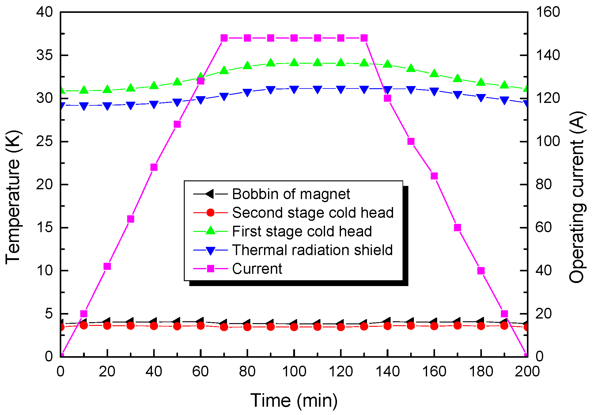
5. Operating Stability of the Superconducting Magnet

A ramping rate of 0.03 A/s was used in the charging process of the superconducting magnet, so that the AC losses of the magnet can be restricted when energizing to the target operating current of 150 A. Figure 11 shows the current and the temperature variations profile during the whole operating process.
It took about 70 min for the magnet to increase the current to 150 A. After stable operation at 150 A for about 60 min, the magnet was set to discharge, and the current discharging rate was also set to 0.03 A/s. The whole testing period lasted about 200 min. During the whole process, the temperature changes of various parts of the magnet system were quite stable. The temperature variations of the second-stage cold head and the magnet were less than 1 K, which indicates the coil structure has great thermal stability. Owing to joule heat of the first stage of current leads, the temperature of radiation shield changes from 29.18 K to 31.13 K. The operating stability test of the superconducting magnet shows that the superconducting magnet can be energized to its target current of 150 A without quenching and maintain stable operation in the charging and discharging process.

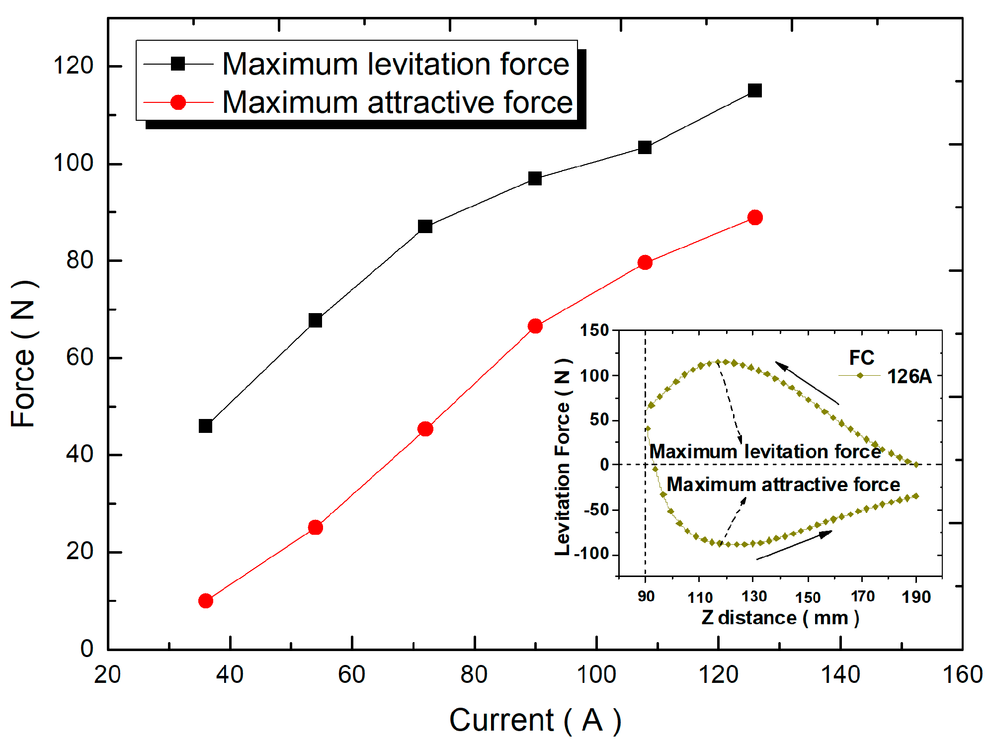
6. Levitation Force Measurement of YBCO Bulk

As shown in Figure 1b, the levitation force of YBCO bulk was measured in the bore of the superconducting magnet under liquid nitrogen (77 K). The measurement range of YBCO bulk was from the distance of z = 190 mm to 90 mm, where z is the distance from the magnet center baseline (z = 0). The exciting current of the superconducting magnet was 36, 54, 72, 90, 108, and 126 A, respectively.
Table 4 exhibits the relationship between current and magnetic field at different positions. The superconducting magnet can provide both low magnetic field and high magnetic field for the levitation force measurement of bulk as shown in Table 4. After the field cooling of the bulk at the location of z = 190 mm, the levitation force as a function of the vertical distance was measured during the vertical move from z = 190 mm to the distance of z = 90 mm, followed by a vertical move back to the initial distance of z = 190 mm.
The maximum levitation force and maximum attractive force as a function of exciting current is seen in Figure 12. The inset of Figure 12 shows levitation force versus the vertical distance between the bottom of the bulk and the magnet center baseline under exciting current of 126 A. As shown in the inset, the YBCO bulk suffered from levitation force at first and then sustained attractive force during the whole descent–ascent cycle. As shown in the figure, the maximum levitation force and maximum attractive force of YBCO bulk both increased with the increase in exciting current. When the exciting currents increased from 36 to 126 A, the maximum levitation forces rose from 46 N to 115 N and the maximum attractive forces rose from 10 N to 89 N. The experiment demonstrates that the superconducting magnet can meet the requirements for the levitation force measurement of both low magnetic field and high magnetic field.

7. Conclusions

The mechanical analysis and preliminary performance testing of the 6T NbTi conduction-cooled superconducting magnet for levitation force measurement were investigated. The NbTi superconducting magnet can provide 6 T central magnetic field in a 50 mm diameter warm bore. A 1/4 two-dimensional (2D) axisymmetric model of the magnet was established to calculate the mechanical stress of the magnet structure though the process of winding, cooling down and energizing. The results indicate that the peak von Mises stress of magnet structure was within the allowable value, which validates the mechanical integrity of the superconducting magnet. The superconducting magnet system is cooled by a two-stage GM cryocooler. The operating stability test of the superconducting magnet showed that the superconducting magnet can be charged with a ramping rate of 0.03 A/s to the maximum operating current of 150 A without quenching and work stably during the whole processes. In the levitation force measurement, the YBCO bulk suffered from levitation force at first and then sustained attractive force during the whole descent–ascent cycle. The maximum levitation force and maximum attractive force of YBCO bulk both increased with the increase in exciting current. When the exciting currents increased from 36 to 126 A, the maximum levitation forces rose from 46 N to 115 N and the maximum attractive forces rose from 10 N to 89 N. The experiments demonstrate that the superconducting magnet can not only provide a stable external magnetic field for levitation force measurement of HTS bulk without quenching, but also meet the requirements for levitation force measurement of both low magnetic field and high magnetic field.

Author Contributions

Conceptualization, L.L. and W.C.; Methodology, L.L., G.Z. and J.J.; Validation, W.C.; Formal analysis, F.C. and G.W.; Investigation, L.L.; Resources, X.Y. and Y.Z.; Writing—original draft, L.L.; Writing—review & editing, W.C.; Visualization, L.L.; Supervision, H.Z.; Project administration, F.C.; Funding acquisition, W.C. All authors have read and agreed to the published version of the manuscript.

Funding

This work was supported by the Industrial Science and Technology Project of Yueqing City under Grant 2022G007.

Data Availability Statement

The data presented in this study are available on request from the corresponding author.

Conflicts of Interest

The authors declare no conflict of interest.

References

  1. Supreeth, D.K.; Bekinal, S.I.; Chandranna, S.R.; Doddamani, M. A Review of Superconducting Magnetic Bearings and Their Application. IEEE Trans. Appl. Supercond. 2022, 32, 3800215. [Google Scholar] [CrossRef]
  2. Pang, P.; Liu, W.; Wu, F.C.; Hang, Y.; Lu, Q.L.; Ren, X.C.; Jing, H.L. Influence of Rotor Eccentricity Types on the Operating Performance for a 100 KW HTS Maglev Flywheel System. IEEE Trans. Appl. Supercond. 2021, 31, 3800206. [Google Scholar] [CrossRef]
  3. Fang, S.H.; Lv, Z.T.; Chao, C. Methods of Increasing the Energy Storage Density of Superconducting Flywheel. IEEE Trans. Appl. Supercond. 2021, 31, 5700705. [Google Scholar] [CrossRef]
  4. Douma, B.C.; Abderezzak, B.; Ailam, E.; Felseghi, R.-A.; Filote, C.; Dumitrescu, C.; Raboaca, M.S. Design Development and Analysis of a Partially Superconducting Axial Flux Motor Using YBCO Bulks. Materials 2021, 14, 4295. [Google Scholar] [CrossRef] [PubMed]
  5. Arsénio Costa, A.J.; Fernandes, J.F.P.; Melicio, R.; Cardeira, C.; Costa Branco, P.J. Numerical and Experimental Analysis of the ZFC Heat Release from a YBCO Bulk and Validation of YBCO Thermal Parameters. Crystals 2023, 13, 532. [Google Scholar] [CrossRef]
  6. Zhang, Y.; Lou, Z.; Zhang, P.; Li, C.; Zhang, J.; Zhang, X. Flux Pinning Properties of Single-Grain Bulk GdBCO Superconductors Processed by Different Thicknesses of Y123 Liquid Source. Micromachines 2022, 13, 701. [Google Scholar] [CrossRef]
  7. Ivan, I.; Ionescu, A.M.; Crisan, D.N.; Andrei, A.; Galluzzi, A.; Polichetti, M.; Mosqueira, J.; Crisan, A. Pinning Potential of the Self-Assembled Artificial Pinning Centers in Nanostructured YBa2Cu3O7−x Superconducting Films. Nanomaterials 2022, 12, 1713. [Google Scholar] [CrossRef]
  8. Zhang, H.Y.; Yang, T.H.; Li, W.X.; Xin, Y.; Li, C.; Iacchetti, M.F.; Smith, A.C.; Mueller, M. Origin of theanomalous electromechanical interaction between a moving magnetic dipole and a closed superconducting loop. Supercond. Sci. Technol. 2022, 35, 045009. [Google Scholar] [CrossRef]
  9. Bernstein, P.; Colson, L.; Noudem, J. New Magnetic Levitation System with an Increased Levitation Force. IEEE Trans. Appl. Supercond. 2019, 29, 3602204. [Google Scholar] [CrossRef]
  10. Zhao, B.J.; Deng, Z.J.; Hu, Z.X.; Liu, Y.; Zhang, S.; Zheng, Z. Levitation Force Characteristics of High-Temperature Superconducting Bulks in a High Magnetic Field. IEEE Trans. Appl. Supercond. 2020, 30, 6800305. [Google Scholar] [CrossRef]
  11. Jiang, J.; Zhao, Y.; Li, Y.H.; Zhao, L.F.; Zhang, Y. Trapped Field and Levitation Performance of a YBCO Superconductor Magnetized in Different External Magnetic Fields. J. Supercond. Nov. Magn. 2018, 32, 1885–1890. [Google Scholar] [CrossRef]
  12. Jiang, J.; Li, Y.H.; Wang, J.; Zhao, L.F.; Zhang, Y.; Zhao, Y. Levitation forces and relaxation properties of a high-Tc superconductor in varying external magnetic fields. Physica C 2020, 568, 1353582. [Google Scholar] [CrossRef]
  13. Li, L.K.; Ni, Z.P.; Cheng, J.S.; Wang, H.H.; Wang, Q.L.; Zhao, B.Z. Effect of Pretension, Support Condition, and Cool Down on Mechanical Disturbance of Superconducting Coils. IEEE Trans. Appl. Supercond. 2012, 22, 3800104. [Google Scholar]
  14. Troitino, J.F.; Bajas, H.; Bianchi, L.; Castaldo, B.; Ferracin, P.; Guinchard, M.; Izquierdo, S.; Lorenzo, J.V.; Mangiarotti, F.; Perez, J.C. A methodology for the analysis of the three-dimensional mechanical behavior of a Nb3Sn superconducting accelerator magnet during a quench. Supercond. Sci. Technol. 2021, 34, 084003. [Google Scholar] [CrossRef]
  15. Zhu, S.H.; Tan, Y.F.; Zhu, X.L.; Guo, Y.C.; Liang, T.J. Stress Analysis of 13 T Split Superconducting Magnet for Neutron Scattering. IEEE Trans. Appl. Supercond. 2021, 31, 4300705. [Google Scholar] [CrossRef]
  16. Guan, M.Z.; Hu, Q.; Gao, P.F.; Wang, X.Z.; Yang, T.J.; Wu, W.; Xin, C.J.; Wu, B.M.; Ma, L.Z. Mechanical Analysis and Measurements of a Multicomponent NbTi/Cu Superconducting Magnets Structure for the Fully Superconducting Electron Cyclotron Resonance Ion Source. Chin. Phys. Lett. 2016, 33, 058502. [Google Scholar] [CrossRef]
  17. Pes, C.; Berriaud, C.; Fazilleau, P.; Hervieu, B.; Pfister, R.; Pissart, M.; Pugnat, P. Two-Dimensional and Three-Dimensional Mechanical Analyses of the Superconducting Outsert of the LNCMI Hybrid Magnet. IEEE Trans. Appl. Supercond. 2016, 26, 4301505. [Google Scholar] [CrossRef]
  18. Li, L.K.; Cheng, J.S.; Cui, C.Y.; Li, Y.; Dai, Y.M.; Hu, X.N.; Liu, J.H.; Wang, L.; Wang, Q.L. Numerical Analysis of Mechanical Behavior for a 9.4-T Whole-Body MRI Magnet. IEEE Trans. Appl. Supercond. 2017, 27, 400505. [Google Scholar] [CrossRef]
  19. Caldwell, J. The stress in the windings of a coil carrying an electric current. J. Phys. D Appl. Phys. 1980, 13, 1379–1382. [Google Scholar] [CrossRef]
  20. Maciejewski, M.; Bayrasy, P.; Wolf, K.; Wilczek, M.; Auchmann, B.; Griesemer, T.; Bortot, T.; Prioli, M.; Navarro, A.M.F.; Schöps, S.; et al. Coupling of Magnetothermal and Mechanical Superconducting Magnet Models by Means of Mesh-Based Interpolation. IEEE Trans. Appl. Supercond. 2018, 28, 4900905. [Google Scholar] [CrossRef]
  21. Thekkethil, S.R.; Rastogi, V.; Kar, S. Multiphysics Stress Analysis of a 1.5 T Superconducting MRI Magnet. J Supercond. Nov. Magn. 2023, 36, 467–476. [Google Scholar] [CrossRef]
  22. Amin, A.A.; Baig, T.N.; Deissler, R.J.; Sabri, L.A.; Doll, D.; Tomsic, M.; Akkus, O.; Martens, M.A. Mechanical analysis of MgB2 based full body MRI coils under different winding conditions. IEEE Trans. Appl. Supercond. 2017, 27, 4602205. [Google Scholar] [CrossRef]
  23. Troitino, J.F.; Fleiter, J.; Ambrosio, G.; Bermudez, S.I.; Bajas, H.G.; Bordini, B.; Ferracin, P.; Gomez, J.V.L.; Perez, J.C.; Vallone, G.; et al. 3-D Thermal-Electric Finite Element Model of a Nb3Sn Coil During a Quench. IEEE Trans. Appl. Supercond. 2019, 29, 4701306. [Google Scholar] [CrossRef]
  24. Sackett, J.S. Calculation of electromagnetic fields and forces in coil systems of arbitrary geometry. In Proceedings of the Sixth Symposium on Engineering Problems of Fusion Research, San Diego, CA, USA, 17 November 1975. 7p. [Google Scholar]
  25. Feng, Z.K.; Li, L.K.; Gao, C.J.; Zhu, G.; Li, Y.; Li, X.; Dai, Y.M.; Wang, Q.L. The application of accurate calculation of magnetic field intensity in 1.5-T superconducting MRI magnet design. IEEE Trans. Appl. Supercond. 2012, 22, 4402206. [Google Scholar] [CrossRef]
  26. Zhang, Y.; Li, C.; Lou, Z.; Zhang, P.; Zhang, Y.; Shen, S.; Ruan, G.; Zhang, J. The Performance of the Two-Seeded GdBCO Superconductor Bulk with the Buffer by the Modified TSMG Method. Micromachines 2023, 14, 987. [Google Scholar] [CrossRef] [PubMed]
  27. Ren, Y.; Wang, F.; Chen, Z.; Chen, W. Mechanical Stability of Superconducting Magnet with Epoxy-Impregnated. IEEE Trans. Appl. Supercond. 2010, 23, 1589–1593. [Google Scholar] [CrossRef]
  28. Hu, Q.; Wang, X.Z.; Guan, M.Z.; Zhou, Y.H. Magneto-Mechanical Coupling Analysis of a Superconducting Solenoid Using FEM with Different Approaches. IEEE Trans. Appl. Supercond. 2020, 20, 4900305. [Google Scholar] [CrossRef]
  29. Kosse, J.J.; Wessel, W.A.J.; Zhou, C.; Dhalle, M.; Tomas, G.; Krooshoop, H.J.G.; ter Brake, H.J.M.; ten Kate, H.H.J. Mechanical design of a superconducting demonstrator for magnetic density separation. Supercond. Sci. Technol. 2021, 34, 115019. [Google Scholar] [CrossRef]
  30. Chen, J.B.; Jiang, X.H. Stress Analysis of a 7 T Actively Shielded Superconducting Magnet for Animal MRI. IEEE Trans. Appl. Supercond. 2012, 22, 4903104. [Google Scholar] [CrossRef]
  31. Iwasa, Y. Case Studies in Superconducting Magnets-Design and Operational Issues; Plenum Press: New York, NY, USA, 2009; pp. 638–646. [Google Scholar]
  32. Marquardt, E. Cryogenic Material Properties Database. In Cryocoolers; Springer: Boston, MA, USA, 2002; pp. 681–687. [Google Scholar]
  33. Chen, P.; Dai, Y.M.; Wang, Q.L.; Zhang, Q. Mechanical Behavior Analysis of a 1 MJ SMES Magnet. IEEE Trans. Appl. Supercond. 2010, 20, 1916–1919. [Google Scholar] [CrossRef]
  34. Amin, A.A.; Sabri, L.; Poole, C.; Baig, T.; Deissler, R.J.; Rindfleisch, M.; Doll, D.; Tomsic, M.; Akkus, O.; Martens, M. Computational homogenization of the elastic and thermal properties of superconducting composite MgB2 wire. Compos. Struct. 2018, 188, 313–329. [Google Scholar] [CrossRef]
  35. Wang, L.; Wang, Q.L.; Li, L.K.; Qin, L.; Liu, J.H.; Li, Y.; Hu, X.N. The Effect of Winding Conditions on the Stress Distribution in a 10.7 T REBCO Insert for the 25.7 T Superconducting Magnet. IEEE Trans. Appl. Supercond. 2018, 28, 4600805. [Google Scholar] [CrossRef]
  36. Gao, P.F.; Wei, X.P.; Wu, B.M.; Xin, C.J.; Liao, T.F.; Wu, W.; Guan, M.Z. Numerical investigation on decreasing radial stress in epoxy impregnated REBCO pancake coils by overband. Cryogenics 2019, 103, 102971. [Google Scholar] [CrossRef]
  37. Niu, M.D.; Xia, J.; Yong, H.D.; Zhou, Y.H. Quench characteristics and mechanical responses during quench propagation in rare earth barium copper oxide pancake coils. Appl. Math. Mech. 2021, 42, 235–250. [Google Scholar] [CrossRef]
  38. Zhou, W.H.; Zhou, Y.H. Electric-magnetic-force characteristics of rare earth barium copper oxide superconductor high-fleld coils based on screening efiect and strain sensitivity. Appl. Math. Mech. 2022, 43, 1249–1268. [Google Scholar] [CrossRef]
  39. Kang, X.; Tong, Y.J.; Wu, W.; Wang, X.Z. Transient multi-physics behavior of an insert high temperature superconducting no-insulation coil in hybrid superconducting magnets with inductive coupling. Appl. Math. Mech. 2023, 44, 255–272. [Google Scholar] [CrossRef]
  40. Liu, D.H.; Li, D.K.; Zhang, W.W.; Yong, H.D.; Zhou, Y.H. Electromagnetic-thermal-mechanical characteristics with active feedback control in a high-temperature superconducting no insulation magnet. Sci. China Phys. Mech. 2022, 65, 294612. [Google Scholar] [CrossRef]
  41. Ning, F.P.; Wang, M.F.; Yang, H.; Zhang, G.Q.; Ma, W.B.; Liu, Z.Y.; Du, X.J.; Yao, W.Z.; Zhu, Z.X. Physical Design of High Gradient Superconducting Magnetic Separation Magnet for Kaolin. IEEE Trans. Appl. Supercond. 2012, 22, 3700104. [Google Scholar] [CrossRef]
Figure 1. Levitation force measurement system: (a) actual structure; (b) schematic illustration.
Crystals 13 01117 g001
Figure 2. (a) Structural model of the magnet; (b) 1/4 two-dimensional axisymmetric mesh model of the superconducting magnet; (c) three-dimensional expanded mesh model from 1/4 two-dimensional axisymmetric model.
Crystals 13 01117 g002
Figure 3. Magnetic field distribution for superconducting magnet.
Crystals 13 01117 g003
Figure 4. Magnetic field and electromagnetic force as a function of radius in the coil mid-plane.
Crystals 13 01117 g004
Figure 5. Stress distribution contour in the whole magnet structure after winding: (a) axial stress; (b) radial stress; (c) hoop stress; (d) von Mises stress.
Crystals 13 01117 g005
Figure 6. Stress distribution in the mid−plane of the magnet after winding.
Crystals 13 01117 g006
Figure 7. Stress distribution contour in the whole magnet structure after cooling down: (a) axial stress; (b) radial stress; (c) hoop stress; (d) von Mises stress.
Crystals 13 01117 g007
Figure 8. Stress distribution in the mid−plane of the magnet after cooling down.
Crystals 13 01117 g008
Figure 9. Stress distribution contour in the whole magnet structure after charging: (a) axial stress; (b) radial stress; (c) hoop stress; (d) von Mises stress.
Crystals 13 01117 g009
Figure 10. Stress distribution in the mid−plane of the magnet after charging.
Crystals 13 01117 g010
Figure 11. Temperature changes with respect to time during the whole operating processes.
Crystals 13 01117 g011
Figure 12. Levitation force versus different current range from 36 to 126 A.
Crystals 13 01117 g012
Table 1. Main parameters of superconducting coil.
ItemsParameters
Superconducting wireNbTi/Cu
Wire sectional dimension length × width (mm)1.2 × 0.75
Inner diameter (mm)110
Outer diameter (mm)198.4
Height (mm)216.15
Coil turns per layer165
Coil layers52
Maximum magnetic field (T)6.23
Operating current (A)150
Table 2. Material properties of different parts of the structure.
MaterialElastic Modulus
E(GPa)
Poisson’s Ratio
ν
Thermal Contraction
( Δ L / L ) 300 4.2 K
300 K4.2 K300 K4.2 K
NbTi alloy80820.30.30.194%
Epoxy resin480.330.330.433%
Cu1301400.330.330.295%
Al70800.320.320.413%
Table 3. Equivalent material properties of the coil.
Equivalent Material Properties300 K4.2 KThermal Contraction
( Δ L / L ) 300 4.2 K
Ex (GPa)26.543.7αxΔT = 0.418%
Ey (GPa)39.844.2αyΔT = 0.357%
Ez (GPa)93.2100.3αzΔT = 0.313%
Gxy (GPa)9.615.4
Gyz (GPa)32.736.8
Gzx (GPa)26.330.2
νxy0.3230.326
νyz0.2340.246
νzx0.2180.225
Table 4. The relationship between current and magnetic field at different positions.
Current (A)Bz (T)
Z = 190 mmZ = 90 mm
360.21.03
540.31.55
720.42.08
900.512.56
1080.63.13
1260.73.65
Disclaimer/Publisher’s Note: The statements, opinions and data contained in all publications are solely those of the individual author(s) and contributor(s) and not of MDPI and/or the editor(s). MDPI and/or the editor(s) disclaim responsibility for any injury to people or property resulting from any ideas, methods, instructions or products referred to in the content.

