Article

Towards Closed-Loop Recycling of Ceramic Particle-Reinforced Aluminium Alloys: Comparative Study of Resistance-Heating Sintered Primary and Solid-State Recycled Secondary SiCp/AlSi7Mg Composites

Materials and Surface Engineering Group, Institute of Materials Science and Engineering, Chemnitz University of Technology, Erfenschlager Str. 73, 09125 Chemnitz, Germany
*
Author to whom correspondence should be addressed.
Crystals 2023, 13(5), 830; https://doi.org/10.3390/cryst13050830
Submission received: 28 April 2023 / Revised: 12 May 2023 / Accepted: 15 May 2023 / Published: 17 May 2023
(This article belongs to the Special Issue Current Status and Recent Progress on Advanced Aluminum Alloys)

Abstract

:
Particle-reinforced aluminium matrix composites (AMC) with a high-volume fraction of ceramic reinforcement (>30 vol.%) combine high specific strength and stiffness with good wear resistance and thermal stability, resulting in their increasing popularity in high-load applications, such as brake discs and bearings. It is hence assumed that AMC will accumulate as scrap in the near future. Appropriate recycling strategies must therefore be developed to maintain AMC’s inherent properties. Melt-metallurgical recycling routes bear the danger of dissolving the ceramic reinforcement in the liquid metallic matrix and contaminating primary melts or forming intermetallic phases in secondary melts. Here, a solid-state AMC recycling route with crushing and sintering is investigated, wherein all steps are carried out below the solidification temperature of the aluminium matrix. A sintered primary AMC is mechanically converted into a particulate/powdery secondary raw AMC in coarse, medium, and milled quality (i.e., with d ≈ 7–12 mm, d ≈ 3–7 mm, and d < 300 µm) and subsequently resistance heating sintered to a secondary AMC under a variation of the sintering pressure. The two AMC generations are analysed and discussed regarding their microstructure and mechanical properties. Since the secondary AMC show reduced the mechanical strength, the fracture surfaces are analysed, revealing iron contaminations from the mechanical processing.

1. Introduction

Since the mechanical strength and wear resistance of aluminium matrix composites (AMC) increase with increasing volume fraction of ceramic particle reinforcement [1], the market share of high-particle-reinforced AMC increases likewise. This trend already exists especially due to the beginning commercialisation of AMC brake discs, although mass production processes are currently lacking. Despite the nearly wear-free behaviour of high-particle-reinforced AMC in tribological contact with semi-metallic brake lining material [2], a significant amount of AMC scrap with a high content of ceramic hard phases is to be expected at the end of the latest car life cycle.
Due to similar characteristics of aluminium alloys and AMC (like density, colour, and non-magnetic behaviour), low amounts of AMC are likely to be recycled undetected by state-of-the-art melt metallurgy processes together with other aluminium scrap. In this way, not only does melt contamination occur due to fully or partly dissolving reinforcement particles, resulting in the formation of brittle phases (e.g., in the interface area) [3,4,5], but also the AMC itself as a high-performance composite with defined properties and a high inherent value (due to the former expenditures in production resources and energies) gets lost. A single-variety recycling route is required to maintain both AMC material properties and inherent values. Melt-metallurgical recycling routes can be applied, especially to AMC with an aluminium cast alloy matrix. However, due of the typical extended process periods and high process temperatures, the reinforcing phase may segregate or (partly) dissolve, forming unwanted reaction phases. The properties of the resulting secondary AMC, hence, are likely to vary significantly from the properties of the initial AMC. Therefore, an alternative way to retain specific properties of high-particle-reinforced AMC is needed.
AMC with high volume fraction of ceramic reinforcements, such as SiC, TiC, and Al2O3, are significantly more brittle than unreinforced aluminium alloys [6,7,8]. This specific characteristic of high-particle-reinforced AMC materials makes their mechanical recycling possible. It is to be expected that the initial microstructure of a high-particle-reinforced AMC can be maintained during a solid-state recycling process due to its low deformation capacity (toughness) [9] and brittle cracking behaviour [10]. In this study, mechanical recycling is defined as a simple crushing or milling process that is not prone to (significantly) change the local chemical composition and general properties of the recycled AMC. In this way, the selected recycling route opens up multiple AMC reuse/recycling steps to create a closed-loop material life.
The result of the so defined mechanical recycling of AMC will be a more or less broad AMC particle/powder fraction depending on the AMC composition, the chosen crushing and milling processes, and their parameters. These particle/powder fractions can then be further processed by powder-metallurgical processes. A fast and robust consolidation method is the resistance heating sintering (RHS), also known as SPS (spark plasma sintering) or FAST (field assisted sintering technique). Here, it is referred to as RHS to specifically describe sintering by resistance heating of the sintering powder, either directly through its own electrical resistance or indirectly with the used (graphite) tool. RHS is used since it is under discussion, whether spark plasmas occur during this process (which excludes the term SPS), as well as the terminology “field assisted sintering” (i.e., FAST), which includes different processes [11]. By means of RHS, the AMC particle or powder material can be consolidated within a few minutes due to high heating and cooling rates and a sintering process temperature near the solidification temperature of the AMC’s aluminium matrix, hence creating a strong diffusion flux. A further accelerated densification during RHS can be achieved by applying an additional mechanical load.
In this study, the described solid-state processes, i.e., mechanical recycling and RHS, are combined to process primary AMC material to compact irregular and mixed AMC particles and, subsequently, to a secondary AMC material. These processes were specifically selected as processes with a low impact on the initial AMC microstructure and properties. This impact will be evaluated in order to consistently pursue the idea of a later closed-loop solid-state recycling route.

2. Materials and Methods

2.1. Material and Preparation

An AMC with an AlSi7Mg matrix alloy and 35 vol.% silicon carbide particles (SiCp, F400) was consolidated by RHS. Figure 1 shows the microstructure, with light grey areas representing the aluminium matrix and middle grey areas representing the ceramic particles. The dark grey to black areas are associated with process-related pores.
The bulk AMC material, a disc with a diameter of 200 mm and a height of approximately 10 mm was crushed in an undefined manner using a mechanically controlled press. From the resulting wide AMC particle fraction, two fractions with average diameters between ≈7 mm to 12 mm (coarse) and ≈3 mm to 7 mm (middle) were selected for further investigations. In addition, chips from mechanical machining of the same material were milled using Al2O3 balls (with diameters of 20 mm) in a laboratory scaled planet ball miller (Pulverisette 5, Fritsch GmbH, Idar-Oberstein, Germany). Both drums and balls used during milling were made of zirconium oxide and aluminium oxide, respectively, showing a significantly higher hardness than AMC milling good (approx. 100 HBW 62.5/2.5) and, thus, preventing abrasion and contamination of the recycled AMC material. Ball-milling was carried out for 30 min at 100 rpm, followed by three runs with a duration of 5 min at 200 rpm with intermittent cooling for 5 min to avoid significant temperature increase. The resulting powder consisted of fine particles (<300 µm) of irregular shape. The three AMC fractions “coarse”, “middle”, and “filler” (milled chips) are described in detail in Table 1.
Since the bulk density has a noticeable influence on the subsequent sintering result, it was measured for all fractions, as described in [9]. For calculation of the relative density, the measured values were put into ratio with the density of 2.86 g/cm3 corresponding to an ideal AMC body of this specific composition. The results are shown in Table 2.
In order to increase the bulk density, mixed fractions of either coarse or middle fraction together with the filler fraction were used. The theoretically optimal mixing ratios are approx.: 1:1 mass mixture ratio (AMC particles to AMC chips) for the coarse mixed (CM) and a 2:1 mass mixture ratio for the middle mixed fraction (MM). The CM and MM fractions were then used for further processing by RHS in order to evaluate the recyclability of the initial AMC material.

2.2. Consolidation and Sample Preparation

2.2.1. Resistance Heating Sintering (RHS)

The above-mentioned recycling fractions were separately filled in a graphite tool with an inner diameter of 30 mm and consolidated by RHS with a SPS KCE FCT-HP D 25-SI device (FCT Systeme GmbH, Frankenblick, Germany). Similar RHS routes were applied to process the CM and MM fractions. First, the vacuum chamber was evacuated twice with argon gas flooding in-between. After setting a vacuum of 1 mbar, the sintering pressure was raised to 50 MPa for the CM fraction and to 30 MPa for the MM fraction. The sintering processes’ heating rates were 100 K/min until equal sintering temperatures of 520 °C were reached, controlled by pyrometer measuring from 5 mm distance within a borehole in the graphite tool right above the samples’ centre surfaces. The sintering temperature was held for 10 min. Afterwards, the graphite tool containing the sintered recycling parts was cooled down uncontrolled by the water-cooled press punches of the device. To prevent adhesion between the sintered parts and the rough surface of the graphite tool, graphite interlayers were used during the whole sintering process.

2.2.2. Sampling

The following samples were cut by wire eroding from each sintering sample:
  • Four cross sectional parts for microstructural analysis;
  • Three miniature bone shaped tensile specimens;
  • Three cylindrical compression specimens.
The sample positions within the produced sinter parts are schematically illustrated in Figure 2. As constant heating across the entire sample cannot be guaranteed by the used RHS setup, the outer compression specimens were marked extra and the tensile specimens were located as near to the sinter part’s centre as possible.
The metallographic sections were prepared with a usual preparation routine of grinding and polishing.

2.3. Mechanical Testing

2.3.1. Compression Test

The compression tests were carried out in a ZwickRoell Z100 universal testing machine (ZwickRoell GmbH & Co., KG, Ulm, Germany). The set strain rate was 10−3 s−1 (quasi static), and the contact surfaces of the specimens were covered with molybdenum disulphide to avoid additional friction during testing and to ensure a nearly uniaxial compression. All specimens, i.e., three for each recycling condition (CM and MM), were compressed to 50% of their initial height. The yield strength and the strength at a compression of 20% were evaluated.

2.3.2. Tensile Test

For the evaluation of the behaviour under tensile load, the miniature bone shaped specimens (see Figure 2) were tested in a ZwickRoell Z020 universal testing machine (ZwickRoell GmbH & Co., KG, Ulm, Germany) under quasi static condition (10−3 s−1). Strain was measured with digital image correlation (Carl Zeiss GOM Metrology GmbH, Braunschweig, Germany). The strains along the direction of tensile load were monitored to evaluate local deformation. Images for further discussion were taken at the moment of first appearances of local deformations and instantly before failure in order to be able to conclude on weak points or areas in the recycled sinter bodies.

2.4. Microstructural Analysis

2.4.1. Qualitative and Quantitative Microstructural Analysis

The investigation of the cross-sectional areas at different magnifications were carried out with an optical microscope Olympus GX51 (Olympus Deutschland GmbH, Hamburg, Germany) for qualitative evaluation. The porosity was quantified using the software Stream Motion 2.1 (Olympus Deutschland GmbH, Evident Corporation, Tokyo, Japan; evaluation software: Olympus Stream Motion 2.1) via grey threshold values by using 10 ranges of interest of (800 × 800) µm2 to obtain an average porosity value for each type of secondary AMC.
For a better understanding of the fracture behaviour, selected tensile specimens were prepared for microstructural analysis. The fracture surfaces, as well as the flat side of the tensile specimens that was already monitored during tensile tests with digital image correlation, were examined using stereo microscopy, scanning electron microscopy (SEM; ZEISS LEO 1455VP, Carl Zeiss Microscopy Deutschland GmbH, Oberkochen, Germany), and EDX (energy dispersive X-ray spectroscopy).

2.4.2. Interface Indentation

The bonding of the former (powder) particles play a major role for the properties of the sintered material. The interface quality between particles of the coarse and middle particle fraction of the crushed AMC and the milled filler powder especially must be described by an appropriate, characteristic value to evaluate the recycling result. A Fischerscope HM2000 xy instrumented indentation testing device (Helmut Fischer GmbH, Sindelfingen, Germany) equipped with Vickers indenter was used for a non-standardised interface bonding test following the interfacial indentation test of Marot et al. [12]. Therefore, ten indents were set perpendicularly along interface areas (see Figure 3) to “trigger” cracks in case the bonding in the interface is worse than within the particles themselves.

3. Results and Discussion

3.1. Microstructural Evaluation of Sintering Qualities

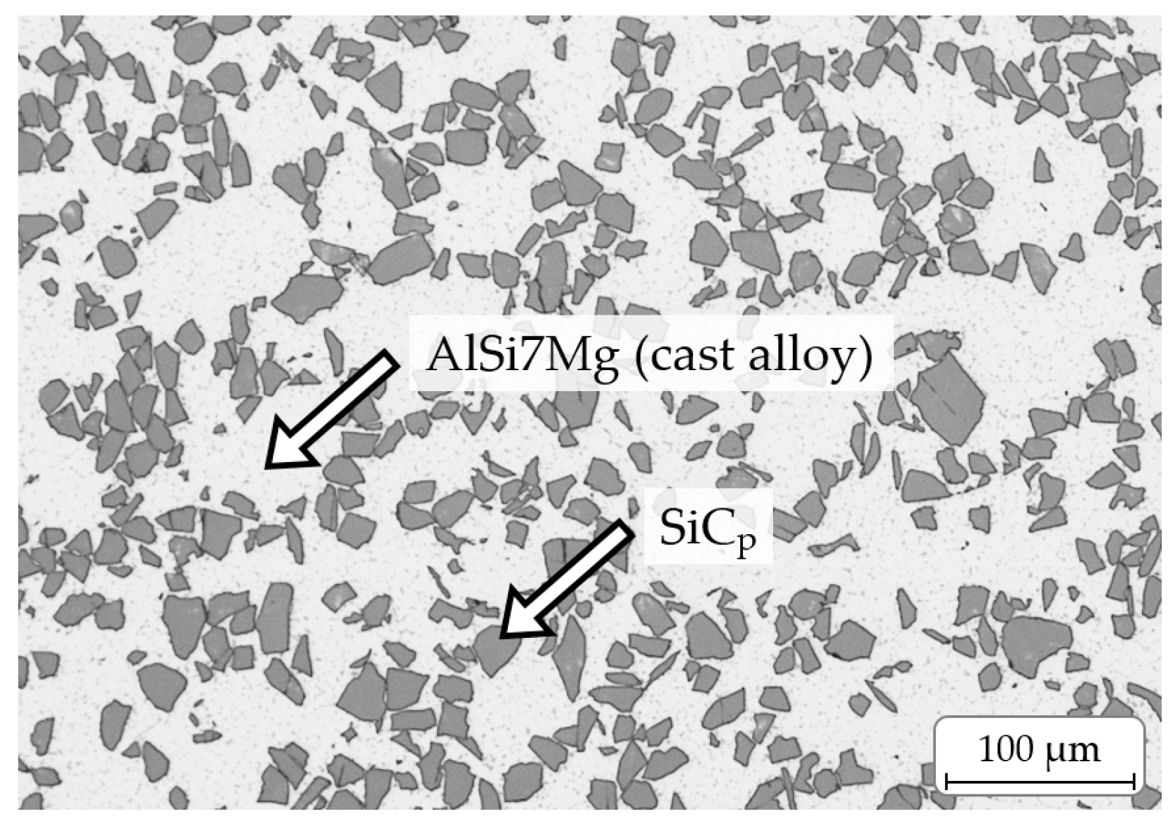
Figure 4 provides an overview of the macro- and microstructures of the sintered samples. The stereomicroscopic images in the first row clearly show areas of different appearance. On the one hand, there are large dark areas corresponding with former particles from the particulate material (see Table 1). On the other hand, there is a lighter appearing material in-between corresponding with the former filler material, i.e., milled chips (see Table 1). Its lighter appearance is obviously caused by a higher amount of smaller and more finely dispersed SiCp (see Figure 4c,d), which lead to a stronger light reflection.
The light microscopic pictures in Figure 4 show that in the former chip areas, the average SiCp particle size is significantly smaller and more heterogeneous in comparison to the reinforcement phase of the initial AMC material. This heterogeneity in size is probably the result of varying cutting forces and deformation grades during chip formation in the applied turning process. The amount of cracked SiC particles is higher in chip locations that experienced a higher mechanical load during cutting, whereas in locations with a lower local load, the SiC particles stayed intact.
Figure 4 further displays that the particles from the “coarse” and “middle” AMC particulate material are fully embedded within a matrix of the milled chips “filler” (see also Table 1). The different particle types were successfully sintered with the applied RHS route, i.e., former particle boundaries cannot (CM fraction) or can just barely (MM fraction) be seen in the light microscopic pictures in Figure 4. Only the change in mean SiC particle size, i.e., the presence of fragmented SiCp, reflects the transition from one type of starting powder/particle fraction to another. Cislo et al. [13] investigated the solid-state recycling (comminution, cleansing, pre-compaction, pulsed electric current sintering) of EN AW 6082 chips and observed a similar result. In their investigations, residue chip boundaries were also barely visible.
The details in Figure 4c–f show the differences between the two sintered secondary AMC types using either the CM or the MM fraction. The secondary AMC produced under the use of the MM condition shows a significant level of pores, mainly in the interface area between the former chip filler and medium particulate fraction and also in the region of the former chip filler, as well as in some former particles of the particulate material. This—in comparison to the AMC produced from a CM fraction high-level of porosity—is explained by the lower sintering pressure while processing the MM fraction (see Section 2.2.1). Since the relative powder density of the CM and MM fraction were similar (Table 2), the lower sintering pressure resulted in a reduced volume diffusion flux that is needed to fill the present gaps, cavities, and pores. This volume diffusion flux, on the other hand, was higher during the sintering of the CM fraction under a higher sintering pressure. As a result, while the CM exhibits a nearly pore-free microstructure, the MM has a porosity of about 0.5–1.0% over the whole cross-sectional area.
For a better evaluation of the bonding between the former AMC particulate and powder material, interface indentations were carried out in both the secondary AMC from the CM and MM fraction. Figure 5 shows typical interface areas before and after the indentation. The interface areas are respectively marked with the light dashed lines. In all cases, no visible cracks along the interfaces were triggered by the indenter. Only the area near the indentation was deformed by the volume displacement. This is also in accordance with earlier investigation results by Cislo et al. [13]. While a delamination of the former chip particles after pre-compaction at room temperature was observed, the consolidation through sintering led to a strong bond, that corresponded to the coherence in the material itself. Due to the absence of cracks in both secondary AMC, the interfacial toughness cannot be determined according to [12]. Since failure on the part of the particulate/filler material is more likely to be observed, it can be assumed that the bond between the fractions corresponds to the cohesion within the sintered fractions. These interfaces are therefore evaluated as metallurgically bonded.
Furthermore, dark and rarely occurring, the elongated phases (Figure 4g,h) were observed in the interface areas of particulate material particles. Whether at all and to what extent these phases have an influence on the fracture behaviour is described and discussed in Section 3.3.

3.2. Mechanical Behaviour under Tensile and Compressive Load

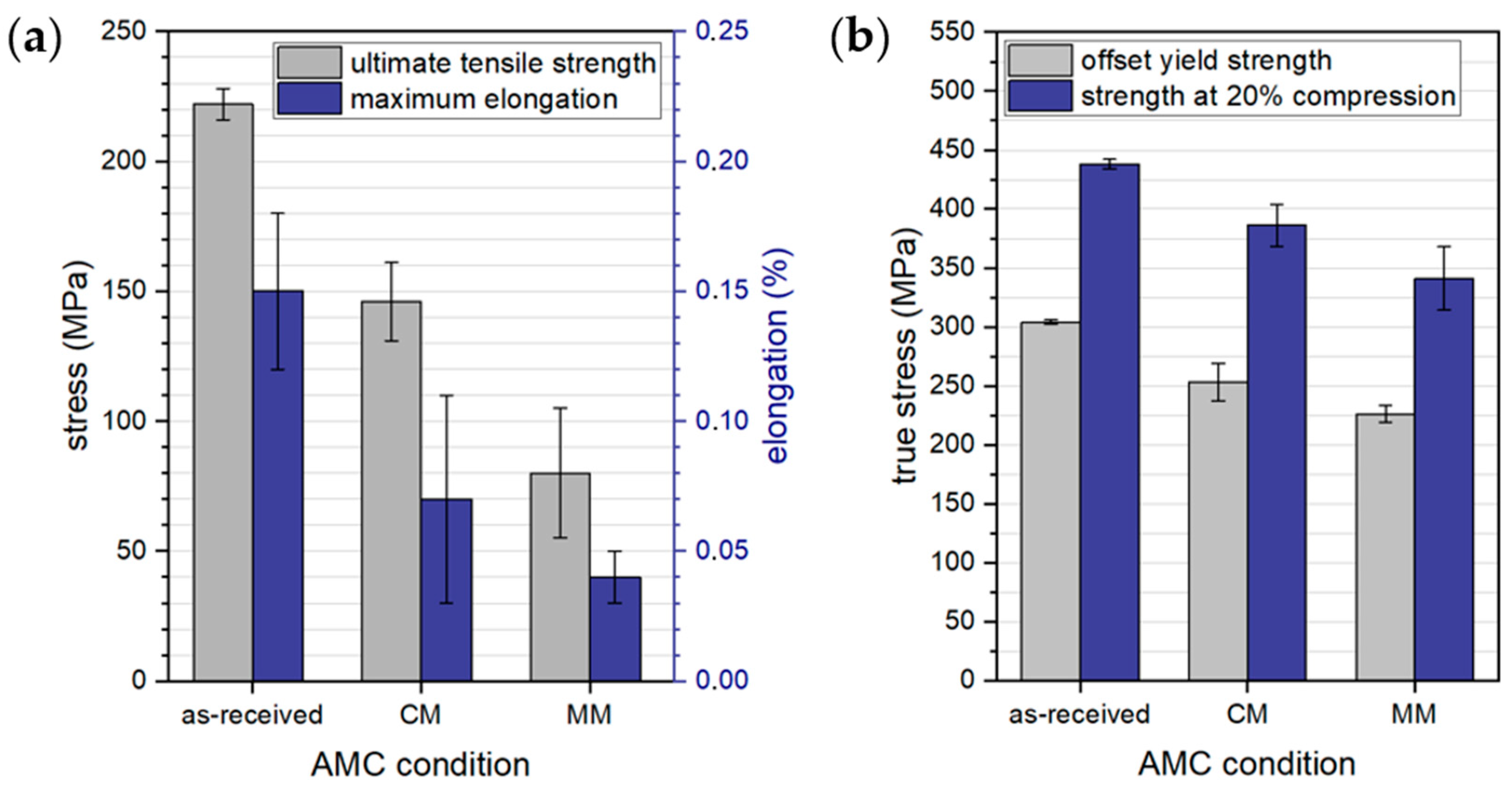
The results of the quasi-static tests under a tensile and compressive load are presented in Figure 6. Compared to the initial AMC condition (as-received), the tensile strength of the sintered AMC using a CM fraction is reduced by about 30% and that for an MM fraction by about 60%. It can be assumed that a weaker bonding between the heterogeneous areas, i.e., between the filler and coarse or medium particulate phase, respectively, leads to failure already at lower stresses since the observed small variation of the present porosity level does not strongly affect the AMC strength [9]. In general, the strength values of the recycled conditions scatter more strongly than those obtained for the initial as-received AMC. However, this originates from the more irregular AMC composition respective the described areas of former filler and particulate AMC material in combination with the small specimen volumes during mechanical testing. In addition, the average maximum strains for the recycled AMC conditions are significantly lower than the as-received condition. This indicates an extremely brittle behaviour of the recycled fractions.
The compression tests confirm that secondary AMC obtained from the CM and MM fraction exhibit lower strength than the initial as-received AMC and that the AMC from the CM fraction shows higher strength values than that from the MM fraction. In comparison to the tensile strength values, however, the grade of the strength reduction was lower in the compression tests. Simultaneously, the specimens show a significantly higher deformation capacity in the compression tests due to the absence of the notch effect of the pores. Nevertheless, in the case of the AMC obtained from the MM fraction, the observed pores reduce the effective cross-sectional area and, therefore, enable material flow at lower global stresses. Further, the lower content of the filler fraction with its fine SiC particles offers a lower dispersion hardening effect compared to the AMC obtained from the CM fraction. In comparison with the offset yield strength, the strength of all conditions at a 20% compression increased by about 50% (Figure 6b, blue bars). After reaching the yield strength (Figure 6b, grey bars), retained pores in the AMC flatten, and strain-hardening takes place. However, the absolute increase in stress due to strain hardening (and friction) is about 135 MPa for the AMC from the CM fraction and about 115 MPa for that of the MM fraction. This higher strength could result from the better bonding state in the AMC-internal interfaces between the former filler and particulate material, which is likely to be caused by the increased driving force for sintering due to the increased process pressure, discussed above [14].
In addition, in all AMC qualities, dispersion hardening could occur since the fine particles do not only work as pinning sites for dislocations, but also as effective obstacles for dislocation movement. This results in a similar relative increase in strength up to a compression of 20% for all tested AMC despite their different microstructures.
Nevertheless, the initial condition with its homogeneous AMC microstructure exhibits the highest yield strength when compared to the secondary AMC conditions. This is again attributed to the heterogeneous distribution of differently sized former AMC particles, as well as areas of significantly differing SiCp sizes in the secondary AMC obtained from the CM and MM fraction. The difference in bearable stress may specifically be attributed to the present interfaces between the former filler and particulate fractions, as well as local gradients of mechanical properties. Guo et al. [15] recycled a 15% B4C reinforced Al 1060 with melt metallurgy. They observed no reduction in mechanical properties after recycling. A better distribution of the reinforcement phase after recycling even led to a slight improvement in the mechanical properties. However, a local formation of a reaction phase during sintering was also observed. The followed recycling route is therefore limited in terms of the reinforcement content due to the already described risk of the formation of brittle detrimental phases.
An additional strength-reducing influence on the investigated secondary AMC could be reaction phases or contaminations that result from the mechanical crushing and milling of the secondary AMC raw material and that concentrate at the internal secondary AMC interfaces. Therefore, a fracture face analysis is addressed in Section 3.3.

3.3. Fracture Analysis

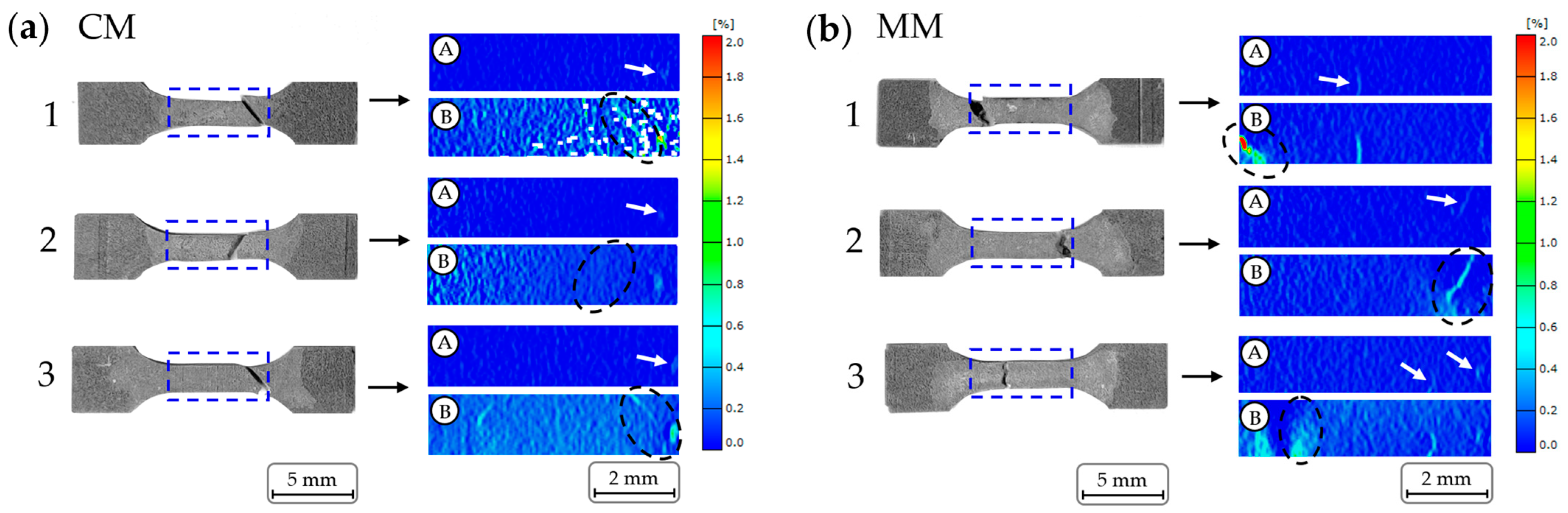
A full fracture analysis on each individual tensile specimen of the recycled AMC sinter materials was performed to reveal the influence of the heterogeneous microstructure on the fracture behaviour. In Figure 7, the recorded local deformations are presented. Dashed blue frames on the respective specimen macrographs mark the regions of interest recorded by digital image correlation.
The presented images of these records marked with an A represent the beginnings of the respective localised deformation, whereas pictures marked with a B correspond to the respective last records before failure. White arrows in these images point to the locations of the first deformation, and the black dashed ellipses encircle the regions of failure.
As can be seen by the displayed deformation scales, the local deformation in tensile stress direction did not exceed 2.0%, and the global deformation was not higher than 0.7% on average (Figure 6a). Comparing the respective images A and B, it is important to note that the locations of the first deformations do not, in most cases, correlate with those of the later sample failure. The reason for this is that only one surface of the tensile test specimens was observed while deformation localisations that led to failure could only be apparent on the specimens’ backs. Comparing the images from a digital picture analysis with the respective macrographs, differences in the fracture behaviour of AMC obtained from the CM and MM particle/powder fractions become visible. AMC specimens from the CM fractions mainly failed under a shear fracture while the AMC specimens from MM fractions showed an irregular, mixed-to-normal stress fracture.
SEM examinations were carried out to better understand the structural differences that lead to the different fracture types. Specimen number 3 (compare Figure 7) was chosen as a representative for both secondary AMC types. 
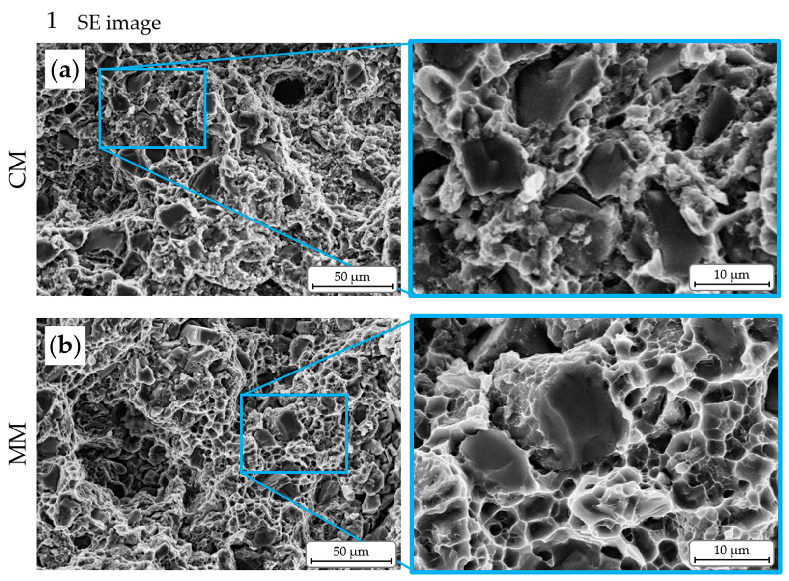
Figure 8 gives an overview of the fracture surfaces for AMC obtained from the CM (a) and MM (b) particle/powder fractions, respectively. The stereomicrographs at the tops are included for easier allocation. The respective SEM images of the tilted fracture surfaces are presented below, giving impressions on the topography (SE contrast) and element composition (BSE contrast).
It is noticeable that, in Figure 8a, about 80% of the fracture surface of the AMC obtained from the CM particle fraction are very fine and smooth while the rest is clearly more fragmented and rougher. On the other hand, the AMC obtained from the MM fraction (Figure 8b) has an inversed appearance: the largest part of the fracture surface is characterised by severe fracturing, and smooth surface areas are seldom. The smooth and angled fracture surface areas are related to areas of shear fracture, whereas the rough areas represent areas of normal stress breaking.
Besides the different roughness values and angles of these areas, differences in their elemental composition can be seen. The BSE images indicate a concentration of an element with a significantly higher atomic mass (light grey/white dots) than aluminium in the fracture surfaces of both AMC types. The concentration of this element appears to be higher on the fracture surface of the AMC obtained from the MM powder than on the fracture surface of the AMC obtained from the CM powder.
To reveal the nature of this element, SEM analyses at a higher resolution were carried out (Figure 9) at the positions 1 and 2, respectively marked in the fracture surface images in Figure 8. Position 1 represents areas of normal stress fracture, and position 2 represents regions of shear fracture.
While the rough, i.e., normal stress fracture, surface of the AMC obtained from the CM shows an irregular and fissured topography, the corresponding fracture surface of the AMC obtained from the MM is characterised by the typical honeycomb structure of the ductile cast aluminium alloy matrix, which was also observed in tensile specimens of the initial AMC condition. It is a trans-granular fracture, wherein the crack path is mainly directed by pores and the interface areas between aluminium matrix and reinforcing SiCp phase. Here, the aluminium matrix is delaminated from the SiC particles. Nearly exposed SiC particles are visible in the examined fracture structure as well as gaps, where SiC particles were previously located. Krishnan et al. [16] observed similar fracture surface morphologies for another type of recycled AMC that contained a spherically shaped Al2O3p reinforcement phase. From the respective investigations, it was concluded that the composites failed predominantly with the brittle fracture mode while the ductile fracture was limited to a few areas. In addition, Srivatsan [17] described the fracture surfaces of Al2O3-reinforced AMC as rough on a microscopic scale and as normal to the tensile stress axis, but he also observed the brittle cracking of the reinforcement phase. Srivatsan attributed this observation to the present hard and brittle reinforcement particles that cause a triaxial stress state in the soft and ductile metal matrix. The resulting restricted deformability of the composite limits the flow stress of the metal matrix. This, on the one hand, favours the formation and growth of voids within the matrix, and, on the other hand, provokes debonding at the particle–matrix interfaces.
The smooth fracture morphology that appears in both secondary AMC types is not to be expected for a material quality that is similar to the initial AMC state, which usually fails at a full normal stress fracture. However, the BSE images in position 2 of both secondary AMC types confirm—in combination with EDS—a significant amount of iron and carbon (arrows in Figure 9d,f), as well as chrome, in some places. These elemental contaminations were not detected in the respective position 1. This ferrous phase is already visible in the light microscope images (see Figure 4g,h). However, the concentration of this phase differs for the different secondary AMC types. In case of the AMC obtained from the CM, there are only a few punctual accumulations of this phase, whereas it is distributed almost uniformly at the fracture surface of the secondary AMC obtained from the MM (see Figure 9e,f). Comparing the respective topographies, it becomes obvious that the highly contaminated fracture surface of the AMC obtained from the MM is much smoother than that of the AMC obtained from the CM.
Apparently, the ferrous phase contaminated the secondary AMC during the undefined crushing of the initial AMC, which was done using steel pressure-loading punches. From the above described SEM investigations, it can be assumed that finer particles from the particulate secondary material came in frictional and, thus, tribological contact with the steel punch more often than coarser ones so that the total amount of the transferred ferrous phase is increased in the AMC obtained from the finer crushed particle fraction, i.e., from the MM fraction. In addition, this transfer of the ferrous phase obviously resulted in a uniform and smooth transfer layer on these particles. The ferrous phase or transfer layer weakens the metallurgical bonding between the AMC chip filler and particulate material in the CM and MM fractions during the RHS process. This effect being more pronounced in the AMC obtained from the MM fraction, specimens of that type failed earlier when compared to the initial AMC and that obtained from the CM fraction.
It has to be noticed that all smoother fracture surfaces show contamination with the ferrous phase. In addition, these fracture surfaces are mostly at an angle similar to the 45° angle for shear fractures. It is possible that the contaminated interface areas preferably fail under shear loading. The specimens thus failed prematurely due to correspondingly arranged interfaces. The Coulomb criterion for a shear fracture of a brittle material states that shear fractures occur when the shear resistance on a potential fracture surface exceeds two forces: (1) the cohesive force of the material along that surface prior to the fracture’s formation and (2) the frictional resistance along that surface once formed. Thus, the total shear resistance is the sum of the cohesive shear strength and the product of the effective normal stress and the coefficient of internal friction [18,19]. The sliding resistance then determines whether the failure is caused by new shear fractures or by sliding on pre-existing cohesionless surfaces. From this, it can be concluded that the resistance against sliding and the cohesive force is reduced in the area of contamination with the ferrous phase due to the absence of a metallic bond/cohesion. Consequently, the shear stress caused by the mechanical load was higher than the shear strength at these interfaces.
Due to the random arrangement of a former particulate AMC material and chips within the secondary AMC types, the crack was then deflected, leading to significantly higher stresses on the smaller residual cross-section, which caused a brittle residual fracture perpendicular to the normal stress direction.
In order to find an additional explanation for the failure of the AMC obtained from the MM at comparatively low loads, the crack paths were further investigated using the counterparts of the tensile test specimens.
Figure 10 shows these cross sections for the secondary AMC obtained from the a) CM and b) MM. In the case of the AMC from the CM, the crack runs straight in the direction of the above discussed angle, similar to a shear fracture. Based on the previous considerations, the weakest fracture surface area had to be the (contaminated) former surface of a particle from the particulate secondary AMC material, as can be seen in the middle upper detail of Figure 10a. At the edge to the crack, smaller, crushed SiC particles are visible. They are possibly residues of the AMC component from the former chip material or of the SiCp phase of the crushed particulate AMC material itself that was broken down during the undefined crushing. The bottom detail of Figure 10a shows the deflected residual fracture surface that results from the ending of the area/volume of the former particle of the particulate AMC material. Depending on the tensile specimens’ shape and the proximity to the specimen neck, the shortest way for the crack was directly through the former AMC chip material, characterised by the heterogeneous SiCp phase, comprising a mixture of fine and coarse SiC particles.
The findings from light microscopic images are confirmed by the SEM investigations of the fracture surface in Figure 9a, where the honeycomb structure of the matrix material was not generated due to the fine and homogeneously dispersed SiCp phase, which randomly deflects cracks.
In case of the AMC obtained from the MM fraction (Figure 10b), the observed crack runs through a former particle of the particulate AMC material, connecting inner inhomogeneities and defects, such as particles from the SiCp phase or pores, while crossing a plastically deformable aluminium matrix. Thus, a very coarse fracture topography is formed. In comparison to the AMC type obtained from the CM, the included former particles from the particulate AMC material contain pores, artefacts of the initial sintering process. Apart from the facilitated crack propagation, the amount of pores leads to a reduced material volume and cross-sectional area, hence resulting in higher local stresses under the mechanical load. As a consequence from all discussed effects, i.e., the contamination, higher porosity, and reduced continuity of a ductile aluminium matrix, the AMC obtained from the MM fraction show less strength and lower strains in comparison with the AMC obtained from the CM.

4. Summary and Conclusions

In this study, the microstructure and mechanical behaviour of two solid-state recycled AMC conditions (matrix: AlSi7Mg, reinforcement: 35 vol.% SiCp) were investigated. The conditions differ in the content and size of the particles resulting from a crushed AMC particulate material, the resulting bulk density of the particulate/powder phase, as well as the RHS route applied to the secondary AMC raw material to form secondary AMC sinter bodies. Milled AMC chips were used as a filler material between the particulate material to obtain dense secondary AMC. Two secondary AMC types were produced. While the AMC obtained from a medium particle/powder phase (MM, with higher content of smaller particles from the particulate AMC raw material and sintered with lower sintering pressure) showed only a slight reduction in compression strength, significant differences under the tensile load were observed in comparison with the other AMC obtained from a coarse particle/powder phase (CM, with lower content of coarse particles from the particulate AMC raw materials, and sintered with a higher sintering pressure). Due to the higher porosity and contamination level in the AMC obtained from the MM, a failure at lower loads was observed. The contamination results from a mechanical crushing process to produce the secondary AMC particulate material using a standard device comprising steel punches. The frequency of the occurrence of the transferred ferrous layer increases with the increasing crushing contact of the particles with the device. Consequently, smaller particles from the particulate material were more contaminated, which leads to a lower bonding within the secondary AMC sintered with the MM powder. It was found that the crack path was preferably guided along such contaminated interfaces in a nearly shear angle order before the rest of the cross-sectional area, former particulate material, or former chips broke in an appearance of a normal stress fracture. It can be summarised that the following factors are the main influences on the properties of AMC that are produced by the introduced recycling route:
  • Contamination
  • RHS pressure
From this, it can be concluded that for further investigations, the crushing and the sintering process have to be investigated, developed, and optimised more comprehensively to be fully understood in order to achieve the addressed closed-loop recycling route for high-ceramic-particle-reinforced AMC by maintaining the properties of the cost-intensive high-performance material for a resource efficient use.

Author Contributions

Conceptualization, S.J.H.; methodology, S.J.H.; validation, S.J.H.; formal analysis, S.J.H.; investigation, S.J.H.; resources, T.L.; data curation, S.J.H.; writing—original draft preparation, S.J.H.; writing—review and editing, T.G.; visualization, S.J.H.; supervision, T.G. and T.L. All authors have read and agreed to the published version of the manuscript.

Funding

This research received no external funding. The publication was funded by the Deutsche Forschungsgemeinschaft (DFG, German Research Foundation) project number 491193532 and the Chemnitz University of Technology.

Institutional Review Board Statement

Not applicable.

Informed Consent Statement

Not applicable.

Data Availability Statement

The authors confirm that the data to support the findings of this study are available within the article.

Acknowledgments

The authors would like to thank Andre Kamptner from UVR-FIA GmbH, Freiberg/Germany, for preparing the secondary AMC raw material, Siddhartha Biswas for his support as a student assistant and Nadja Berndt from the Chair of Materials Science, Chemnitz University of Technology, for the valuable discussions with regard to the understanding of the observed mechanical behaviour.

Conflicts of Interest

The authors declare no conflict of interest.

References

  1. Aktar Zahid Sohag, M.; Gupta, P.; Kondal, N.; Kumar, D.; Singh, N.; Jamwal, A. Effect of Ceramic Reinforcement on the Microstructural, Mechanical and Tribological Behavior of Al-Cu Alloy Metal Matrix Composite. Mater. Today Proc. 2020, 21, 1407–1411. [Google Scholar] [CrossRef]
  2. Hirsch, S.J.; Eiselt, P.; Ozdemir, I.; Grund, T.; Nestler, A.; Lampke, T.; Schubert, A. Investigation of the Tribological Behaviour of Various AMC Surfaces against Brake Lining Material. Materials 2023, 16, 1001. [Google Scholar] [CrossRef] [PubMed]
  3. Skrobian, M.; Krahulec, J.; Krivan, P. Recycling of Carbon Containing Aluminum Matrix Composites via Their Remelting. Acta Metall. Slovaca 2014, 20, 405–409. [Google Scholar] [CrossRef]
  4. Mandal, D.; Viswanathan, S. Effect of Re-Melting on Particle Distribution and Interface Formation in SiC Reinforced 2124Al Matrix Composite. Mater. Charact. 2013, 86, 21–27. [Google Scholar] [CrossRef]
  5. Shi, C.-J.; Zhang, Z.; Chen, X.-G. Microstructure and Fluidity Evolution during Recycling of Al–B4C Metal Matrix Composites. J. Compos. Mater. 2012, 46, 641–652. [Google Scholar] [CrossRef]
  6. Alaneme, K.K.; Aluko, A.O. Fracture Toughness (K1C) and Tensile Properties of as-Cast and Age-Hardened Aluminium (6063)–Silicon Carbide Particulate Composites. Sci. Iran. 2012, 19, 992–996. [Google Scholar] [CrossRef]
  7. Kumar, G.B.V.; Rao, C.S.P.; Selvaraj, N. Mechanical and Tribological Behavior of Particulate Reinforced Aluminum Metal Matrix Composites—A Review. J. Miner. Mater. Charact. Eng. 2011, 10, 720–726. [Google Scholar] [CrossRef]
  8. Bhowmik, A.; Dey, D.; Biswas, A. Comparative Study of Microstructure, Physical and Mechanical Characterization of SiC/TiB2 Reinforced Aluminium Matrix Composite. Silicon 2021, 13, 2003–2010. [Google Scholar] [CrossRef]
  9. Pippig, R.; Hirsch, S.J.; Grund, T.; Lampke, T. Influence of Metal Matrix Powder Size on the Tensile Strength of a SiCp/AlSi7Mg0,6 Composite Produced by Field Assisted Sintering Technique. In Proceedings of the IOP Conference Series: Materials Science and Engineering, Sanya, China, 12–14 November 2021; Volume 1147, p. 012020. [Google Scholar] [CrossRef]
  10. Venugopal, S.; Karikalan, L. Microstructure and Physical Properties of Hybrid Metal Matrix Composites AA6061-TiO2-SiC via Stir Casting Techniques. Mater. Today Proc. 2021, 37, 1289–1294. [Google Scholar] [CrossRef]
  11. Olevsky, E.A.; Dudina, D.V. Field-Assisted Sintering: Science and Applications; Springer International Publishing: Cham, Swizertland, 2018; ISBN 978-3-319-76031-5. [Google Scholar]
  12. Marot, G.; Démarécaux, P.; Lesage, J.; Hadad, M.; Siegmann, S.; Staia, M.H. The Interfacial Indentation Test to Determine Adhesion and Residual Stresses in NiCr VPS Coatings. Surf. Coat. Technol. 2008, 202, 4411–4416. [Google Scholar] [CrossRef]
  13. Cislo, C.N.; Kronthaler, B.; Buchmayr, B.; Weiß, C. Solid State Recycling of Aluminum Alloy Chips via Pulsed Electric Current Sintering. J. Manuf. Mater. Process. 2020, 4, 23. [Google Scholar] [CrossRef]
  14. Munir, Z.A.; Anselmi-Tamburini, U.; Ohyanagi, M. The Effect of Electric Field and Pressure on the Synthesis and Consolidation of Materials: A Review of the Spark Plasma Sintering Method. J. Mater. Sci. 2006, 41, 763–777. [Google Scholar] [CrossRef]
  15. Guo, Z.; Li, Q.; Liu, W.; Shu, G. Evolution of Microstructure and Mechanical Properties of Al-B4C Composite after Recycling. In Proceedings of the IOP Conference Series: Materials Science and Engineering, Suzhou, China, 22–24 June 2018; Volume 409, p. 012005. [Google Scholar] [CrossRef]
  16. Krishnan, P.K.; Christy, J.V.; Arunachalam, R.; Mourad, A.-H.I.; Muraliraja, R.; Al-Maharbi, M.; Murali, V.; Chandra, M.M. Production of Aluminum Alloy-Based Metal Matrix Composites Using Scrap Aluminum Alloy and Waste Materials: Influence on Microstructure and Mechanical Properties. J. Alloys Compd. 2019, 784, 1047–1061. [Google Scholar] [CrossRef]
  17. Srivatsan, T.S. Microstructure, Tensile Properties and Fracture Behaviour of Al2O3 Particulate-Reinforced Aluminium Alloy Metal Matrix Composites. J. Mater. Sci. 1996, 31, 1375–1388. [Google Scholar] [CrossRef]
  18. Handin, J. On the Coulomb-Mohr Failure Criterion. J. Geophys. Res. 1969, 74, 5343–5348. [Google Scholar] [CrossRef]
  19. Rösler, J.; Harders, H.; Bäker, M. Bruchmechanik. In Mechanisches Verhalten der Werkstoffe; Rösler, J., Harders, H., Bäker, M., Eds.; Springer Fachmedien: Wiesbaden, Germany, 2019; pp. 131–167. ISBN 978-3-658-26802-2. [Google Scholar]
Figure 1. The initial resistance heating sintered AMC condition consists of an aluminium matrix (light grey value) and 35 vol.% polygonal silicon carbide reinforcement (medium grey value, d50 ≈ 20 µm).
Crystals 13 00830 g001
Figure 2. The schematic illustration shows the positions of the samples for microstructural analysis and mechanical testing that were cut from each sintering sample using wire eroding and the non-standard tensile specimen shape on the right. The tensile specimens No. 1 to 3 are analysed separately in Section 3.3.
Crystals 13 00830 g002
Figure 3. The schematically drawing of the positioning of the interface indents in diagonal order to the interface area are shown.
Crystals 13 00830 g003
Figure 4. Optical micrographs of the sintered CM (a,c,e,g) and MM (b,d,f,h) conditions were taken at different magnifications. The CM samples are nearly dense while the MM samples show pores (black/dark areas). There is a clearly visible difference between the former particles from particulate material and the milled chips: in the stereomicroscopic images (a,b), the former chips area looks lighter. In the light microscopic images (cf), the chips areas appear darker due to the high amount of smaller SiCp. In addition, in both conditions, isolated dark grey phases are infrequently located in the interface areas (g,h).
Crystals 13 00830 g004
Figure 5. Typical micrographs of the interface (marked with white dashed lines) before and after indentation of both conditions are demonstrated. The CM on the left and MM on the right indicate a good bond between the coarser particles from the particulate material and the milled chips: no cracks along the interfaces were observed.
Crystals 13 00830 g005
Figure 6. Both conditions were tested under (a) tensile load and (b) compressive load and are shown in comparison to the initial AMC condition (as-received). In the compression tests, the specimens of all conditions show a significant strain hardening up to the evaluated compression of 20%.
Crystals 13 00830 g006
Figure 7. All tested tensile specimens of conditions (a) CM and (b) MM are shown. In addition to that, results of the recorded deformation measurements (taken from the blue dashed framed areas) are listed: A—when the first local deformation (white arrow) can be observed, B—last image before specimen broke; fracture position is marked with a dashed black ellipse. The colour scale shows the degree of deformation.
Crystals 13 00830 g007
Figure 8. The fracture surfaces of the investigated tensile specimens (a) CM and (b) MM are compared to each other. On the top, stereomicrographs of the fracture surfaces from the side of deformation analysis is shown. In the middle and bottom, SEM images of the fracture surfaces are presented in overview. Details of the typical fracture surface areas (rough and smooth) marked with 1 and 2 are shown in Figure 9.
Crystals 13 00830 g008
Figure 9. The areas marked in Figure 8 are shown at higher magnification. The normal stress fracture areas (a,b) of both conditions are presented. The angled and smoother fracture surface areas are more or less uniformly contaminated by ferrous particles (cf).
Crystals 13 00830 g009aCrystals 13 00830 g009b
Figure 10. Stereomicroscopic images of the counterparts of the investigated tensile specimens are on the left side, and microstructural details were taken by a light microscope on the right side. (a) Condition CM and (b) condition MM are shown in comparison.
Crystals 13 00830 g010
Table 1. Overview of the used AMC fractions.
CoarseMiddleFiller
SourceAMC particulate materialmilled AMC chips
Macro
images
Crystals 13 00830 i001Crystals 13 00830 i002Crystals 13 00830 i003
Average particle size≈7 mm … 12 mm≈3 mm … 7 mm<300 µm
Microstructure (powder cross sections)Crystals 13 00830 i004Crystals 13 00830 i005Crystals 13 00830 i006
Table 2. Evaluated bulk and relative densities of all particle fractions.
CoarseMiddleFillerCM (Coarse Mixed)MM (Middle Mixed)
Bulk density (g/cm3)1.33 ± 0.051.23 ± 0.031.31 ± 0.041.69 ± 0.041.57 ± 0.05
Relative density ≈47%≈43%≈46%≈59%≈55%
Disclaimer/Publisher’s Note: The statements, opinions and data contained in all publications are solely those of the individual author(s) and contributor(s) and not of MDPI and/or the editor(s). MDPI and/or the editor(s) disclaim responsibility for any injury to people or property resulting from any ideas, methods, instructions or products referred to in the content.

