Article

Friction and Wear Behavior of NM500 Wear-Resistant Steel in Different Environmental Media

1
School of Mechanical Engineering, Taiyuan University of Science and Technology, Taiyuan 030024, China
2
Shanxi Provincial Key Laboratory of Metallurgical Device Design Theory and Technology, Taiyuan 030024, China
*
Author to whom correspondence should be addressed.
Crystals 2023, 13(5), 770; https://doi.org/10.3390/cryst13050770
Submission received: 10 April 2023 / Revised: 27 April 2023 / Accepted: 4 May 2023 / Published: 5 May 2023

Abstract

:
The study aims to investigate the influence of environmental media on the friction and wear behavior of low-alloy wear-resistant steels and to provide practical references for their application. This article conducted sliding wear tests on NM500 wear-resistant steel under different loads under air atmosphere, deionized water, and 3.5 wt% NaCl solution conditions. Someone quantitatively measured the friction coefficient and wear amount of each friction pair. The present study employed scanning electron microscopy, energy dispersive spectroscopy, and a white light interference three-dimensional surface profiler to analyze the surface structure, cross-sectional morphology, element distribution, and wear mechanism of the wear scars under various experimental conditions. The results show that: In deionized water, NM500 has the best wear resistance, while the dry state is the worst. The lubricating and cooling effect of the liquid, as well as the corrosive effect of the NaCl solution, play an essential role in the wear behavior of NM500. Under dry friction conditions, the wear mechanism of NM500 is principally adhesive wear, fatigue wear, and oxidation wear. In the case of wear testing in deionized water, the researchers characterized the dominant wear mechanism as adhesive wear in conjunction with fatigue wear and abrasive wear. In contrast, when they carried out the wear testing in NaCl solution, the wear mechanism was primarily driven by corrosion wear and adhesive wear, with only a minor contribution from fatigue wear.

1. Introduction

As industries rapidly develop, the demand for wear-resistant materials in friction and wear also increases. Hence, it is crucial to consider using products made from such materials to minimize material consumption [1]. In recent years, industrial machinery has increasingly stringent requirements for the performance of wear-resistant materials, so low-alloy high-strength wear-resistant steel with good wear-resistance properties has gradually become the focus of the application. The relevant market demand is also growing [2].
Compared with high manganese steel and high chromium cast iron, as a widely used low alloy high strength wear-resistant steel, NM500 has the advantages of low cost and easy processing [3,4,5,6]. It corresponds to the AR500 grade under the ASTM standard. Currently, the research on low alloy wear-resistant steel is more focused on the effects of different processing techniques on its tribological properties [7,8,9]. Wen et al. [10] studied the impact of the heat treatment process on the friction properties of low alloy wear-resistant steel. The experiment indicated that the best wear resistance was obtained when steel was tempered at 200 °C. Huang et al. [11] and Deng et al. [12] studied the friction properties of TiC particle-reinforced low alloy wear-resistant steel under different wear conditions. The experiments have shown that the wear resistance of TiC-particle-reinforced steels was proportional to the density of the TiC particles. Huang et al. [13] studied the three-body abrasive wear performance of TiC-reinforced low alloy wear-resistant steel prepared by different processes. Liu et al. [14] found that the wear resistance of low alloy martensite steels with additional Ti content will increase linearly. Kostryzhev et al. [15] found that Ti alloying enhances the friction properties of wear-resistant steel. The fracture development at the particle-matrix interface was located to govern the wear mechanism in the studied steels.
However, in practical engineering applications, the wear mechanism often varies due to differences in the working conditions encountered by materials [16,17,18,19,20,21,22,23,24,25]. Xu et al. [26] compared the wear mechanism of C17200 copper under dry conditions and 3.5% NaCl solution and found that oxidative wear disappeared in the NaCl solution. Zhang et al. [27] found that the wear mechanism of ZrO2 thin films in liquid environments increased more abrasive wear compared to dry conditions. Tribological properties are not intrinsic to the material, but the influence of the environmental medium on them is also significant [28]. Zhao et al. [29] compared the performance of stainless steel in terms of wear under various environmental conditions. They found that dry conditions have the most severe wear compared to liquid environments, and the deformation of the subsurface layer of stainless steel is the highest. It is found that the microwear performance of SAF 2507 super duplex stainless steel is related to the lubricating medium. Aqueous solutions can effectively improve the wear performance of materials. Artificial seawater has a better lubrication effect than deionized water [30]. Environmental media has a significant impact on the tribological properties of steel. In practical application, it is inevitable for wear-resistant steel to encounter diverse ecological press, such as outdoor environments characterized by high humidity levels, seawater environments, and others. Consequently, investigating the wear behavior of low alloy wear-resistant steel under varying environmental conditions holds great significance.
Therefore, this paper studied the friction and wear behavior of NM500 wear-resistant steel under a series of normal loads in different environmental media, explored the effect of ecological media on wear resistance, and analyzed the corresponding wear mechanism. At the same time, it will provide a reference for selecting and applying low-alloy wear-resistant steel materials in different environmental media.

2. Experimental Procedure

2.1. Material and Sample Preparation

The material used in the experiment is the quenched and tempered NM500 steel made by Baosteel, with a large amount of martensite structure. Its tensile strength is 1500 MPa, elongation is 8%, and Brinell hardness is 503HBW. The NM500 steel plate was processed into 20 mm × 15 mm × 8 mm rectangular blocks by Wire Electrical Discharge Machining. The composition of NM500 steel is given in Table 1. Considering the need to reduce the error caused by the inconsistency of the surface condition, the surface of the specimen was sanded with sandpaper and then polished before the experiment. Finally, the sample was cleaned with anhydrous ethanol and an ultrasonic cleaning machine and dried with a blower.

2.2. Friction and Wear Tests

The test was performed with an American Rtec MFT 5000 tester, using a 6.35 mm diameter silicon nitride ceramic ball as the friction substrate. The hardness of silicon nitride ceramic balls is approximately 1530 HV. The testing frequency is 1 Hz. The experimental loads were selected as 50 N, 100 N, and 150 N. The friction was carried out in a linear reciprocating motion mode, as illustrated by Figure 1a. The test time was 30 min, and the reciprocating stroke was 5 mm.
Dry friction testing began with the stable clamping of the sample to the test platform. In the liquid medium environment, after the piece was installed, a certain amount of liquid medium was needed to inject into the liquid pool (the same amount of liquid medium was injected in each test). At the same time, the sample and the ceramic ball were always guaranteed to be immersed in the liquid, as shown in Figure 1b. After each test, the liquid medium shall be drained, and the liquid pool and test bench shall be thoroughly cleaned to avoid impacting the subsequent test results.

2.3. Analysis Methods

The three-dimensional topography of the worn surface was measured by white light interference 3D surface profiler (Rtec, American). The wear volume was determined using Gwyddion image analysis software (free and open-source). We performed each calculation to minimize the error and considered the average value of the final result. The wear rate was calculated by the following formula shown in Equation (1) [31]:
W = V / ( F · S )
where W is the wear rate (mm3/N·m), V is the wear volume (mm3), F is the applied load (N), and S is the total sliding distance (m).
The morphology, chemical composition, wear surface, and cross-section of NM500 wear-resistant steel were analyzed using a scanning electron microscope (SEM, ZEISS 300, Jena, Germany) equipped with an energy dispersive spectrometer (EDS). Before characterization, a nickel protective layer was electrodeposited on the surface of the wear mark in advance. The thickness of the nickel protective layer is about 30 μm. Then, the longitudinal section of the wear mark parallel to the sliding direction was obtained by wire cutting. The specimen sections were ground, polished, and then etched using a 4% nitric acid alcohol solution.

3. Results and Discussion

3.1. Friction Coefficient

Figure 2a shows the variation curve of the friction coefficient of NM500 with sliding time under different loads under dry friction conditions. It has prominent stage change characteristics, roughly divided into three stages: initial running-in stage, climbing stage, and stable wear stage. In the initial running-in stage, the micro-convex body on the friction surface contacts first, causing adhesion and plastic deformation. Because the contact area is small, the contact stress is significant, and the micro convex body is severely worn, the friction coefficient rises sharply. When the friction coefficient reaches the peak, the surface becomes relatively smooth. Additionally, some abrasive particles act similarly to ball bearings to reduce friction, decreasing the friction coefficient. This friction coefficient curve rising to the peak and then falling is one of the most common friction coefficient curves in adhesive wear experiments. During the climbing stage, the effective contact area between the surface increases as the wear progresses, leading to an increase in wear particle generation and a consequent intensification of abrasive particle wear. Additionally, the generation of frictional heat induces an oxidation reaction, resulting in a micro-softening of the surface—the adhesion ability of the friction surface increases. The friction coefficient stops decreasing and starts climbing instead. When the generation and overflow of the debris reach a comparatively balanced state, under the overall impact of the softening effect of friction heat, the protection effect of oxidized surface, and the hardening work effect caused by plastic deformation, the friction curve enters a stable wear stage.
Figure 2b,c show the variation curves of the friction coefficient with sliding time for NM500 wear-resistant steel in the liquid medium environment under different loads. Compared with the curve under dry friction conditions, it is smoother, and the peak value of the curve is smaller or has no noticeable peak change. The alteration in the contact state between the ball and surface due to the presence of a liquid medium causes a lubricating effect. At the same time, the liquid reduces the effect of frictional heat, mitigates adhesive wear, leads to a lower coefficient of friction, and weakens the peak variation.
Under dry friction, the friction coefficient tends to rise and then fall as the average load increases. When the load is small, the contact area is small and abrasive particles gather in the contact space. The oxidation of the surface and the abrasive particles are explicit in friction reduction, so the friction coefficient is small. When the load is 100 N, the oxidation and plastic deformation of the material deepens, and the contact area increases, promoting the generation of cracks and abrasive particles, and the wear increases. The surface becomes rough, and the friction coefficient increases. When the load is 150 N, the increase in load promotes the generation of friction heat, and the temperature of the surface rises, prompting the formation of the oxide film to accelerate so that the oxide film coverage protects the material surface. Due to the lubricating effect of the oxide film, the friction coefficient decreases.
In deionized water, the friction resistance decreases because of the liquid’s lubricating influence. The friction coefficient is smaller than that underneath dry friction, and it tends to increase with the increase in average load. Abrasive particles are easily cleaned by liquid, making the friction surface smoother. At the same time, the cooling effect of the liquid can effectively reduce the impact of frictional heat and reduce the occurrence of adhesion so that the friction coefficient is reduced. Furthermore, the liquid medium can inhibit the oxidation reaction and weaken the oxidation protection of the surface. With the increase of load, the contact area increases, the formation of the liquid lubricating film becomes difficult, and the lubrication effect of deionized water gradually decreases; with the increase of load, there is a tendency for the friction coefficient to increase.
In NaCl solution, the friction coefficient is smaller than that in deionized water, and its variation trend decreases gradually with the load increase. This is because NaCl solution contains active chloride ions that are easy to cause pitting corrosion, which can promote the electrochemical reaction on the surface of the material to form a layer of corrosion product film that is easy to shear, play the role of lubrication protection, and further reduce the friction coefficient. Under the double influence of the lubrication protection and corrosion of NaCl solution, the adhesion ability of the material surface is further weakened. During sliding, the ratio of load growth is greater than the product of the ratio of shear force and contact area increase, so the findings suggest that an increase in load results in a propensity for a reduction in the friction coefficient.

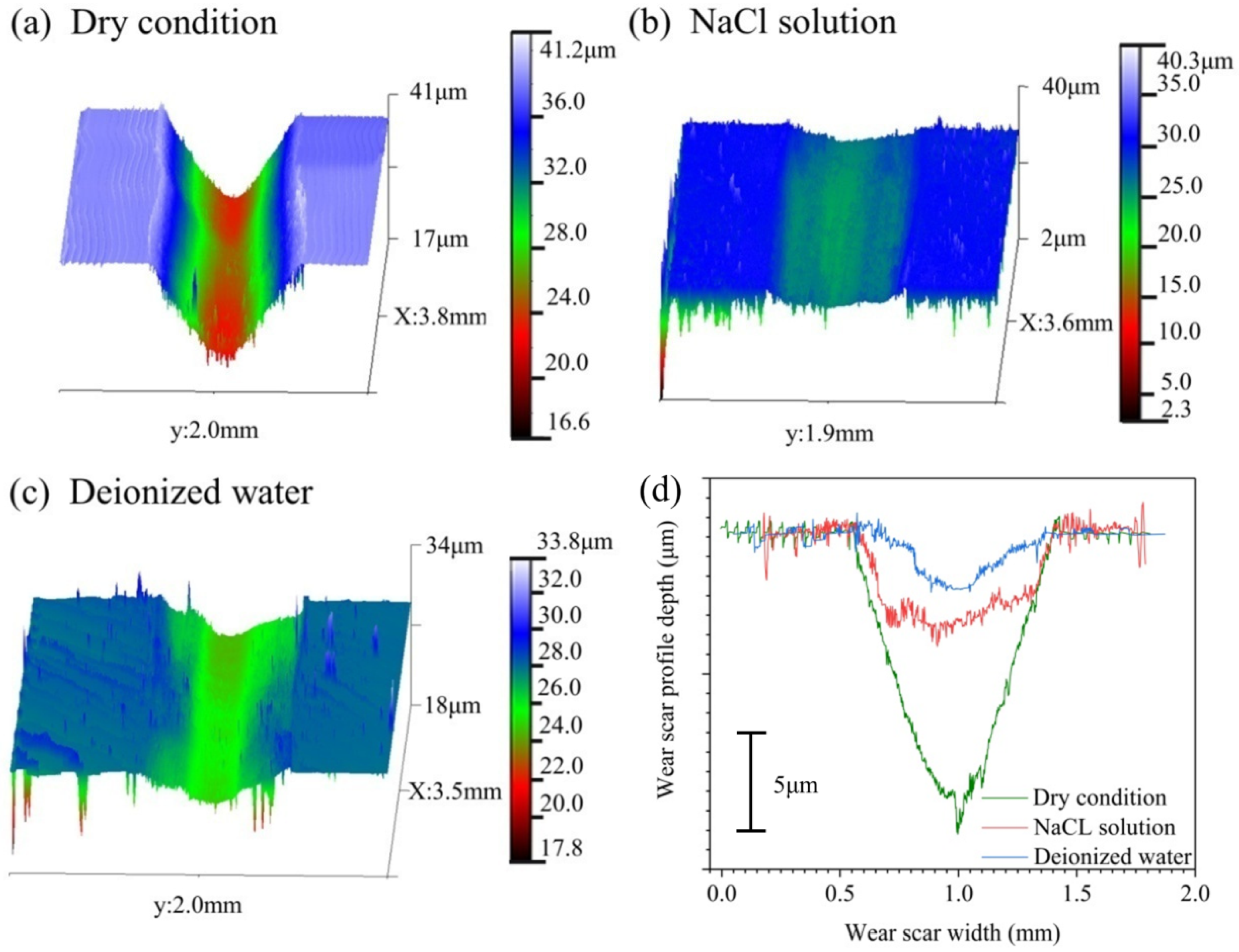
3.2. Surface Profiles, Wear Volume, and Wear Rate

Figure 3 shows the three-dimensional morphology of wear marks under different conditions when the load is 100 N and the cross-section curve of wear marks. Under the dry friction condition, the cross-sectional curves of the wear marks are “V” shaped, while in the liquid medium, they are “U” and “W” shaped. When experiencing dry friction, the abrasion marks exhibit their greatest width and depth, and the width and depth of the abrasion marks in NaCl solution are the second largest. In deionized water, the breadth and depth of the abrasion marks are the smallest. Based on the above different macroscopic morphologies, it is generally accepted that the environmental medium significantly affects the wear mechanism.
Figure 4a,b show the variation of wear volume and wear rate with load for NM500 in different environmental media, respectively. Wear-resistant steel’s wear volume and wear rate are significantly higher under dry friction conditions than in liquid media. In contrast, the wear volume and wear rate in NaCl solution are always more significant than those in deionized water. For example, when the load is 50 N, the wear volume in the air is about 5.17 times the wear volume when exposed to a NaCl solution and seven times the wear volume in deionized water. The wear rate of dry friction is about 5.14 times the wear rate in NaCl solution and seven times in deionized water. The reason for this is the lubricating and cooling properties of the liquid medium, which reduces the surface wear. In addition, the corrosion caused by NaCl solution is relatively weak, and the resulting wear leads to a product film that exhibits robust corrosion resistance and lubricating properties. Therefore, the wear of NM500 is far less severe than its wear in the air. The increase in dislocation density and surface defects is attributed to wear-induced effects on the material surface, the physicochemical activity increases, and there is an increase in the efficiency of corrosion; the surface of the corroded material is loose and porous, which is easily rubbed off by abrasives or cleaned off by liquids, thus aggravating the wear [32].
Within the same environmental medium, the wear volume increases with the load. The wear rate exhibits a trend of first decreasing and then increasing with the increase in load under both dry friction and deionized water conditions. According to the classical Archard’s law of wear, the amount of wear is inversely proportional to the hardness of the softer material in the friction pair [33,34,35,36]. Therefore, at a load of 100 N, the work-hardening effect caused by plastic deformation continuously increases the surface hardness of NM500. The wear volume of dry friction increases only slightly by 20.2%, and the wear rate decreases by 1.51 × 10⁻⁵ mm3/(N·m); the wear volume in deionized water increases by 40.8%, while the wear rate decreases by 0.16 × 10⁻⁵ mm3/(N·m). At the load of 150 N, the wear surface softens, and adhesive wear intensifies under the influence of the temperature distribution in wear-resistant steel, which is characterized by the surface temperature and the temperature gradient in the depth direction. So the wear volume under dry friction conditions showed a significant increase of 396.6%, and the wear rate increased by 5.26 × 10⁻⁵ mm3/(N·m); the wear volume in deionized water increased by 78.3%, and the wear rate increased by 0.07 × 10⁻⁵ mm3/(N·m). The wear rate of dry friction reaches a maximum value of 7.54 × 10⁻⁵ mm3/(N·m) at 150 N, and the wear rate reaches a minimum value of 0.38 × 10⁻⁵ mm3/(N·m) in deionized water at 100 N.
In NaCl solution, the wear rate increases first and then decreases with the load increase. When the load increases from 50 N to 100 N, the wear volume increases significantly by 171.2%, and the wear rate increases by 0.26 × 10⁻⁵ mm3/(N·m) due to the promotion of wear by the corrosive effect of the solution. When the load increases to 150 N, the wear volume only increases by 10.6%, and the wear rate decreases by 0.26 × 10⁻⁵ mm3/(N·m) due to the protection of the corrosion product film. The results show that under the action of 100 N load, the wear rate of wear-resistant steel in deionized water reaches the minimum value of 0.38 × 10⁻⁵ mm3/(N·m), with the best wear resistance. Thus, it seems that the environmental medium has a more significant influence on the wear resistance of NM500 wear-resistant steel.

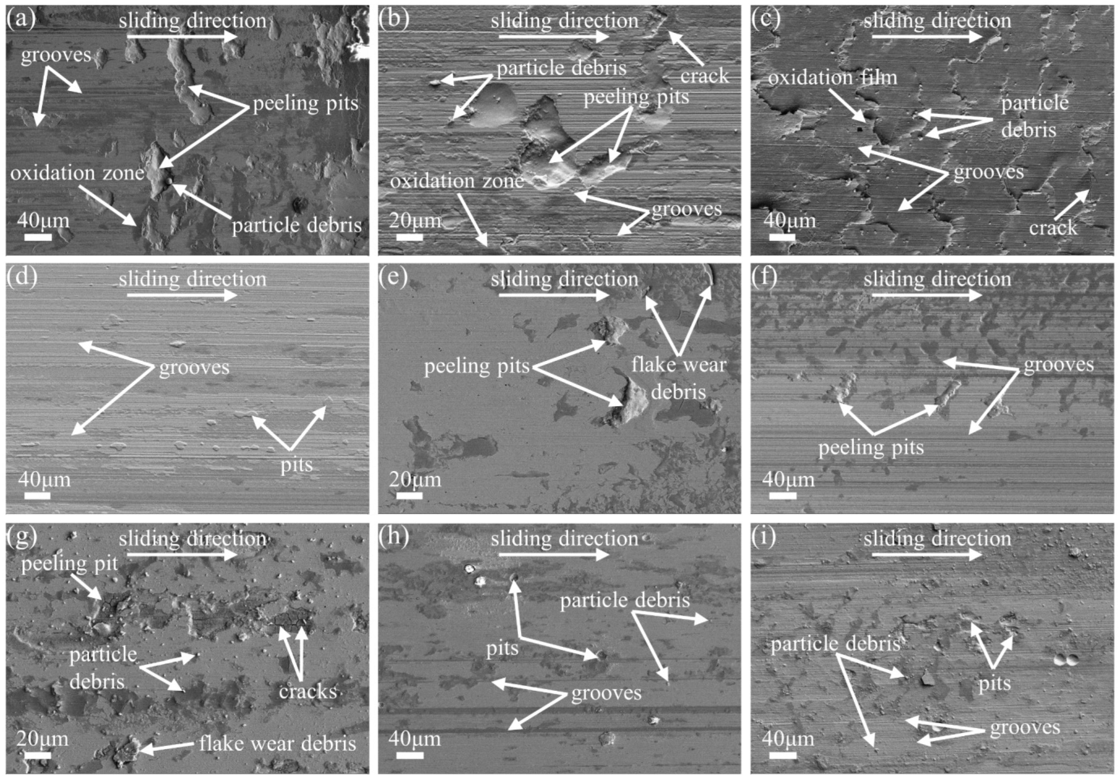
3.3. Morphologies of the Wear Surfaces

Figure 5a–c show the wear surface morphology of NM500 under dry friction conditions. It can be observed that there are peeling pits, cracks, and dark areas of oxidation on each surface. Figure 6 shows the element distribution of the wear surface under dry friction. As the observed data suggests, there is a considerable deposition of oxygen and silicon on the worn surface. Additionally, the distribution of oxygen elements coincides with the dark area in the electronic image, indicating oxidation reactions on the wear surface. The distribution of oxygen elements decreases and then increases with increasing load, indicating the presence of oxidative wear; silicon elements suggest the presence of material migration between the wear-resistant steel and the Si3N4 ceramic ball, which is a typical characteristic of adhesive wear.
In Figure 5a, peeling pits with different depths and areas are distributed on the surface, which reflects the fatigue wear mechanism. The delicate and shallow grooves parallel to the slippery direction indicate the presence of weaker abrasive wear. With the load increase, the freshly exposed surface resulting from the detachment of the oxidized area expands accordingly. The oxidative wear accelerates, decreasing the spread of oxygen elements in Figure 6. Particle debris around the peeling pit increase, and abrasive wear increases, which makes the grooves in Figure 5b obvious, and the surface roughness increases. When the load is 150 N, the wear surface in Figure 5c is covered with a layer of scale-like oxide film formed by the rolling and fusion of flake-peeling wear debris under the load. Under alternating contact stress, some lamella edges become warped, and apparent cracks are produced. The surface undergoes three-body abrasive wear as abrasive particles disperse and take part in the process, which makes groove marks more noticeable. The main wear mechanisms underneath dry friction are fatigue, adhesive, and oxidation wear.
Figure 5d–i show the wear surface morphology in the liquid medium, which is smoother than the wear surface of dry friction. The liquid’s ability to lubricate and cool enhances the anti-fatigue and anti-adhesion ability of the character. Therefore, the size and number of peeling pits on the material surface are significantly reduced, the degree of plastic deformation is reduced, and the parallel grooves caused by abrasive wear are shallower and finer than those under dry friction. Figure 7 shows the element distribution of the wear surface under liquid media. The wear surface is covered with a certain amount of silicon elements, and the migration between materials indicates the presence of adhesive wear.
In addition to adhesive wear, the wear mechanisms in deionized water also include fatigue wear and abrasive wear. In Figure 5d, the surface has scattered pitting pits and small shallow peeling pits, a typical feature of fatigue wear. During the wear process, fine and external groove marks were left by the wear debris, indicating the existence of abrasive wear. In Figure 5e, the surface shows a reduction in the peeling pits, reducing fatigue wear. The groove marks become inconspicuous. The weakening of abrasive wear has occurred. When we increase the load to 150 N, under the softening effect caused by frictional heat, the surface’s adhesive and abrasive wear in Figure 5f is aggravated. Therefore, the parallel groove widens and becomes more profound, the surface roughness increases, the friction coefficient and wear rate rise, and the peeling pits decrease.
In NaCl solution, the wear mechanism includes adhesive wear, fatigue wear, and corrosion wear. As shown in Figure 5, the wear surface in NaCl solution is the smoothest compared with other environmental conditions. The wear surface in Figure 5g is scattered with flaky and granular abrasive debris, and shallow corrosion peeling pits and cracks mark the existence of fatigue wear and corrosion wear. The crack network in the peeling pit is caused by the corrosion of the solution, which accelerates the crack propagation. With the increase of load, the fatigue wear is weakened under the dual influence of the hardening work effect and lubrication protection, and the dimples and breaks on the wear surface in Figure 5h are reduced. At the same time, the abrasive chips are changed into fine particles by repeated grinding and corrosion, which polishes the surface and accelerates the wear of NM500. Moreover, the particle wear debris leaves extremely fine and shallow groove marks, the surface roughness decreases, and the friction coefficient decreases. When the load is increased to 150 N, there are fewer pits and cracks on the wear surface in Figure 5i, and the parallel grooves become broader and more profound. At the same time, much wear debris is gathered and compacted under load to form a layer of corrosion product film, and the friction coefficient and wear rate decrease significantly.

3.4. Cross-Sectional Morphologies of the Wear and Tear Surfaces

Figure 8 shows the cross-sectional morphology of wear-resistant steel’s wear and tear surface under entirely different conditions. It is seen from the image that the morphology of the cross-section presents a layered distribution. The cross-section is composed of three parts: the reactants of the abrasive chips and environmental media are subject to a combination of mechanical mixing, chemical and thermal effects, resulting in the formation of a mechanically mixed layer (MML) [37]; the plastic deformation layer (PDL) formed due to the plastic strain caused by shear and positive force applied on the area of contact where friction occurs; and the whole substrate part.
Work hardening and grain refinement caused by plastic deformation can increase the surface hardness of materials and reduce the wear rate. Martensite that when subjected to significant plastic deformation, the material near the surface will experience elongation and become highly refined, forming a filamentous structure strain-induced surface layer that is narrowly arranged and in alignment with the worn surface [38]. The layer is also known as the layer of severe plastic deformation (SPDL layer), which can enhance the materials’ resistance to wear.
In the process of sliding wear, the formation of a mechanically mixed layer is related to the structural composition of the material, wear average load, strain degree, and other factors [38]. Not all conditions can produce a mechanically mixed layer. In this study, a mechanically mixed layer with a thickness of about 3.2~6.2 μm composed of abrasive chips and oxides is found in Figure 8c. A mechanically mixed layer with a thickness of about 3.6 μm composed of corrosion products is found in Figure 8i. Under other conditions, the mechanically mixed layer can hardly be observed. The mechanically mixed layer can play the role of lubrication protection.
Figure 9 shows the variation of NM500 plastic deformation layer depth with load in different environmental media. Under the condition of dry friction, the variation of plastic deformation layer depth is similar to that of the friction coefficient, which shows a trend of first rising and then declining. As the load increases from 50 N to 100 N, the degree of plastic deformation deepens, and the depth of the plastic deformation layer increases by 17.7 μm. The depth of the SPDL increases from 1.7 μm in Figure 8a to 3.1 μm in Figure 8b. The surface hardness of the material increases. When the load is 150 N, a mechanically mixed layer is formed on the wear surface, which reduces the degree of plastic deformation, so the depth of the plastic deformation layer decreases by 15.2 μm. The depth of the SPDL in Figure 8c decreases to 2.3 μm.
In the liquid medium, the depth of the PDL gradually deepens with the increase of load. When there is no mechanically mixed layer, the thickness of the plastic deformation layer in a liquid medium is smaller than that in air. For example, at the load of 50 N, the plastic deformation layer depth of dry friction is about 1.71 times that of NaCl solution and 2.3 times that of deionized water. This results from the liquid’s ability to lubricate and provide cooling, which weakens the adhesion ability of the friction surface and the influence of the temperature gradient along the depth direction. When the load is 150 N, the mechanically mixed layer appears under the dry friction condition, and the depth of the plastic deformation layer decreases significantly. The depth of the plastic deformation layer in the liquid medium exceeds that under the dry friction condition.
In deionized water, the plastic deformation of the contact surface layer is not apparent when the load is small, and the plastic deformation region can be observed only at the local location in Figure 8d. When the shipment is 100 N, the depth of the plastic deformation layer increases by 4μm. Meanwhile, SPDL with a depth of 1 μm appears in Figure 8e, further reducing the wear rate. When the load is increased to 150 N, the plastic deformation layer depth increases by 5.7 μm due to the influence of surface friction heat, and the growth rate of the depth value increases by 42.5%. In Figure 8f, the depth of the SPDL increases to 2 μm, indicating significant wear of the surface.
As shown in Figure 8, the NaCl solution has no obvious SPDL. This could be attributed to the combined impact of corrosion and abrasion, working in tandem, which accelerates the loss of materials and prevents the formation of SPDL on the surface. Therefore, the depths of plastic deformation layers in NaCl solution are all greater than those in deionized water when no mechanically mixed layer appears. At 50 N load, as in deionized water, only local plastic deformation can be observed in Figure 8g. With the increase in burden, the depth of the plastic deformation layer increases by 4.3 μm. The growth rate of depth value is similar to that of deionized water. When the load reaches 150 N, a mechanical mixing layer is formed on the surface, and the depth of the plastic deformation layer only increases by 1.9 μm. The growth rate of depth value decreases by 55.8%.
In the air, when the wear is light, adhesive wear is the primary mechanism, with fatigue wear and oxidation wear also being present; when the wear reaches a critical level, an oxide film is formed on the wear surface, and the predominant wear mechanism comprises of adhesive and fatigue wear. At the same time, some degree of oxidation wear is also observed. A liquid medium readily generates a lubricating film that weakens surface adhesion and thermal softening effects, impeding oxidation reactions. In deionized water, the wear mechanism is characterized by adhesive wear with some degree of fatigue and abrasive wear. In NaCl solution, adhesive and corrosion wear is the predominant mechanisms with some accompanying fatigue wear.

4. Conclusions

The researchers systematically investigated the friction and wear behavior of NM500 steel under sliding wear tests in air atmosphere, deionized water, and 3.5wt% NaCl solution conditions. The following conclusions can be drawn:
  • Under dry friction conditions, the friction coefficient and wear rate of NM500 are much higher than those under other conditions. The maximum friction coefficient of 0.6 can be obtained at 100 N, and the maximum wear rate of 7.54 × 10⁻⁵ mm3/(N·m) is received at 150 N. In the liquid medium environment, NM500 wear-resistant steel in NaCl solution has the lowest friction coefficient and obtains the minimum value of 0.39 at 150 N; in deionized water, wear-resistant steel has the lowest wear rate and brings the minimum value of 0.38 × 10⁻⁵ mm3/(N·m) at 100 N. Therefore, the wear resistance of NM500 steel is the best in deionized water (100 N) and the worst in dry friction;
  • Under dry friction conditions, the wear mechanism of NM500 steel is mainly adhesive wear, fatigue wear, and oxidation wear. The wear process in deionized water is dominated by adhesive wear as the primary mechanism, accompanied by some degree of fatigue wear and abrasive wear as secondary mechanisms. The wear mechanism prevailing in the NaCl solution is predominantly ascribed to corrosion and adhesive wear, with a small amount of fatigue wear;
  • When there is no mechanically mixed layer, the magnitude of the plastic deformation layer’s thickness in dry friction is about 2~3 times that in the liquid environment under the same load. This is because the lubrication and cooling action of liquid affects the work hardening and the surface’s tendency to undergo thermal softening and also causes the reduction of the friction coefficient and wear rate. In addition, the corrosion of the NaCl solution is the main reason for the lowest friction coefficient and higher wear rate of wear-resistant steel.

Author Contributions

Conceptualization, G.W.; analysis, G.W.; investigation, H.Z.; data curation, Y.Z.; writing—original draft preparation, G.W.; writing—review and editing, G.W. and G.Z.; supervision, J.W. and Y.Z.; funding acquisition, L.M. and G.Z. All authors have read and agreed to the published version of the manuscript.

Funding

This work was supported by the National Natural Science Foundation of China (U1910213), the Fundamental Research Program of Shanxi Province (20210302123207 and 20210302124009), Scientific and Technological Innovation Programs of Higher Education Institutions in Shanxi (2021L292), Taiyuan University of Science and Technology Scientific Research Initial Funding (20212026).

Data Availability Statement

Not applicable.

Acknowledgments

The authors would like to thank Shanxi Provincial Key Laboratory of Metallur-gical Device Design Theory and Technology for providing financial support for this research.

Conflicts of Interest

The authors declare no conflict of interest.

References

  1. Wei, S.; Xu, L. Review on research progress of steel and iron wear-resistant materials. Acta Metall. Sin. 2020, 56, 523–538. [Google Scholar]
  2. Deng, X.; Wang, Z.; Han, Y.; Zhao, H.; Wang, G. Microstructure and Abrasive Wear Behavior of Medium Carbon Low Alloy Martensitic Abrasion Resistant Steel. J. Iron Steel Res. Int. 2014, 21, 98–103. [Google Scholar] [CrossRef]
  3. Xue, H.; Zhang, Y.; Zhu, M.; Yin, X.; Zhang, W.; Liu, S. The size effect of martensite laths and precipitates on high strength wear-resistant steels. Mater. Res. Express. 2021, 8, 126528. [Google Scholar] [CrossRef]
  4. Konat, Ł.; Zemlik, M.; Jasiński, R.; Grygier, D. Austenite Grain Growth Analysis in a Welded Joint of High-Strength Martensitic Abrasion-Resistant Steel Hardox 450. Materials 2021, 14, 2850. [Google Scholar] [CrossRef] [PubMed]
  5. Hietala, M.; Ali, M.; Khosravifard, A.; Keskitalo, M.; Järvenpää, A.; Hamada, A. Optimization of the tensile-shear strength of laser-welded lap joints of ultra-high strength abrasion resistance steel. JMR&T 2021, 11, 1434–1442. [Google Scholar]
  6. Kaijalainen, A.; Hautamäki, I.; Kesti, V.; Pikkarainen, T.; Tervo, H.; Mehtonen, S.; Porter, D.; Kömi, J. The Influence of Microstructure on the Bendability of Direct Quenched Wear Resistant Steel. Steel Res. Int. 2019, 90, 1900059. [Google Scholar] [CrossRef]
  7. Damião, C.A.; Alcarria, G.C.; Teles, V.C.; de Mello, J.D.B.; da Silva, W.M., Jr. Influence of metallurgical texture on the abrasive wear of hot-rolled wear resistant carbon steels. Wear 2019, 426–427, 101–111. [Google Scholar] [CrossRef]
  8. Bratkovsky, E.V.; Shapovalov, A.N.; Dema, R.R.; Kharchenko, M.V.; Platov, S.I.; Rubanik, V.V. Evaluation Method of Impact and Abrasive Steel Resistance. J. Frict. Wear 2019, 40, 133–138. [Google Scholar] [CrossRef]
  9. Naseema, S.; Gaurav, B.; Das, G.; Srivatsava, V.C.; Rao, K.S.; Krishna, K.G. TEM Analysis of Precipitates in a Low Alloy Wear Resistant Steel and Correlating with its Corrosion Behaviour. Adv. Mater. Res. 2018, 1148, 77–81. [Google Scholar] [CrossRef]
  10. Erding, W.; Song, R.; Xiong, W. Effect of Tempering Temperature on Microstructures and Wear Behavior of a 500 HB Grade Wear-Resistant Steel. Metals 2019, 9, 45. [Google Scholar]
  11. Huang, L.; Deng, X.; Li, C.; Jia, Y.; Wang, Q.; Wang, Z. Effect of TiC particles on three-body abrasive wear behaviour of low alloy abrasion-resistant steel. Wear 2019, 434–435, 202971. [Google Scholar] [CrossRef]
  12. Deng, X.; Huang, L.; Wang, Q.; Fu, T.; Wang, Z. Three-body abrasion wear resistance of TiC-reinforced low-alloy abrasion-resistant martensitic steel under dry and wet sand conditions. Wear 2020, 452–453, 203310. [Google Scholar] [CrossRef]
  13. Huang, L.; Deng, X.; Wang, Q.; Wang, Z. Microstructure, Mechanical Properties and Wear Resistance of Low Alloy Abrasion Resistant Martensitic Steel Reinforced with TiC Particles. ISIJ Int. 2020, 60, 2586–2595. [Google Scholar] [CrossRef]
  14. Liu, L.; Liang, X.; Liu, J.; Sun, X. Precipitation Process of TiC in Low Alloy Martensitic Steel and Its Effect on Wear Resistance. ISIJ Int. 2020, 60, 168–174. [Google Scholar] [CrossRef]
  15. Kostryzhev, A.G.; Killmore, C.R.; Yu, D.; Pereloma, E.V. Martensitic wear resistant steels alloyed with titanium. Wear 2020, 446–447, 203203. [Google Scholar] [CrossRef]
  16. Ayyagari, A.; Barthelemy, C.; Gwalani, B.; Banerjee, R.; Scharf, T.W.; Mukherjee, S. Reciprocating sliding wear behavior of high entropy alloys in dry and marine environments. Mater. Chem. Phys. 2018, 210, 162–169. [Google Scholar] [CrossRef]
  17. Wieczorek, A.N.; Jonczy, I.; Bała, P.; Stankiewicz, K.; Staszuk, M. Testing the Wear Mechanisms of the Components of Machines Used in Fossil Energy Resource Extraction. Energies 2021, 14, 2125. [Google Scholar] [CrossRef]
  18. Lindroos, M.; Apostol, M.; Kuokkala, V.T.; Laukkanen, A.; Valtonen, K.; Holmberg, K.; Oja, O. Experimental study on the behavior of wear resistant steels under high velocity single particle impacts. Int. J. Impact Eng. 2015, 78, 114–127. [Google Scholar] [CrossRef]
  19. Rastegar, V.; Karimi, A. Surface and subsurface deformation of wear-resistant steels exposed to impact wear. J. Mater. Eng. Perform. 2014, 23, 927–936. [Google Scholar] [CrossRef]
  20. Valtonen, K.; Keltamäki, K.; Kuokkala, V.T. High-stress abrasion of wear resistant steels in the cutting edges of loader buckets. Tribol. Int. 2018, 119, 707–720. [Google Scholar] [CrossRef]
  21. Ojala, N.; Valtonen, K.; Antikainen, A.; Kemppainen, A.; Minkkinen, J.; Oja, O.; Kuokkala, V.-T. Wear performance of quenched wear resistant steels in abrasive slurry erosion. Wear 2016, 354–355, 21–31. [Google Scholar] [CrossRef]
  22. Magnol, R.V.; Gatti, T.; Romero, M.C.; Sinatora, A.; Scandian, C. Liquid media effect on the abrasion response of WC/Co hardmetal with different cobalt percent. Wear 2021, 477, 203815. [Google Scholar] [CrossRef]
  23. Wieczorek, A.N.; Jonczy, I.; Filipowicz, K.; Kuczaj, M.; Pawlikowski, A.; Łukowiec, D.; Staszuk, M.; Gerle, A. Study of the Impact of Coals and Claystones on Wear-Resistant Steels. Materials 2023, 16, 2136. [Google Scholar] [CrossRef] [PubMed]
  24. Laukkanen, A.; Lindgren, M.; Andersson, T.; Pinomaa, T.; Lindroos, M. Development and validation of coupled erosion-corrosion model for wear resistant steels in environments with varying pH. Tribol. Int. 2020, 151, 106534. [Google Scholar] [CrossRef]
  25. Kalácska, Á.; De Baets, P.; Hamouda, H.B.; Theuwissen, K.; Sukumaran, J. Tribological investigation of abrasion resistant steels with martensitic and retained austenitic microstructure in single- and multi–asperity contact. Wear 2021, 482–483, 203980. [Google Scholar] [CrossRef]
  26. Xu, Z.; Huang, Z.; Wang, Y.; Lin, C.; Xu, X. Friction and Wear Behavior of C17200 Copper-Beryllium Alloy in Dry and Wet Environments. J. Mater Eng. Perform. 2021, 30, 7542–7551. [Google Scholar] [CrossRef]
  27. Zhang, Z.; Ji, G.; Shi, Z. Tribological properties of ZrO2 nanofilms coated on stainless steel in a 5% NaCl solution, distilled water and a dry environment. Surf. Coat. Technol. 2018, 350, 128–135. [Google Scholar] [CrossRef]
  28. Liu, Y.; Ma, S.; Gao, M.C.; Zhang, C.; Zhang, T.; Yang, H.; Wang, Z.; Qiao, J. Tribological properties of AlCrCuFeNi 2 high-entropy alloy in different conditions. Metall. Mater. Trans. A 2016, 47, 3312–3321. [Google Scholar] [CrossRef]
  29. Zhao, G.; Li, J.; Zhang, R.; Li, H.; Li, J.; Ma, L. Wear behavior of copper containing antibacterial stainless steel in different environmental media and EBSD analysis of its sub surface structure. Mater. Charact. 2023, 197, 112690. [Google Scholar] [CrossRef]
  30. Wang, M.; Wang, Y.; Wang, J.; Fan, N.; Yan, F. Effect of Heat Treatment Temperature and Lubricating Conditions on the Fretting Wear Behavior of SAF 2507 Super Duplex Stainless Steel. ASME J. Tribol. 2019, 141, 101601. [Google Scholar] [CrossRef]
  31. Greer, A.L.; Rutherford, K.L.; Hutchings, I.M. Wear resistance of amorphous alloys and related materials. Int. Mater. Rev. 2002, 47, 87–112. [Google Scholar] [CrossRef]
  32. Li, X.; Zhou, Y.; Cao, H.; Li, Y.; Wang, L.; Wang, S. Wear behavior and mechanism of H13 steel in different environmental media. J. Mater. Eng. Perform. 2016, 25, 4134–4144. [Google Scholar] [CrossRef]
  33. Varenberg, M. Adjusting for running-in: Extension of the Archard wear equation. Tribol. Lett. 2022, 70, 59. [Google Scholar] [CrossRef]
  34. Yilmaz, N.G.; Goktan, R.M.; Onargan, T. Correlative relations between three-body abrasion wear resistance and petrographic properties of selected granites used as floor coverings. Wear 2016, 372–373, 197–207. [Google Scholar] [CrossRef]
  35. Verbeek, H.J. Tribological systems and wear factors. Wear 1979, 56, 81–92. [Google Scholar] [CrossRef]
  36. Archard, J.F. Contact and rubbing of flat surfaces. J. Appl. Sci. 1953, 24, 981–988. [Google Scholar] [CrossRef]
  37. Kapoor, A.; Franklin, F.J. Tribological layers and the wear of ductile materials. Wear 2000, 245, 204–215. [Google Scholar] [CrossRef]
  38. Cao, Y.; Yin, C.; Liang, Y.; Tang, S. Lowering the coefficient of martensite steel by forming a self-lubricating layer in dry sliding wear. Mater. Res. Express 2019, 6, 055024. [Google Scholar] [CrossRef]
Figure 1. Schematic illustration of friction and wear test: (a) reciprocating sliding, (b) liquid condition.
Crystals 13 00770 g001
Figure 2. Friction coefficient of the NM500 wear-resistant steel at 50, 100, and 150 N in different conditions: (a) dry condition, (b) deionized water, (c) and NaCl solution.
Crystals 13 00770 g002
Figure 3. 3D morphology (ac) and wear scar cross-section curve (d) of the wear surfaces generated in different conditions (100 N).
Crystals 13 00770 g003
Figure 4. Wear results of the NM500 wear−resistant steel at various loads with the corresponding environment: (a) wear volume and (b) wear rate.
Crystals 13 00770 g004
Figure 5. Scanning electron microscopy images of the wear surfaces: (a) dry condition-50 N, (b) dry condition-100 N, (c) dry condition-150 N, (d) deionized water-50 N, (e) deionized water-100 N, (f) deionized water-150 N, (g) NaCl solution-50 N, (h) NaCl solution-100 N, and (i) NaCl solution-150 N.
Crystals 13 00770 g005
Figure 6. Elemental mapping of O, Si on the wear surfaces of the NM500 wear-resistant steel in dry conditions for 50 N (ac), 100 N (df), and 150 N (gi).
Crystals 13 00770 g006
Figure 7. Elemental mapping of Si on the wear surfaces of the NM500 wear-resistant steel in liquid condition: (a) NaCl solution-50 N, (b) NaCl solution-100 N, (c) deionized water-150 N, (d) NaCl solution-50 N, (e) NaCl solution-100 N, and (f) deionized water-150 N.
Crystals 13 00770 g007
Figure 8. Cross-sectional morphology of the wear surfaces of the NM500 steel under different conditions: (a) dry condition-50 N, (b) dry condition-100 N, (c) dry condition-150 N, (d) deionized water-50 N, (e) deionized water-100 N, (f) deionized water-150 N, (g) NaCl solution-50 N, (h) NaCl solution-100 N, and (i) NaCl solution-150 N. (MML: mechanically mixed layer; PDL: plastic deformation layer; SPDL: severe plastic deformation layer).
Crystals 13 00770 g008
Figure 9. Variation of plastic deformation layer depth of the NM500 wear-resistant steel at various loads with the corresponding environment.
Crystals 13 00770 g009
Table 1. Chemical composition of NM500 (wt%).
CSiMnPSCrNiMoTiBALs
0.380.701.700.0200.0101.201.000.650.0500.000450.010
Disclaimer/Publisher’s Note: The statements, opinions and data contained in all publications are solely those of the individual author(s) and contributor(s) and not of MDPI and/or the editor(s). MDPI and/or the editor(s) disclaim responsibility for any injury to people or property resulting from any ideas, methods, instructions or products referred to in the content.

