Article

Room and Elevated Temperature Sliding Friction and Wear Behavior of Al0.3CoFeCrNi and Al0.3CuFeCrNi2 High Entropy Alloys

by
Dheyaa F. Kadhim
1,2,
Manindra V. Koricherla
2 and
Thomas W. Scharf
2,*
1
Department of Mechanical Engineering, University of Thi-Qar, Nasiriyah 64001, Iraq
2
Department of Materials Science and Engineering, The University of North Texas, Denton, TX 76207, USA
*
Author to whom correspondence should be addressed.
Crystals 2023, 13(4), 609; https://doi.org/10.3390/cryst13040609
Submission received: 17 February 2023 / Revised: 26 March 2023 / Accepted: 30 March 2023 / Published: 2 April 2023
(This article belongs to the Special Issue Intermetallic Compound (Volume II))

Abstract

:
In this study, processing–structure–property relations were systematically investigated at room and elevated temperatures for two FCC Al0.3CoFeCrNi and Al0.3CuFeCrNi2 high-entropy alloys (HEAs), also known as complex concentrated alloys (CCAs), prepared by conventional arc-melting. It was determined that both alloys exhibit FCC single-phase solid solution structure. Micro-indentation and sliding wear tests were performed to study the hardness and tribological behavior and mechanisms at room and elevated temperatures. During room-temperature sliding, both alloys exhibit similar friction behavior, with an average steady-state coefficient of friction (COF) of ~0.8. Upon increasing sliding temperatures to 300 °C, the average COF decreased to a lowest value of ~0.3 for Al0.3CuFeCrNi2. Mechanistic wear studies showed this was due to the low interfacial shear strength tribofilms formed inside the wear tracks. Raman spectroscopy and energy dispersive spectroscopy determined the tribofilms were predominantly composed of binary oxides and multi-element solid solution oxides. While the tribofilms at elevated temperatures lowered the COF values, the respective wear rates in both alloys were higher compared to room-temperature sliding, due to thermal softening during 300 °C sliding. Thus, these single FCC-phase HEAs provide no further benefit in wear resistance at elevated temperatures, and likely will have similar implications for other single FCC-phase HEAs.

1. Introduction

In recent years, numerous metallic alloys have been studied that contain multiple principal and equimolar elements, typically with five or more major constituents in the range of 5–35 at. %. This new approach to designing such alloys with multiple principal elements has led to the emergence of high-entropy alloys (HEAs), which were proposed by Yeh et al. [1] and Cantor et al. [2], and have more recently been denoted as complex concentrated alloys (CCAs) [3,4]. Unlike conventional alloys, core effects are present, such as high entropy, lattice distortion, sluggish diffusion, and cocktail effects [1,2,3,4]. The high-entropy effect results from the higher configurational entropy in these alloys compared to conventional alloys. Due to the high entropy of mixing, these alloys may favor the formation of simple solid solutions and prevent the generation of hard but brittle intermetallic compounds. As a result, these alloys can exhibit superior wear, oxidation and corrosion resistance, as well as high-temperature strength [3,4,5,6]. Moreover, recent studies have indicated that Al0.5CoCrCuFeNiTix, AlxCoCrCuFeNi and AlCoCrFeNiTix HEAs exhibit a variety of microstructures and mechanical properties, with face-centered cubic (FCC), body-centered cubic (BCC) structures, or a mixture of both [7,8].
According to studies on the tribological performance of HEAs, composition is a key factor in wear resistance. The effect of Al addition on the FeCoCrNiAlx HEA was examined by Liu et al. [9], who concluded that the wear mechanisms changed from previously mixed wear modes of abrasive, adhesive, and oxidative wear to a mixture of abrasive and oxidative wear. Such a change shows that the FeCoCrNiAlx HEA coating’s wear resistance was significantly enhanced by the addition of Al. In a tribological study of Al0.65CoCrFeNi, Miao et al. [10] found that only abrasive wear features could be seen on the remelted layer, whereas adhesive wear predominated on the substrate. As a result, the average friction coefficient and wear rate of the remelted layer were reduced by 23% and 80%, respectively, compared to the substrate. Wu et al. [11] reported on the adhesive wear behavior of AlxCoCrCuFeNi alloys, showing that increasing the aluminum content resulted in the HEA structure transforming from FCC to BCC phases, subsequently raising the hardness value and lowering the wear rate. In addition, a low Al percentage has been found to favor a single-phase FCC lattice in the well-studied AlxCoCrFeNi HEA, whereas a greater Al fraction results in a BCC phase [12].
The well-studied AlxCoCrFeNi HEA system microstructures have been shown to change from having a single FCC phase to a single BCC phase with increasing Al content, with the Al0.3CoCrFeNi HEA being the only one to form a solid solution with an FCC structure. This particular HEA will serve as a baseline alloy in the present study. According to several studies, this HEA exhibits good mechanical properties such as high plasticity, work-hardening capacity, and a balance between cryogenic strength and ductility [13,14,15,16]. Due to the inherent property of the FCC structure, Al0.3CoCrFeNi HEA has a relatively low strength at ambient temperature, with a room-temperature yield strength between 150 and 350 MPa [13]; its melting point is at 1870 K [14]. The mechanical properties of Al0.3CoCrFeNi HEAs have been significantly improved through the application of thermo-mechanical processing techniques, such as cold rolling and subsequent annealing. For example, with 90% cold rolling and 550 °C annealing, Gwalani et al. [15] produced a more complex microstructure with hierarchical features of ultra-fine grains, fine-scale B2 and σ precipitates, and nanoclusters that resulted in the tensile yield strength significantly increasing from 160 to 1800 MPa. The fully recrystallized states along with grain refinement strengthening and precipitation strengthening were the focus of earlier investigations into strengthening FCC Al0.3CoCrFeNi HEAs. Jiao et al. [16] used instrumented nanoindentation to examine the mechanical characteristics of Al0.3CoCrFeNi and AlCoCrFeNi HEAs over a wide range of loading rates to determine an excellent combination of strength and ductility.
Based on the above studies, Al0.3CoFeCrNi HEAs exhibit a good balance of mechanical properties, so their effects on tribological properties are of interest. However, there have been limited systematic investigations on the room-temperature friction and wear behavior and mechanisms of single FCC-phase Al0.3CoFeCrNi, and no studies on Al0.3CuFeCrNi2 HEA. Additionally, the tribological behavior and mechanistic studies are unknown for these alloys at elevated temperatures, at which alternative structural alloys are of interest to replace bearing steels, such 440C and 52100, which oxidize and form iron oxide deleterious phases. It is at elevated temperatures such as 300 °C, used in this study, that mechanical and tribological processes begin to occur in metallic alloys, such as thermal softening and tribochemical (oxidation) reactions, respectively. Therefore, the objective of the present study was to investigate the influence and mechanisms of Ni content on the tribological properties and corresponding tribofilm evolution of Al0.3CoFeCrNi and Al0.3CuFeCrNi2 HEAs, both at room temperature and during 300 °C sliding.

2. Experimental Methods

Two alloys with different Ni content and containing Co or Cu were studied: Al0.3CoFeCrNi (A1) and Al0.3CuFeCrNi2 (A2). Alloy ingots were prepared by arc-melting and casting. The mixtures of the alloying elements with purities higher than 99.5 wt.% were melted in an argon atmosphere several times to improve the chemical homogeneity of the ingots in the liquid state. Both alloys were cold rolled to a 20% reduction in thickness with ten passes and solutionized at 1150 °C for 30 min, followed by water-quenching for homogenization. For microstructural and property investigation, the samples were ground and polished by standard metallographic techniques to dimensions of approximately 19 mm (length) × 14 mm (width) × 7 mm (thick) with mass of ~14 g. Surface microstructural characterization was carried out in a field emission gun scanning electron microscope (SEM) using a FEI Nova 200 dual-beam SEM. The SEM is also equipped with energy dispersive x-ray spectroscopy (EDS) for chemical analysis of the alloys before and after sliding (wear track maps). Room and elevated temperature (300 °C after the sliding tests) microhardness measurements were performed using a Shimadzu Vickers hardness indenter with a normal load of 9.807 N at a hold time of 10 s. A total of ten measurements were recorded for both alloys at spacings of ~1 mm apart.
The friction behavior of both alloys was Investigated using a Falex ISC-200 pin-on-disk tribometer, following the ASTM G99 standard. The sliding coefficient of friction (COF) was measured at room and elevated (300 °C) temperature in lab air (40% relative humidity). The current study was limited to 300 °C sliding since elevated temperature studies require a significant amount of time. The HEAs were tested in unidirectional sliding against a Si3N4 ball counterface (3.175 mm diameter) with hardness of 22 GPa to avoid ball wear and transfer to the wear tracks. The sliding speed was 8.5 mm/s for all tests, with a normal load of 0.25 N. Based on these values, the initial maximum Hertzian contact stress is ~0.6 GPa, which was chosen to be below the yield strength of these alloys. The total sliding distance was 200 m for all tests that took about 6 h. At least three measurements were made for each HEA for repeatability purposes. After each test, an optical microscope was used to image the worn surfaces of the HEAs and the Si3N4 counterfaces. A stylus surface profilometer (Veeco Dektak 150 Profilometer) was used to measure wear track depths. At least eight profilometry traces were taken across each wear scar to obtain the cross sectional worn area. The wear factor/rate was calculated as the removed volume loss divided by the applied load and the total sliding distance. The volume loss can be calculated by multiplying the area of the worn surface by the circumference of the circular wear track, assuming uniform wear. Crystal structures were identified with an X-ray diffractometer (Rigaku Ultima III) under radiation conditions of 30 kV, 20 mA, a CuKα anode, and a scanning speed of 2 degrees/minute. Representative wear surfaces were analyzed using SEM and EDS to acquire both secondary electron (SE) and backscatter electron (BSE) images as well as elemental wear maps, respectively. In addition, a Raman spectrometer (Thermo Electron Almega XR) was used to determine tribo-chemical phases on the wear surfaces using a 532 nm laser wavelength.

3. Results and Discussion

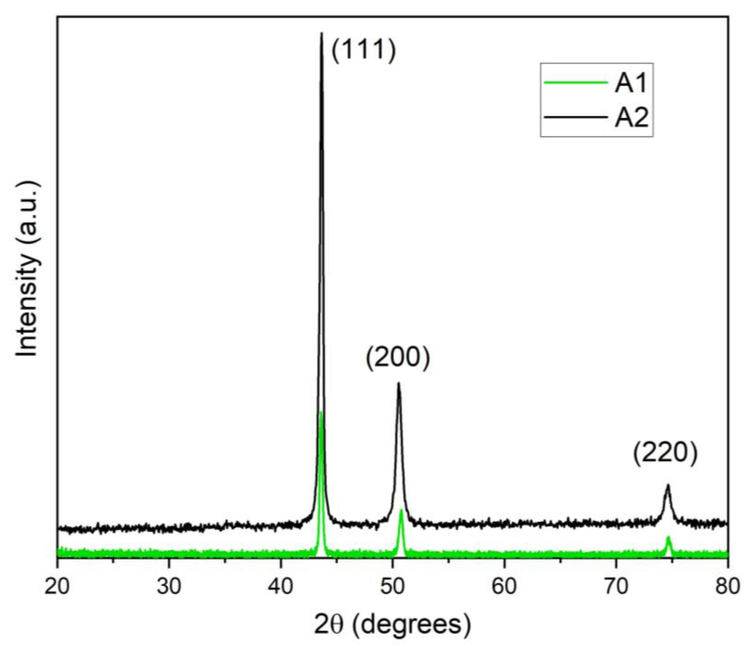
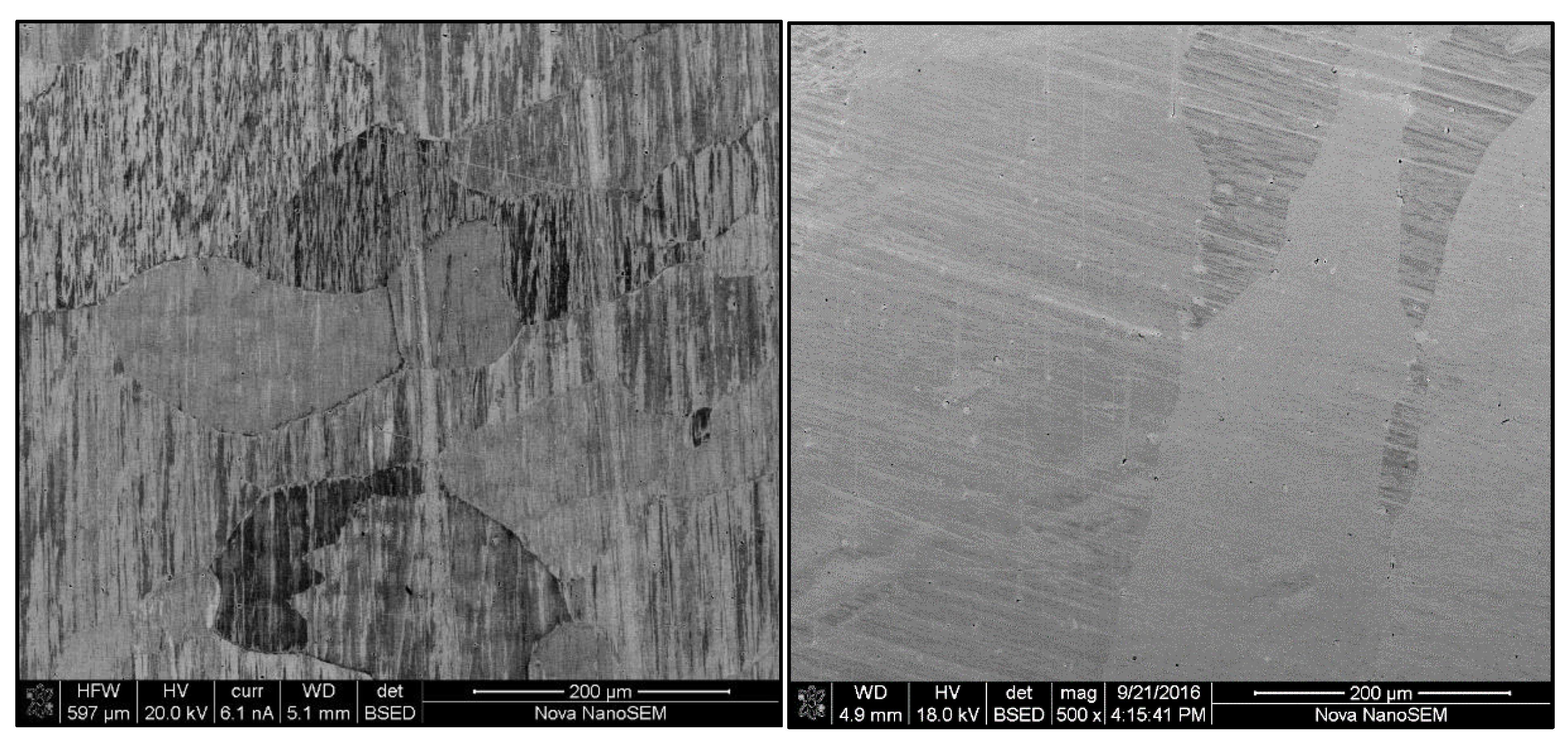
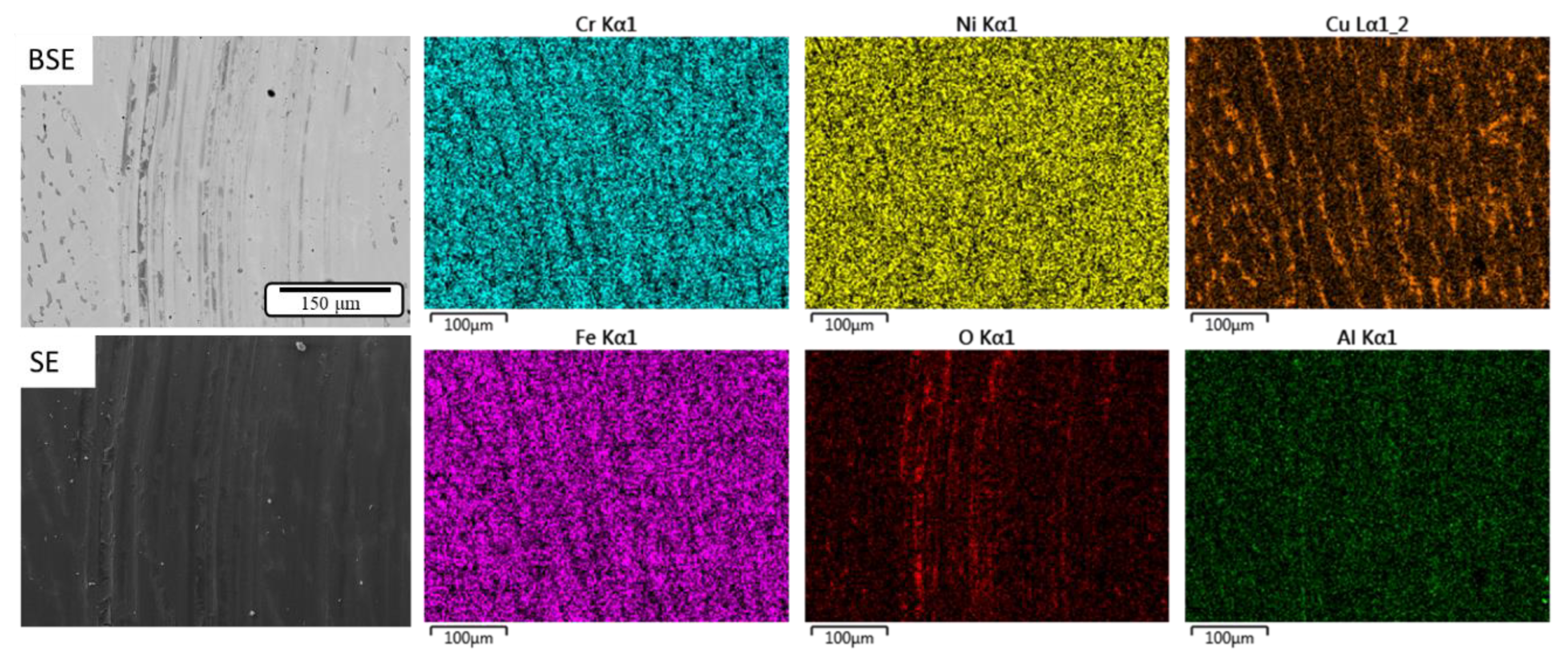
3.1. Microstructure and Phase Analysis

Figure 1 shows the XRD scans of the Al0.3CoFeCrNi (A1) and Al0.3CuFeCrNi2 (A2) HEAs. It is evident there is one set of fundamental FCC reflections that verifies an FCC solid solution crystal structure without the presence of secondary phases. Using the indexed (111) reflections, the lattice constants (a) for A1 and A2 alloys are calculated to be 3.591 Å and 3.589 Å, respectively. Based on the resolution of the x-ray diffractometer, these values are within experimental error, and thus there are no lattice parameter differences between the two single FCC-phase HEAs. These HEAs retain a single phase at higher temperatures when cooled rapidly due to the entropy of too many alloying elements, along with sluggish diffusion kinetics.
Figure 2 and Table 1 show representative SEM images and corresponding EDS chemical analysis, respectively, of the A1 and A2 alloys. The alloys exhibit microcrystalline structures with elongated grains (sizes in the range of 300–600 µm) and have no compositional segregation. Wang et al. [8] also reported that as-cast Al0.3CoCrFeNi HEA has an FCC single phase with a columnar microstructure. Similarly, Kao et al. [17] determined that Al0.37CoCrFeNi has an FCC single-phase crystal structure, also shown by Guo et al. [18] for AlxCrCuFeNi2 HEAs. The latter authors also determined that Al0.5CrCuFeNi2 alloy exhibits a dendritic microstructure. The SEM images in Figure 2 show evidence of possible interdendritic and dendritic regions retaining an FCC phase with high closeness in the lattice constants, also reported in [19,20]. Ng et al. [21] showed that a Al0.5CrCuFeNi2 alloy exhibits an FCC single phase, but due to XRD peak overlaps, they surmised there were two disordered FCC phases with very close lattice parameters at ~3.59 Å, which is equivalent to the above calculated lattice parameters for A1 and A2 alloys. Gwalani et al. [22] determined with transmission electron microscopy and selected area diffraction patterns that Al0.3CuFeCrNi2 (with the same composition as A2 alloy) has an FCC-type solid solution at ambient temperature. They further stated the high mixing entropy and sluggish effects that decrease the Gibbs energy develop a solid solution rather than intermetallic compounds, and as a result were surmised to be the reasons for the formation of a single solid solution instead of intermetallic compounds [22]. From a thermodynamic point of view, the mixing enthalpy overcomes and leads to decomposition in the matrix to form two phases.

3.2. Microhardness

It is crucial to assess the hardness of the material in order to understand the likely underlying wear process, since material hardness is often correlated to wear resistance [23]. Table 2 lists the averaged microhardness values for the A1 and A2 alloys at room temperature (RT) and 300 °C (acquired after the sliding wear tests and outside the wear tracks). Both alloys exhibit similar RT hardness values. However, at 300 °C, there is thermal softening in A1 and hardening in A2 that could be due to Ni content differences, resulting in the likely formation of a harder NiO scale on the A2 alloy. In addition, Qiu et al. [24] determined that adding more Ni to Al2CrFeCoCuTiNix HEAs resulted in increasing RT microhardness and strength. They attributed this increase to the Ni content that increased the content of the BCC crystal structure in the alloys. In contrast, López Ríos et al. [25] reported that because of Cr and Fe precipitates dissolving in the nickel-rich matrix and forming a stable solid solution, the hardness values for AlCrFeCoNi decreased to 562 HV, 455 HV, and 316 HV, with reduction in nickel concentration. Kuo et al. [26] determined that a CuFeTiZrNi0.1 alloy exhibits a microhardness of 935 HV, wherein increasing the FCC phase in the alloy is correlated to an increase in the Ni content. Therefore, they concluded that the low hardness of the FCC phase causes the alloy’s hardness to gradually decrease with increasing Ni content; however, the hardness was not measured at elevated temperatures, e.g., at 300 °C, where the effects of oxide scales and thermal softening can influence the microhardness values.

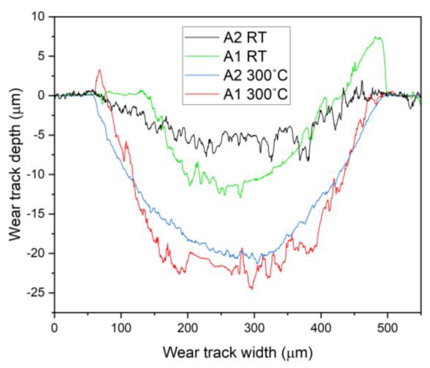
3.3. Friction and Wear Behavior

Table 3 lists the averaged steady-state COF and wear factor values for A1 and A2 alloys during RT and 300 °C sliding. The RT COF values of ~0.8 for both alloys during steady-state sliding are relatively high friction values that are consistent with Si3N4 sliding on Ni and other metallic materials [27,28]. However, these values are considerably higher than other HEAs with hard secondary phases; for example, COF values of ~0.3 were observed in HEA Al0.25Ti0.75CoCrFeNi [29], since harder alloys exhibit a smaller real area of sliding contact, thereby leading to lower frictional forces. The high RT friction behavior of both alloys is due to the single FCC phase being relatively soft, which is corroborated by the relatively low hardness values listed in Table 2. During sliding at 300 °C, the averaged COF values decreased for both alloys, but considerably more in the A2 alloy, which will be further discussed in the next section.
Representative cross-sectional wear track depth and width profiles are shown in Figure 3 for A1 and A2 alloys acquired after sliding at RT and 300 °C. It is evident that during RT sliding, the alloys exhibit a smaller worn area compared to sliding at 300 °C, despite the higher COF values. The cross sectional worn areas were used to calculate the corresponding wear factors listed in Table 3. The wear factors listed in Table 3 agree well with the RT COF trends, i.e., there are similar wear factors for both alloys at RT. However, during 300 °C sliding, there is a slightly lower wear factor for the A2 alloy, since there was no thermal softening, as evidenced by the increase in hardness. Compared to RT sliding wear factors, both alloys have higher wear factors, suggesting that in addition to hardness, there are other factors active that will be discussed in the next section. Since both HEAs exhibit single FCC-phase structures without the presence of typical secondary phases present in structural alloys, e.g., hard intermetallic or carbide phases, the wear factors are about an order of magnitude higher. For example, the aforementioned Al0.25Ti0.75CoCrFeNi BCC HEA has hard intermetallic L21 and χ phases responsible for lower sliding wear rates in the order of 1 × 10⁻⁵ mm3/N·m [29]. However, a similar single FCC-phase HEA Al0.1CoCrFeNi to that of A1 alloy, but with lower Al content and slightly softer, exhibits a higher RT sliding wear factor of 1.9 × 10⁻⁴ mm3/N·m [30]. Based on the above, single FCC-phase HEAs do not provide adequate wear resistance compared to HEAs with hard secondary phases, making them similar to other structural alloys such as bearing steels with chromium carbide precipitates. Only when hard secondary phases are present do HEAs such as Al0.25Ti0.75CoCrFeNi have comparable wear rates to those measured for chromium carbide bearing steel 440C, values of ~1 × 10⁻⁵ mm3/N·m [29].

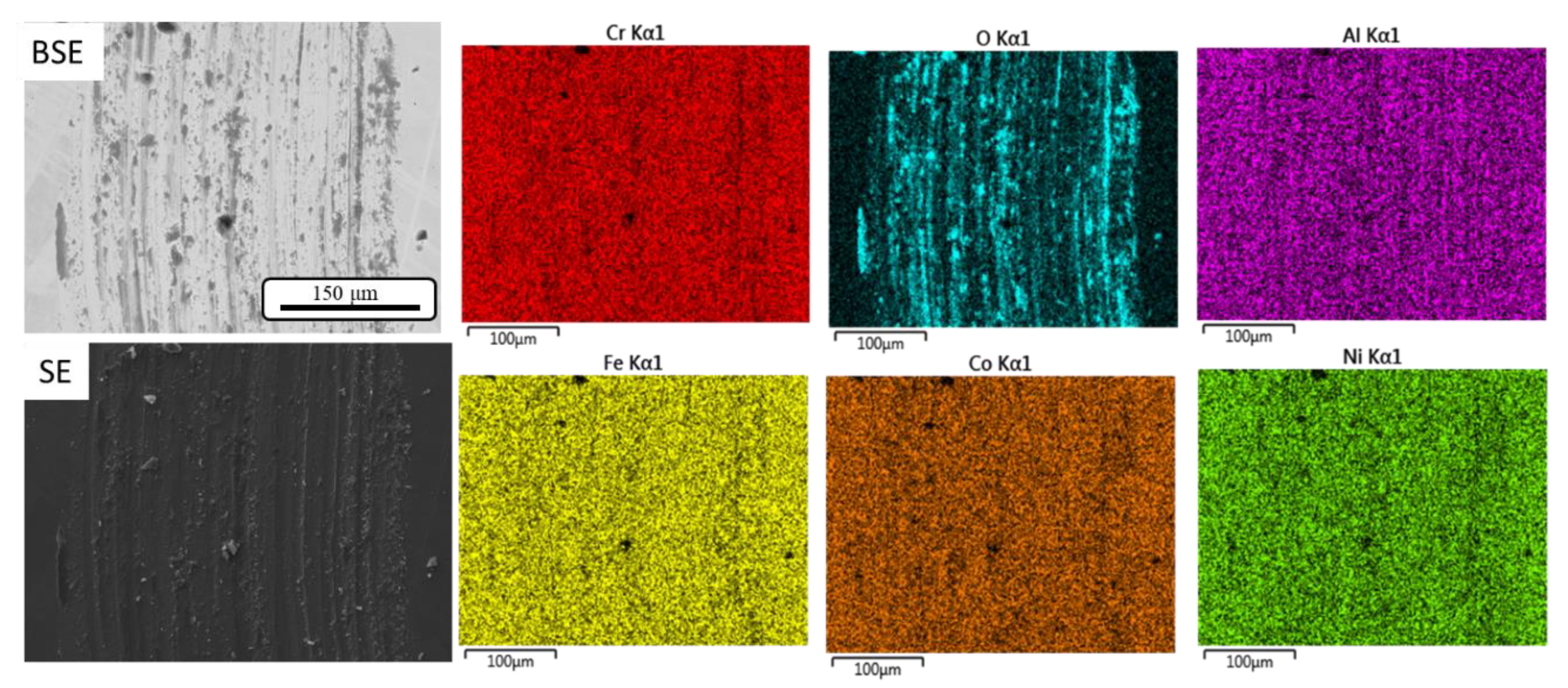
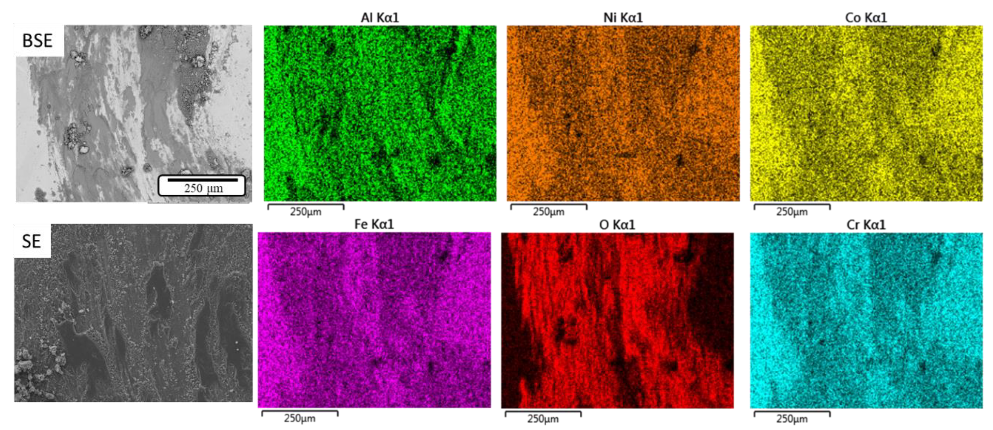
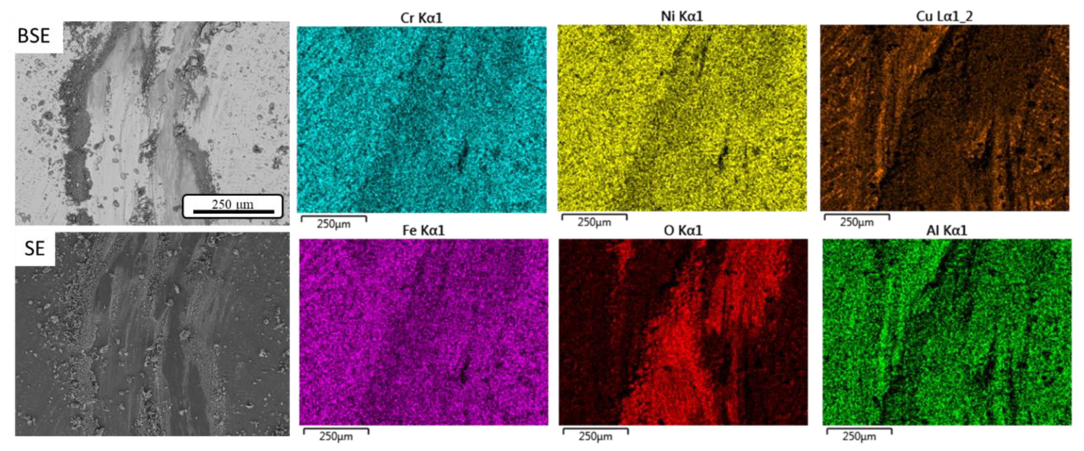
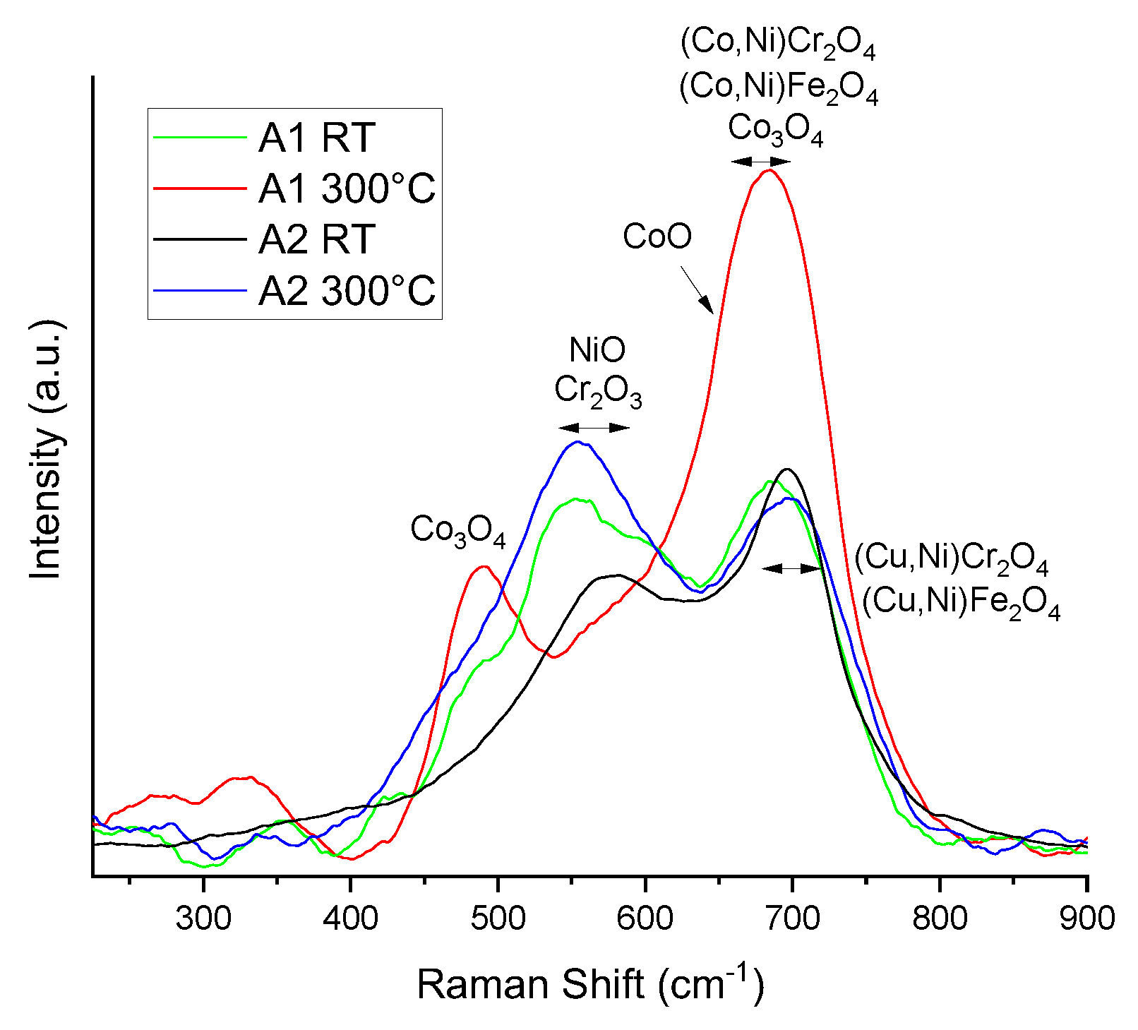
3.4. Friction and Wear Mechanisms

Figure 4 shows representative SEM images and EDS maps of the A1 alloy wear track after RT sliding. The wear track shows signs of abrasive wear, i.e., microabrasion with grooves along the sliding direction. There is also oxidative wear based on the dark features in the BSE images (meaning a higher atomic number contrast) that coincides with the oxygen EDS map in Figure 4. Based on the elemental maps, there is not one particular metal that shows a preference for oxidative wear. This suggests that there is a mixed metal oxide tribofilm on the wear surface. These flattened oxide patches inside the wear track are indicative of a surface fatigue wear mode that results in metallic oxide wear fragments delaminating from the surface. With repeated sliding, the wear fragments can either be ejected from the sliding contact or become entrapped beneath the Si3N4 counterface, with the latter pathway contributing to the formation of micro-grooves by a three-body abrasive wear mode.
Figure 5 shows representative SEM images and EDS maps of the A2 alloy wear track after RT sliding. Similar to the A1 alloy, there is micro-ploughing/micro-grooving inside the wear track, indicating a micro-abrasive wear mode with striations running parallel to the sliding direction and across the entire wear track length. There are also oxidative/surface fatigue wear modes present, although the wear track width is slightly smaller, and there is slightly less micro-abrasion/metal oxide tribofilm covering the wear track. This accounts for the slightly lower RT COF and wear factor values listed in Table 3 for the A2 alloy.
Figure 6 shows SEM images and EDS maps of the A1 alloy wear track after 300 °C sliding. It is evident there is an increased amount of oxidative wear compared to RT sliding for this alloy, based on the BSE image and corresponding oxygen EDS wear map covering almost the entire wear track. Furthermore, it appears that this oxide tribofilm is also a mix of all the metallic elements, based on the EDS maps that do not show a preference for any particular metal oxide phase. Despite the lower COF due to the lower interfacial shear strength oxide tribofilm, the wear track width has increased in size compared to the RT wear track. This is supported by the increased wear factor listed in Table 3, due to thermal softening for this A1 alloy, which is based on the lower hardness value of HV1 = 144. More severe adhesive wear also occurs in the wear track shown by the SEM images in Figure 6, since these wear tracks are covered with a compact tribofilm (often referred to as an oxide glaze layer), indicating a change in wear mechanisms. Abrasive grooves along the sliding direction are still visible on the wear track in areas not covered by the oxidized tribofilm. In addition, there is evidence of fragmented oxide wear debris that further acts similar to abrasive particles to accelerate the wear process, resulting in the high wear factor. Therefore, while the low interfacial shear strength oxide tribofilm provides low COF values, it not protective at this elevated sliding temperature compared to RT sliding.
In contrast, the A2 alloy exhibits increased hardness, up to HV1 = 188 at 300 °C, which results in a slightly smaller wear track, as shown in Figure 7, and thus a smaller frictional area of contact during sliding. Hence, the A2 alloy has the lowest COF of ~0.29 and a slightly lower wear factor of 9.8 × 10⁻⁵ mm3/N·m compared to the A1 alloy at 300 °C, but this is still higher compared to RT sliding. Hardening in the A2 alloy is likely due to the increased amount of Ni resulting in the formation of a NiO scale, although verification would be needed with cross-sectional microscopy and micro-indentation. The wear track shown in Figure 7 exhibits slightly less oxidative wear compared to the A1 alloy, based on the images and EDS oxygen map. In addition, the fragmented oxide wear debris act as micro-abrasive particles, resulting in increased wear. Like the A1 alloy, the low interfacial shear strength oxide tribofilm results in low COF values, but overall does not provide wear protection at this elevated sliding temperature compared to RT sliding. Similarl to other alloys such as the CoCr-based alloy (Haynes 25), at temperatures greater than 200 °C, the friction coefficient is reduced due to the formation of a protective oxide layer, which minimizes the adhesion between the two contacting surfaces [31]. When the temperature becomes greater than 150 °C, the sintering rates of the metal oxide films increase, which leads to the formation of glazes (Co and Cr oxides) that can supply prolonged protection against friction and reduce the friction coefficient [32]. In addition, low unidirectional sliding friction coefficients for Co-based alloys at temperatures greater than 200 °C can be attributed to the formation of thermally stable oxide glazes on the pin surface, which cause low friction and wear [28].
The Si3N4 counterfaces showed some abrasive wear with extruded wear debris at RT, while at 300 °C, the counterfaces exhibited similar features, along with some adhered metal oxide transfer films from the wear tracks. A similar study revealed there is no accumulation of third bodies or transfer films adhered to the Si3N4 balls after RT sliding for HEAs Al0.1CoCrFeNi and CoCrFeMnNi [30]. In order to better determine the tribochemcial oxide phases, Raman spectroscopy was performed inside the four wear tracks shown in Figure 4, Figure 5, Figure 6 and Figure 7. Figure 8 shows representative Raman spectra for the alloys after RT and 300 °C sliding. It is evident there are several oxide phases, both binary oxides and multi-element solid solution oxides, present in both alloys, including CoO, Co3O4, Cr2O3, NiO, and multi-element Cr2O4 and Fe2O4 tribochemical phases. These metal oxides tribochemically form at intermediate and higher temperatures via tribo-sintering the compact oxide tribofilm, which has been shown to lower the friction coefficients [28,33]. These oxide phases are in good agreement with the Raman spectra acquired inside FeCrNi medium-entropy alloy and CoCrFeNi HEA wear tracks, respectively [33,34]. The higher-Ni content A2 alloy at 300 °C exhibited a higher intensity peak of NiO and Cr2O3 in the tribofilm, which could be responsible for its lower friction and wear. Future studies will explore sliding temperatures higher than 300 °C to determine if there are more protective high-temperature oxide phases in both alloy tribofilms that result in low interfacial shear strength for friction reduction, while simultaneously providing low wear. It is possible that at higher sliding temperatures than 300 °C, the thermal softening process is counteracted by the formation of more protective tribochemical oxide phases that act as solid lubricants, thereby lowering friction and wear.

4. Summary and Conclusions

Two FCC single-phase HEAs alloys with different Ni contents and either Co or Cu were studied: Al0.3CoFeCrNi (A1) and Al0.3CuFeCrNi2 (A2). For the A1 alloy with lower Ni content, micro-indentation and sliding wear tests revealed that the hardness decreased, resulting in thermal softening and a higher wear factor during 300 °C sliding. In contrast, the higher Ni content A2 alloy exhibited increasing hardness and subsequently a slightly lower wear factor. Mechanistic wear studies showed this was due to the oxidative wear, with the formation of low interfacial shear strength tribofilms that covered the wear tracks. Raman spectra determined that the A2 alloy at 300 °C exhibits a higher intensity peak of NiO and Cr2O3 in the oxide tribofilm, which is likely responsible for lowering both the COF and wear factor. However, compared to RT sliding, both alloys provide no wear protection during 300 °C sliding, most likely due to thermal softening in the tribofilms. Thus, these single FCC-phase HEAs provide no further benefit to wear resistance at elevated temperatures, with similar implications likely for other such single FCC-phase HEAs. Lastly, these and other single-phase HEAs without hard secondary phases are no better than current bearing steels.

Author Contributions

Conceptualization, D.F.K. and T.W.S.; methodology, D.F.K., M.V.K. and T.W.S.; formal analysis, D.F.K., M.V.K. and T.W.S.; investigation, D.F.K., M.V.K. and T.W.S.; data curation, D.F.K. and M.V.K.; writing—original draft preparation, D.F.K. and T.W.S.; writing—review and editing, D.F.K. and T.W.S.; supervision, T.W.S. All authors have read and agreed to the published version of the manuscript.

Funding

This research received no external funding.

Data Availability Statement

All data generated or analyzed during this study are included in this published article.

Acknowledgments

We thank Bharat Gwalani for providing the two alloys, and the UNT Materials Research Facility (MRF) for access to SEM/EDS and XRD.

Conflicts of Interest

The authors declare no conflict of interest.

References

  1. Yeh, J.W.; Chen, S.K.; Lin, S.J.; Gan, J.Y.; Chin, T.S.; Shun, T.T.; Tsau, C.H.; Chang, S.Y. Nanostructured High-Entropy Alloys with Multiple Principal Elements: Novel Alloy Design Concepts and Outcomes. Adv. Eng. Mater. 2004, 6, 299–303+274. [Google Scholar] [CrossRef]
  2. Cantor, B.; Chang, I.T.H.; Knight, P.; Vincent, A.J.B. Microstructural Development in Equiatomic Multicomponent Alloys. Mater. Sci. Eng. A 2004, 375–377, 213–218. [Google Scholar] [CrossRef]
  3. Klenam, D.; Asumadu, T.; Bodunrin, M.; Vandadi, M.; Bond, T.; Merwe, J.; Van Der Rahbar, N.; Soboyejo, W. Cold Spray Coatings of Complex Concentrated Alloys: Critical Assessment of Milestones, Challenges, and Opportunities. Coatings 2023, 13, 538. [Google Scholar] [CrossRef]
  4. Miracle, D.B.; Senkov, O.N. A Critical Review of High-entropy alloys and Related Concepts. Acta Mater. 2017, 122, 448–511. [Google Scholar] [CrossRef] [Green Version]
  5. Lin, Y.C.; Cho, Y.H. Elucidating the Microstructure and Wear Behavior for Multicomponent Alloy Clad Layers by in Situ Synthesis. Surf. Coatings Technol. 2008, 202, 4666–4672. [Google Scholar] [CrossRef]
  6. Zhang, Y.; Li, R. New Advances in High-Entropy Alloys. Entropy 2020, 22, 1158. [Google Scholar] [CrossRef]
  7. Chuang, M.; Tsai, M.; Wang, W.; Lin, S.; Yeh, J. Microstructure and Wear Behavior of AlxCo1.5CrFeNi1.5Tiy High-Entropy Alloys. Acta Mater. 2011, 59, 6308–6317. [Google Scholar] [CrossRef]
  8. Wang, W.R.; Wang, W.L.; Yeh, J.W. Phases, Microstructure and Mechanical Properties of AlxCoCrFeNi High-Entropy Alloys at Elevated Temperatures. J. Alloys Compd. 2014, 589, 143–152. [Google Scholar] [CrossRef]
  9. Liu, Y.; Xu, Z.; Xu, G.; Chen, H. Influence of Al Addition on the Microstructure and Wear Behavior of Laser Cladding FeCoCrNiAlx High-Entropy Alloy Coatings. Coatings 2023, 13, 426. [Google Scholar] [CrossRef]
  10. Miao, J.; Li, T.; Li, Q.; Chen, X.; Ren, Z.; Lu, Y. Enhanced Surface Properties of the Al0.65CoCrFeNi High-Entropy Alloy via Laser Remelting. Materials 2023, 16, 1085. [Google Scholar] [CrossRef]
  11. Wu, J.M.; Lin, S.J.; Yeh, J.W.; Chen, S.K.; Huang, Y.S.; Chen, H.C. Adhesive Wear Behavior of AlxCoCrCuFeNi High-Entropy Alloys as a Function of Aluminum Content. Wear 2006, 261, 513–519. [Google Scholar] [CrossRef] [Green Version]
  12. Jiang, J.; Chen, P.; Qiu, J.; Sun, W.; Saikov, I.; Shcherbakov, V.; Alymov, M. Microstructural Evolution and Mechanical Properties of AlxCoCrFeNi High-Entropy Alloys under Uniaxial Tension: A Molecular Dynamics Simulations Study. Mater. Today Commun. 2021, 28, 102525. [Google Scholar] [CrossRef]
  13. Shun, T.T.; Du, Y.C. Microstructure and Tensile Behaviors of FCC Al0.3CoCrFeNi High Entropy Alloy. J. Alloys Compd. 2009, 479, 157–160. [Google Scholar] [CrossRef]
  14. Wang, X.; Zhang, Z.; Wang, Z.; Ren, X. Microstructural Evolution and Tensile Properties of Al0.3CoCrFeNi High-Entropy Alloy Associated with B2 Precipitates. Materials 2022, 15, 1215. [Google Scholar] [CrossRef]
  15. Gwalani, B.; Gorsse, S.; Choudhuri, D.; Zheng, Y.; Mishra, R.S.; Banerjee, R. Tensile Yield Strength of a Single Bulk Al0.3CoCrFeNi High Entropy Alloy Can Be Tuned from 160 MPa to 1800 MPa. Scr. Mater. 2019, 162, 18–23. [Google Scholar] [CrossRef]
  16. Jiao, Z.M.; Ma, S.G.; Yuan, G.Z.; Wang, Z.H.; Yang, H.J.; Qiao, J.W. Plastic Deformation of Al0.3CoCrFeNi and AlCoCrFeNi High-Entropy Alloys Under Nanoindentation. J. Mater. Eng. Perform. 2015, 24, 3077–3083. [Google Scholar] [CrossRef]
  17. Kao, Y.F.; Chen, T.J.; Chen, S.K.; Yeh, J.W. Microstructure and Mechanical Property of As-Cast, -Homogenized, and -Deformed AlxCoCrFeNi (0 < x < 2) High-Entropy Alloys. J. Alloys Compd. 2009, 488, 57–64. [Google Scholar] [CrossRef]
  18. Guo, S.; Ng, C.; Lu, J.; Liu, C.T. Effect of Valence Electron Concentration on Stability of Fcc or Bcc Phase in High-entropy alloys. J. Appl. Phys. 2011, 109. [Google Scholar] [CrossRef] [Green Version]
  19. Guo, S.; Ng, C.; Liu, C.T. Anomalous Solidification Microstructures in Co-Free Al XCrCuFeNi2 High-Entropy Alloys. J. Alloys Compd. 2013, 557, 77–81. [Google Scholar] [CrossRef]
  20. Shun, T.T.; Hung, C.H.; Lee, C.F. Formation of Ordered/Disordered Nanoparticles in FCC High-entropy alloys. J. Alloys Compd. 2010, 493, 105–109. [Google Scholar] [CrossRef]
  21. Ng, C.; Guo, S.; Luan, J.; Wang, Q.; Lu, J.; Shi, S.; Liu, C.T. Phase Stability and Tensile Properties of Co-Free Al0.5CrCuFeNi2 High-Entropy Alloys. J. Alloys Compd. 2014, 584, 530–537. [Google Scholar] [CrossRef]
  22. Gwalani, B.; Soni, V.; Choudhuri, D.; Lee, M.; Hwang, J.Y.; Nam, S.J.; Ryu, H.; Hong, S.H.; Banerjee, R. Stability of Ordered L12 and B2 Precipitates in Face Centered Cubic Based High-entropy alloys–Al0.3CoFeCrNi and Al0.3CuFeCrNi2. Scr. Mater. 2016, 123, 130–134. [Google Scholar] [CrossRef]
  23. Guardian, R.; Rosales-Cadena, I.; Diaz-Reyes, C.; Ruiz-Ochoa, J.A. Wear Evaluation of Copper-Nickel-Aluminum Alloys under Extreme Conditions. J. Miner. Mater. Charact. Eng. 2023, 11, 16–26. [Google Scholar] [CrossRef]
  24. Qiu, X.-W.; Liu, C.-G. Microstructure and Properties of Al2CrFeCoCuTiNix High-Entropy Alloys Prepared by Laser Cladding. J. Alloys Compd. 2013, 553, 216–220. [Google Scholar] [CrossRef]
  25. López Ríos, M.; Socorro Perdomo, P.P.; Voiculescu, I.; Geanta, V.; Crăciun, V.; Boerasu, I.; Mirza Rosca, J.C. Effects of Nickel Content on the Microstructure, Microhardness and Corrosion Behavior of High-Entropy AlCoCrFeNix Alloys. Sci. Rep. 2020, 10, 1–11. [Google Scholar] [CrossRef]
  26. Kuo, P.-C.; Chen, S.-Y.; Yu, W.; Okumura, R.; Iikubo, S.; Laksono, A.D.; Yen, Y.-W.; Pasana, A.S. The Effect of Increasing Nickel Content on the Microstructure, Hardness, and Corrosion Resistance of the CuFeTiZrNix High-Entropy Alloys. Materials 2022, 15, 3098. [Google Scholar] [CrossRef]
  27. Torgerson, T.B.; Mantri, S.A.; Banerjee, R.; Scharf, T.W. Room and Elevated Temperature Sliding Wear Behavior and Mechanisms of Additively Manufactured Novel Precipitation Strengthened Metallic Composites. Wear 2019, 426–427, 942–951. [Google Scholar] [CrossRef]
  28. Scharf, T.W.; Prasad, S.V.; Kotula, P.G.; Michael, J.R.; Robino, C.V. Elevated Temperature Tribology of Cobalt and Tantalum-Based Alloys. Wear 2015, 330–331, 199–208. [Google Scholar] [CrossRef] [Green Version]
  29. Gwalani, B.; Ayyagari, A.V.; Choudhuri, D.; Scharf, T.; Mukherjee, S.; Gibson, M.; Banerjee, R. Microstructure and Wear Resistance of an Intermetallic-based Al0.25Ti0.75CoCrFeNi High Entropy Alloy. Mater. Chem. Phys. 2018, 210, 197–206. [Google Scholar] [CrossRef]
  30. Ayyagari, A.; Barthelemy, C.; Gwalani, B.; Banerjee, R.; Scharf, T.W.; Mukherjee, S. Reciprocating Sliding Wear Behavior of High-entropy alloys in Dry and Marine Environments. Mater. Chem. Phys. 2018, 210, 162–169. [Google Scholar] [CrossRef]
  31. Korashy, A.; Attia, H.; Thomson, V.; Oskooei, S. Characterization of Fretting Wear of Cobalt-Based Superalloys at High Temperature for Aero-Engine Combustor Components. Wear 2015, 330–331, 327–337. [Google Scholar] [CrossRef]
  32. Pauschitz, A.; Roy, M.; Franek, F. Mechanisms of Sliding Wear of Metals and Alloys at Elevated Temperatures. Tribol. Int. 2008, 41, 584–602. [Google Scholar] [CrossRef]
  33. Fu, A.; Xie, Z.; He, W.; Cao, Y. Effect of Temperature on Tribological Behavior of FeCrNi Medium Entropy Alloy. Metals 2023, 13, 282. [Google Scholar] [CrossRef]
  34. Zhang, A.; Han, J.; Su, B.; Li, P.; Meng, J. Microstructure, Mechanical Properties and Tribological Performance of CoCrFeNi High Entropy Alloy Matrix Self-Lubricating Composite. Mater. Des. 2017, 114, 253–263. [Google Scholar] [CrossRef]
Figure 1. XRD patterns of A1 and A2 alloys showing FCC reflections.
Crystals 13 00609 g001
Figure 2. SEM images of the A1 (left) and A2 (right) alloys.
Crystals 13 00609 g002
Figure 3. Representative cross-sectional wear track depths and widths of A1 and A2 alloys after RT and 300 °C sliding.
Crystals 13 00609 g003
Figure 4. BSE and SE images and corresponding EDS elemental maps of the A1 alloy wear track after RT sliding.
Crystals 13 00609 g004
Figure 5. BSE and SE images and corresponding EDS elemental maps of the A2 alloy wear track after RT sliding.
Crystals 13 00609 g005
Figure 6. BSE and SE images and corresponding EDS elemental maps of the A1 alloy wear track after 300 °C sliding.
Crystals 13 00609 g006
Figure 7. BSE and SE images and corresponding EDS elemental maps of the A2 alloy wear track after 300 °C sliding.
Crystals 13 00609 g007
Figure 8. Raman spectra acquired inside A1 alloy and A2 alloy wear tracks after RT and 300 °C sliding.
Crystals 13 00609 g008
Table 1. Chemical composition (in at%) of A1 and A2 alloys.
AlCo/CuFeCrNi
A16.6422.4022.5222.9725.47
A25.6919.4717.6718.5238.65
Table 2. Average microhardness (HV1) values and standard deviations of A1 and A2 alloys at RT and 300 °C.
RT300 °C
A1168 ± 3144 ± 10
A2164 ± 4188 ± 18
Table 3. Average steady-state COF values and wear factors (mm3/N·m) with standard deviations of A1 and A2 alloys at RT and 300 °C.
RT300 °CRT300 °C
COFWear factors
A10.84 ± 0.060.54 ± 0.046.6 ± 0.8 × 10−51.2 ± 0.3 × 10⁻⁴
A20.78 ± 0.060.29 ± 0.055.3 ± 1.1 × 10−59.8 ± 0.4 × 10⁻⁵
Disclaimer/Publisher’s Note: The statements, opinions and data contained in all publications are solely those of the individual author(s) and contributor(s) and not of MDPI and/or the editor(s). MDPI and/or the editor(s) disclaim responsibility for any injury to people or property resulting from any ideas, methods, instructions or products referred to in the content.

