1. Introduction
Optical systems in which the components include loss and gain are non-Hermitian [
1,
2]. The imaginary terms of refractive indices of materials in non-Hermitian optical systems are nonzero. Furthermore, the reflection spectra of light waves are not identical for beams incident from two opposite directions, as the imaginary term of the refractive index of systems is asymmetric to the central point [
3,
4]. For special parity-time−symmetric (PT−symmetric) structures, the zero points of right and left reflectance, also called exceptional points (EPs), do not coalesce [
5,
6]. The PT symmetry in optics demands the refractive index satisfy
n (
r) =
n* (−
r), in which the symbol
r represents the spatial position coordinate. The left reflectance in a spectrum may be zero with a given incident wavelength in PT−symmetric systems, while the right reflection can be nonzero with the same incident wavelength, which can be utilized for optically unidirectional invisibility [
7]. Furthermore, anti-parity-time (APT) symmetry systems are proposed based on PT symmetry [
8,
9].
The refractive index of APT−symmetry structures can be denoted by
n (
r) = −
n* (−
r) [
8,
9]. The refractive index is further rewritten as
n(
z) =
nr(
z) +
i∗
ni(
z). Then, the APT symmetry condition could be separated into two equations, viz.
ni(
z) =
ni(−
z) and
nr(
z) = −
nr(−
z). The imaginary term of the refractive index function is even symmetric to the central point, and the real term of the refractive index function is odd symmetric. In optical systems, if the imaginary item of the refractive index is positive, it represents the optical loss of materials. As systems are constructed by semiconductors, such as silicon (Si) and gallium phosphide (GaP), the optical loss could be regulated by ion doping. On the other hand, optical gain in systems is represented by a negative imaginary term of the material refractive index. SiO
2 and LiNbO
3 can be utilized for gain materials, and optical gain can be realized through nonlinear two-wave mixing [
10].
For a transmitted resonant mode, it corresponds to a transmission peak in the spectrum, so the transmittance of resonance is the maximum in the transmission spectrum, and the corresponding reflectance is the minimum in the reflection spectrum. In some cases, the reflectance is nearly equal to zero at the transmission mode. Since giant Goos–Hänchen (GH) shifts of reflected beams can be achieved around the zero-reflected point [
2,
11], it should promote the reflectance of the resonant mode to observe the reflected light in experiments. However, the reflection wavelength of the resonance may change as the reflectance of light is increased. Even if the light waves are bidirectionally invisible in the system, the invisible wavelength of the right and left reflection zero points may be regulated by the gain/loss in materials [
12], but the direction-dependent reflectance of light waves can not be modulated flexibly with a given incident light wavelength.
Optical fractal resonant states, generally realized in aperiodic structures, can induce numerous nonzero reflection points of light [
13,
14,
15]. The quasi-periodic dielectrics multilayers are fractal structures and include plenty of defects [
14,
15]. Light waves are reflected forward and backward in the defective cavities to form optical fractal states which have the maximum transmittance and the minimum reflectance [
16]. The optical gain and loss in materials can also be utilized to tune the reflectance and transmittance of light beams in systems [
17]. Therefore, it inspires us to combine the quasi-periodic dielectric multilayers with APT symmetry to regulate the reflection anisotropy and explore some fascinating non-Hermitian properties, such as optical exceptional points (EPs) and lasing points.
In this study, dielectric slabs are picked out to form Cantor multilayers. Cantor fractal multilayers are aperiodic, and the refractive index of the whole system satisfies APT symmetry. Optical fractal resonant states in the APT-symmetric system are explored, and the effect of APT symmetry on the fractal resonances is investigated as well. We then demonstrate the reflection anisotropy of light waves and discuss the suppression and enhancement of reflected beams around EPs. Finally, multiple EPs are presented in the parametric space composed of the loss coefficient and the normalized frequency. This study has applications in tunable optical reflectors.
2. APT−Symmetric Cantor Multilayers
Cantor multilayers follow the substitution law:
S0 = H,
S1 = HLH,
S2 = HLHLLLHLH, ……,
SN =
SN−1(LLL)
N−1SN−1, ……, where
N (
N = 0, 1, 2, 3, ……) is the sequence generation number.
SN is utilized to express the
N-th term of the Cantor sequence [
18].
Figure 1 provides the Cantor dielectric multilayers, in which the refractive index is anti-parity-time−symmetric (APT−symmetric) to the zero point of the
Z-axis. Along the horizontal direction, four dielectric slabs, H, H
’, L and L
’, arrange alternatively. The letters H, H
’, L and L
’, respectively, represent four homogenous dielectric slabs. For dielectric slab H, the host material is Si. The refractive index of dielectric H is provided by
nH = 3.6 +
i*0.01
q and
q is called the loss coefficient of materials. For dielectric slab L, the host material is GaP. The refractive index of dielectric L is provided by
nL = 3.0 +
i*0.01
q accordingly. The thicknesses of slabs H and L are set as
dH = 0.05 μm and
dL = 0.1 μm, respectively. In the same way, we choose GaP for the slab H
’ as well, with the refractive index
nH’ = 3.0 +
i*0.01
q. The thickness of slab H
’ is
dH′ = 0.05 μm.Slab L
’ is Si, and its refractive index is
nL′ = 3.6 +
i*0.01
q. The corresponding thickness is set as
dL′ = 0.1 μm. The refractive indices of the four types of dielectric slabs can be rewritten as
nH = 3.3 + 0.3 +
i*0.01
q,
nH′ = 3.3 − 0.3 +
i*0.01
q,
nL = 3.3 − 0.3 +
i*0.01
q and
nL’ = 3.3 + 0.3 +
i*0.01
q, respectively. Consequently, we normalize the refractive indices in the expressions of
n’H =
nH − 3.3 = 0.3 +
i*0.01
q,
n’H’ =
nH’ − 3.3 = −0.3 +
i*0.01
q,
n’L =
nL − 3.3 = −0.3 +
i*0.01
q and
n’L′ =
nL′ − 3.3 = 0.3 +
i*0.01
q. The normalized refractive indices are obviously anti-parity-time−symmetric around the center point. The APT-symmetric condition demands the refractive index meet the equation
n(
z) = −
n*(−
z), which is further divided into two expressions:
nr(
z) = −
nr(−
z) and
ni(
z) =
ni(−
z) [
19]. In other words, the imaginary term of the refractive index is even symmetric to the center point, while the real term is odd symmetric. The values of loss coefficient
q are the same for Si and GaP in our simulation. We referred to the gain/loss factors of different dielectrics set in PT-symmetric or APT-symmetric systems for simplicity [
20,
21,
22].
The optical loss in materials is denoted by a positive imaginary term of the refractive index, while the optical gain is represented by a negative imaginary term of the refractive index. Optical gain in dielectrics could be achieved by nonlinear wave mixing, and optical loss in materials can be modulated by chemical doping. Specifically, Bi ions are doped to enhance the photorefractive properties of Sn
2P
2S
6 crystals and the two-beam coupling gain coefficient increases [
23]. Furthermore, two-wave mixing based on Fe-doped LiNbO
3 could also provide optical gain experimentally. Of which the optical two-wave mixing gain is proportional to the concentration of Fe
3+ centers, while loss arises from the optical excitation of electrons from Fe
2+ centers to the conduction band [
10].
The whole system can also be denoted briefly by HLHLLLHLHH’L’H’L’L’L’H’L’H’. The central symmetric system is constituted by two S2 Cantor dielectric multilayers, where the subscript represents the sequence generator number N = 2. Therefore, one of the Cantor dielectric multilayers S2 can be expressed as HLHLLLHLH, and the other Cantor dielectric multilayers of S2 are denoted by H’L’H’L’L’L’H’L’H’. The whole structure is symmetric to the center, while the refractive index is subtly modulated to satisfy the APT symmetry condition.
As a light wave is an incident in the APT-symmetric multilayers in the left, we, respectively, denote the reflected, transmitted and incident light beams by Irf, Itf and Iif. In the same way, the corresponding reflected, transmitted and incident light beams are, respectively, provided by Irb, Itb and Iib for light waves incident in the right. The included angle between the incident light beam and the horizontal direction is defined as the incident angle, denoted by θ. Here, we set the incident angle as θ = 0 for normal incidence.
We only focus on the influence of optical loss in materials on the non-Hermitian properties in APT-symmetric systems, so the parameter q in passive systems is defined as the loss coefficient in the following investigation.
3. Unidirectional Reflection Enhancement and Suppression
Cantor photonic multilayers are quasi-periodic and can support a photonic bandgap [
18]. We share the concept of photonic bandgap parameter ω
gap = 4ω
0arcsin | [Re(
nH) − Re(
nL)]/[Re(
nH) + Re(
nL)] |
2/π from a characteristic definition in periodic photonic crystals to normalize the light wave frequency [
24]. The symbol ω = 2πc/λ is the angular frequency of the incident light wave. The letter ω
0 = 2πc/λ
0 is the central angular frequency of the light wave. We set the central wavelength as a given value λ
0 = 0.85 μm. As a light wave illuminates normally into the APT-symmetric Cantor dielectric multilayers from the left or right,
Figure 2a demonstrates the transmission and reflection spectra for the lossless dielectrics, viz. the corresponding value of the loss coefficient is
q = 0. The transverse coordinate of (ω − ω
0)/ω
gap is the normalized angular frequency. The letter c is the speed of light in free space. The forward transmission matrix method (FTMM,
File S1) is utilized to derive the transmission and reflection properties in the non-Hermitian systems [
25]. The letter
T represents the transmittance of light waves, while the reflectance is denoted by
R. Light beams can be incident from the right or left. For lossless dielectrics, the transmittance and reflectance are independent of the normally incident directions of lights, such as incidence from the left or from the right.
One can see that there are seven peaks arising in the transmission spectrum between the normalized frequency interval of [−5, 5] for the light waves normally incident from the right or left. There are three transmission peaks denoted by black stars (✩) and P1, P2 and P3, respectively. The corresponding values of transmittance at the three peaks are orderly provided by T = 0.9454, 0.9746 and 0.6608. Their central frequency is given by (ω − ω0)/ωgap = −1.3867, 1.4767 and 4.2633, respectively. The transmittance at the other peaks in the transmission spectrum is T = 1, and the corresponding central frequencies are provided by (ω − ω0)/ωgap = −4.3033, −2.86, −0.03 and 2.94, respectively. The transmittance at the star peaks is obviously lower than the value at the other transmission peaks in lossless systems. In the following, it can be found that some significant phenomena may be induced in this concerned frequency interval around the transmission peaks by changing the optical loss in materials.
There are seven valleys in the reflection spectrum for the light waves incident from the right or left. The corresponding dips of reflectance are almost at the transmission peaks. Around the star symbols, the values at the reflection valleys are R = 0.0546, 0.0254 and 0.3392 at (ω − ω0)/ωgap = −1.3867, 1.4767 and 4.2633, respectively. At the other valleys, the minimum values of reflectance are all equal to R = 0.
For passive systems, the left and right reflection coefficients are not coincident with each other. One can also express the reflection coefficient from the left as
rf = |
rf|exp(
iφrf), in which
φrf represents the complex phase of the reflection coefficient. The corresponding reflection coefficient from the right is expressed as
rb = |
rb|exp(
iφrb), and the transmission coefficient is denoted by
t = |
t|exp(
iφt). For lossless systems, the reflection coefficients from the left and right are coincident, so they can be written as
r = |
r|exp(
iφr). The complex phase of the transmission and reflection coefficients change with the normalized frequency, which is shown in
Figure 2b. At the transmitted peaks, there is an abrupt change in the transmission coefficient phase as the normalized frequency increases. The phase variations at the step points, corresponding to the second, fourth and sixth transmission peaks, are all π in the transmission coefficient phase curve. The slope of the complex phase curve is negative around the first and seventh transmission peaks, while the slope is positive around the other peaks. Since the lateral and horizontal shifts of transmitted and reflected light beams are proportional to the phase curve slope of the transmission and reflection coefficients, giant Goos–Hänchen (GH) shifts or Imbert–Fedorov (IF) shifts may be achieved in this system [
26].
As a light wave impinges on this structure,
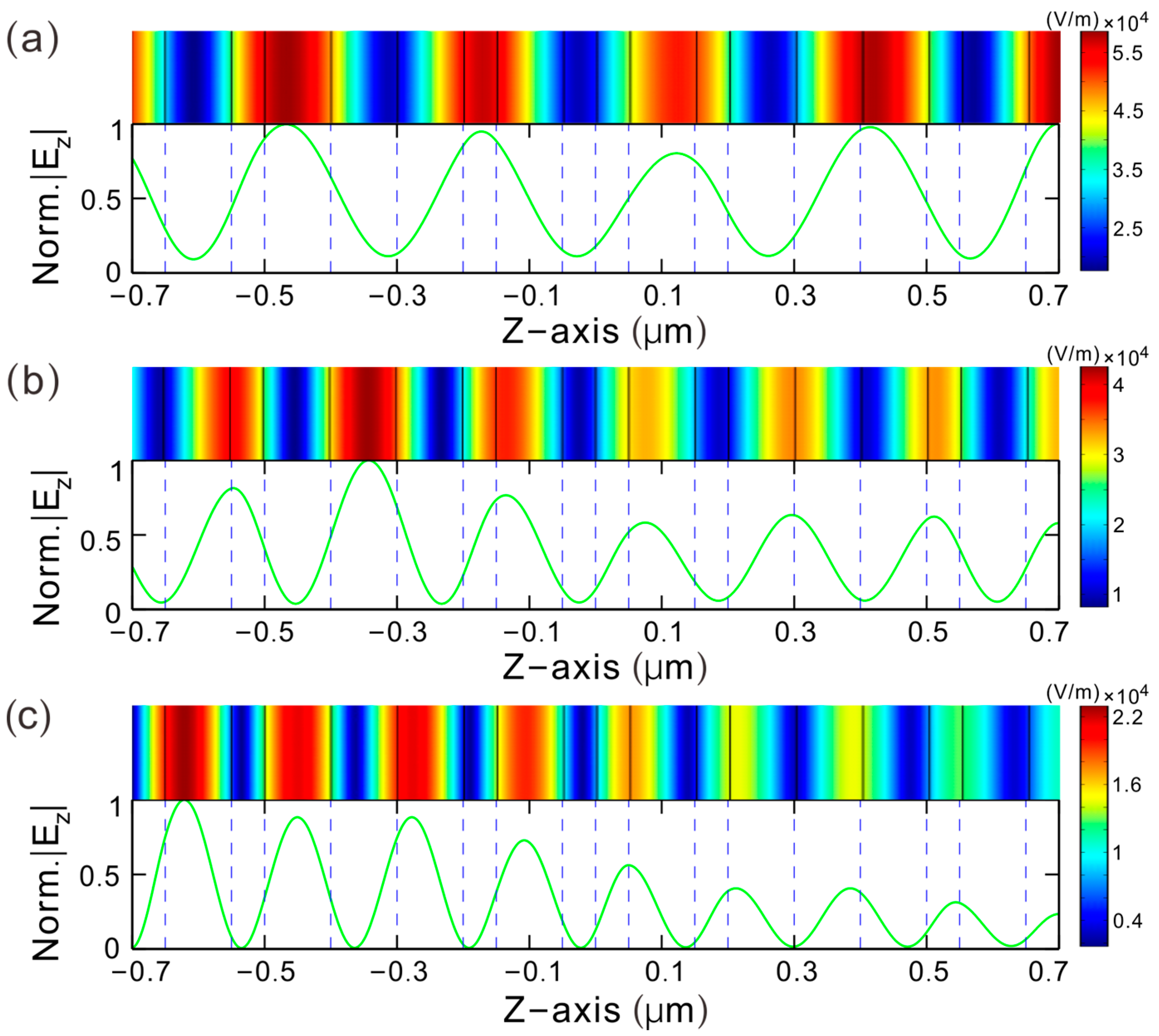
Figure 3a demonstrates the electric field distribution of the third resonant state, denoted by P
1 in
Figure 2a. The corresponding incident wavelength of light is λ = 1.8468 μm. The intensity distribution of the Z-component electric field is derived by the inverse transmission matrix method (ITMM) [
27] and the finite-different time-domain (FDTD) method. The simulating results from the two methods are consistent, and hence the conclusions are reliable. One can see that the intensity of the electric field is not symmetric around the center, which is viewed as the optical fractal state. We also provide the distribution diagram of the electric field of the fifth resonant state, which is denoted by P
2 in
Figure 2a, as shown in
Figure 3b. For the seventh resonant state, denoted by P
3 in
Figure 2a, the electric field distribution is provided in
Figure 3c. The distribution intensities are asymmetric to the central point, and they are also contributed to the optical fractal resonances.
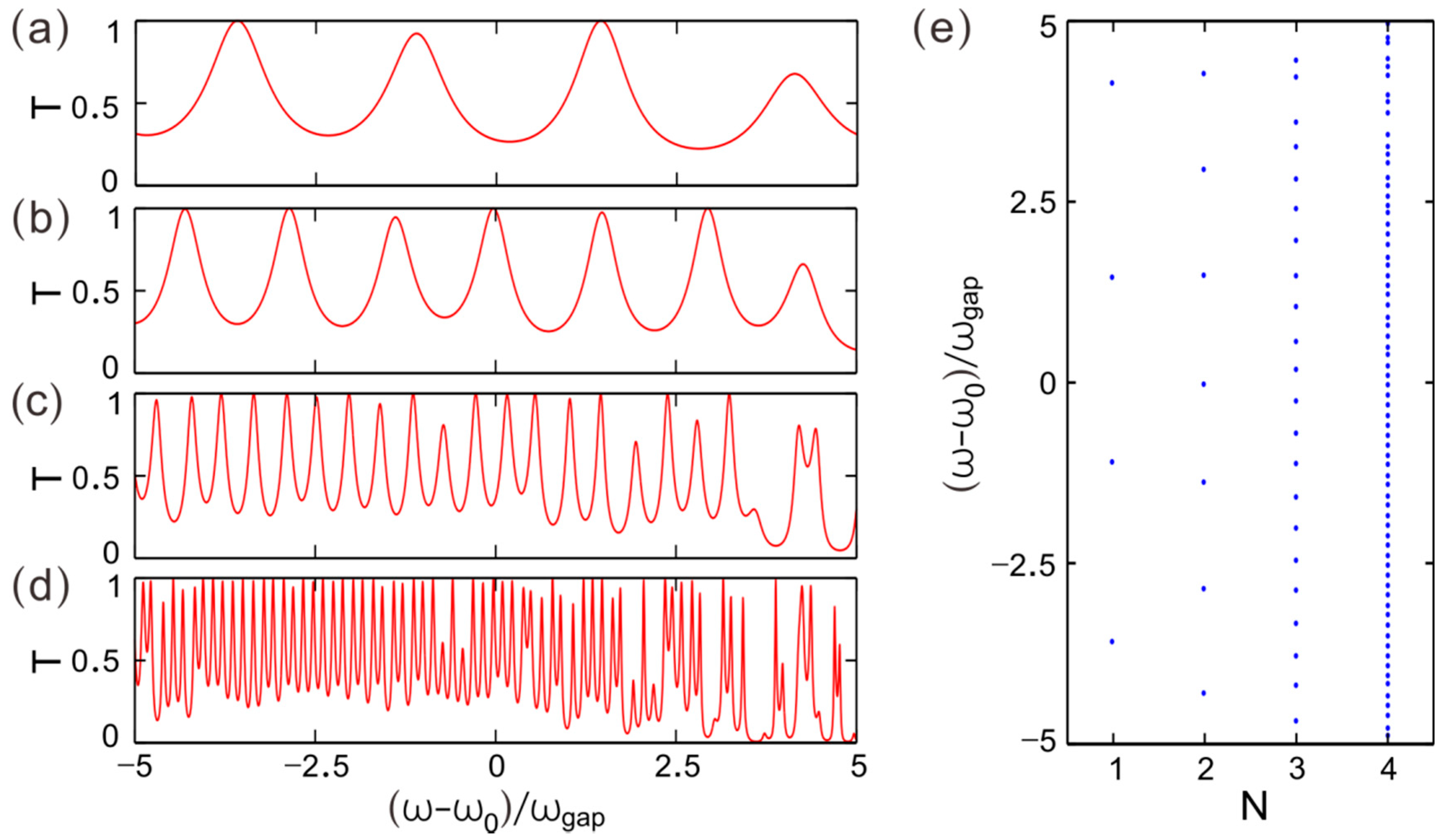
The Cantor multilayers have a self-similarity effect in the transmission spectra as the sequence generation number
N increases. We set the loss coefficient as
q = 0. For light beams incident normally from the left or right,
Figure 4a provides the transmission spectrum by changing the light wave frequency for
N = 1. In the range of normalized frequency [−5, 5], there are four transmission peaks which are called optical fractal resonant states. By increasing the generation number, the defects in Cantor multilayers increase as well, so more resonances may be induced in the fractal systems.
Figure 4b–d provide the transmission spectra for
N = 2, 3 and 4, respectively. The optical fractal states quantities are 7, 22 and 70 in the range of (ω − ω
0)/ω
gap = [−5, 5] accordingly. It is obvious that the number of resonant states increases with the generation number of the Cantor sequence, which is called the self-similarity effect, viz. optical fractal.
Figure 4e shows the position of each optical fractal state in the normalized frequency coordinate axis. One can see that the resonant states split exponentially as the generation number increases.
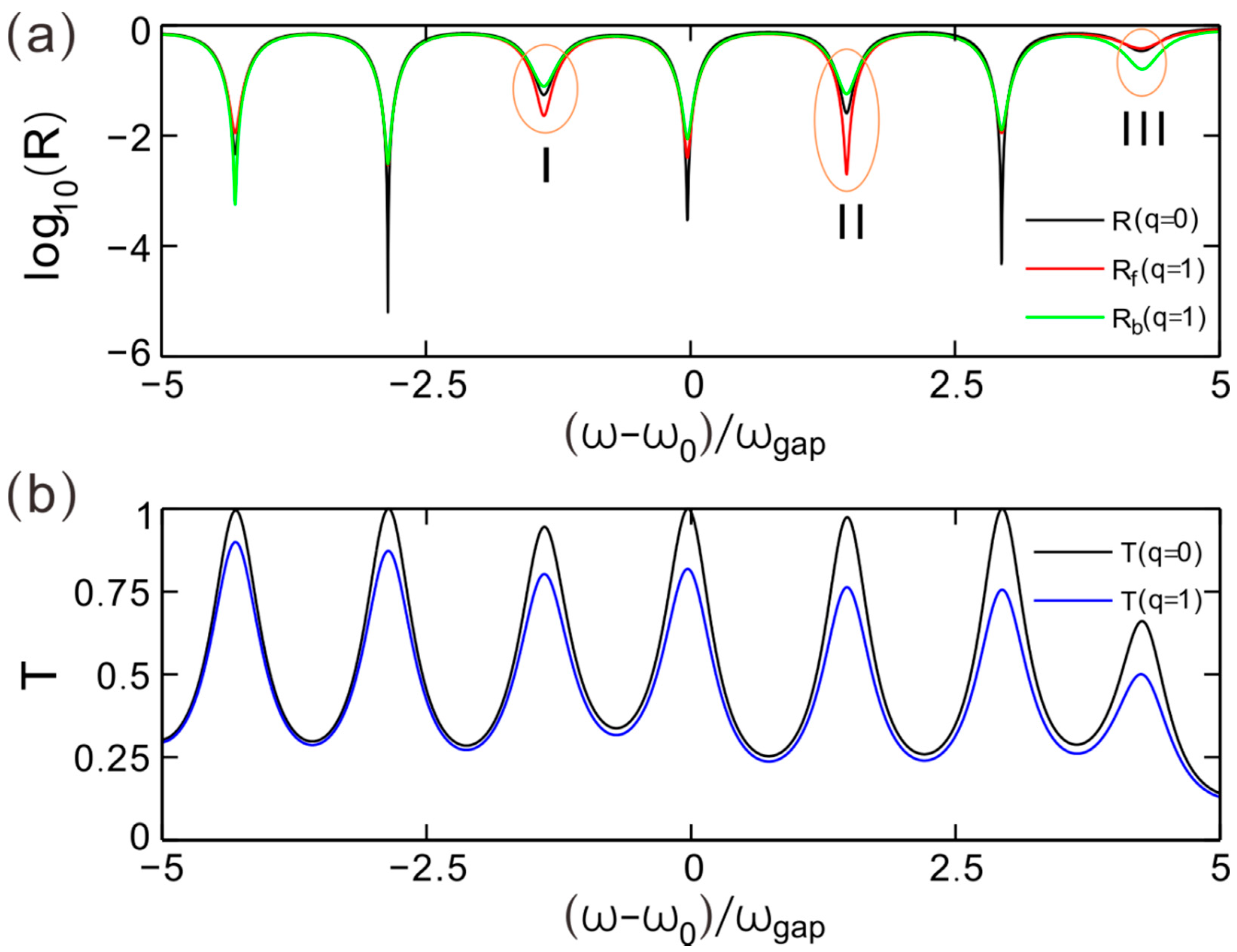
Figure 5a provides the reflection spectra of light beams incident from the left and right for
q = 1. The symbol of
R represents the transmittance of a light wave for
q = 0, while the symbols
Rf and
Rb, respectively, represent the reflectance incident from the left and right for
q ≠ 0. The operation log
10(
R) means taking the logarithm of
R. One can see that the left and right reflection spectra of light waves are not coincident with each other for
q = 1. Furthermore, the two reflection spectra for
q = 1 are different from the reflection spectrum for
q = 0 as well. Especially around the signs of I and II, viz. the two valleys near the center, compared with the reflectance
Rq=0 for
q = 0, the reflectance
Rfq=1 for
q = 1 has been enhanced, while the reflectance
Rbq=1 for
q = 1 has been suppressed.
Figure 5b provides the transmittance of light beams for
q = 0 and 1. One can see that the numbers of transmission peaks in these two spectra are equal. However, the corresponding peak transmittance for
q = 1 is lower than the maximum transmittance for
q = 0. The optical loss in materials decreases the transmitted intensity of light by turning up the value of the loss coefficient. To demonstrate the dependence of enhancement and suppression on the optical loss, we focus on the reflection region near the sign of II, neighboring the center, in the spectra in
Figure 5a.
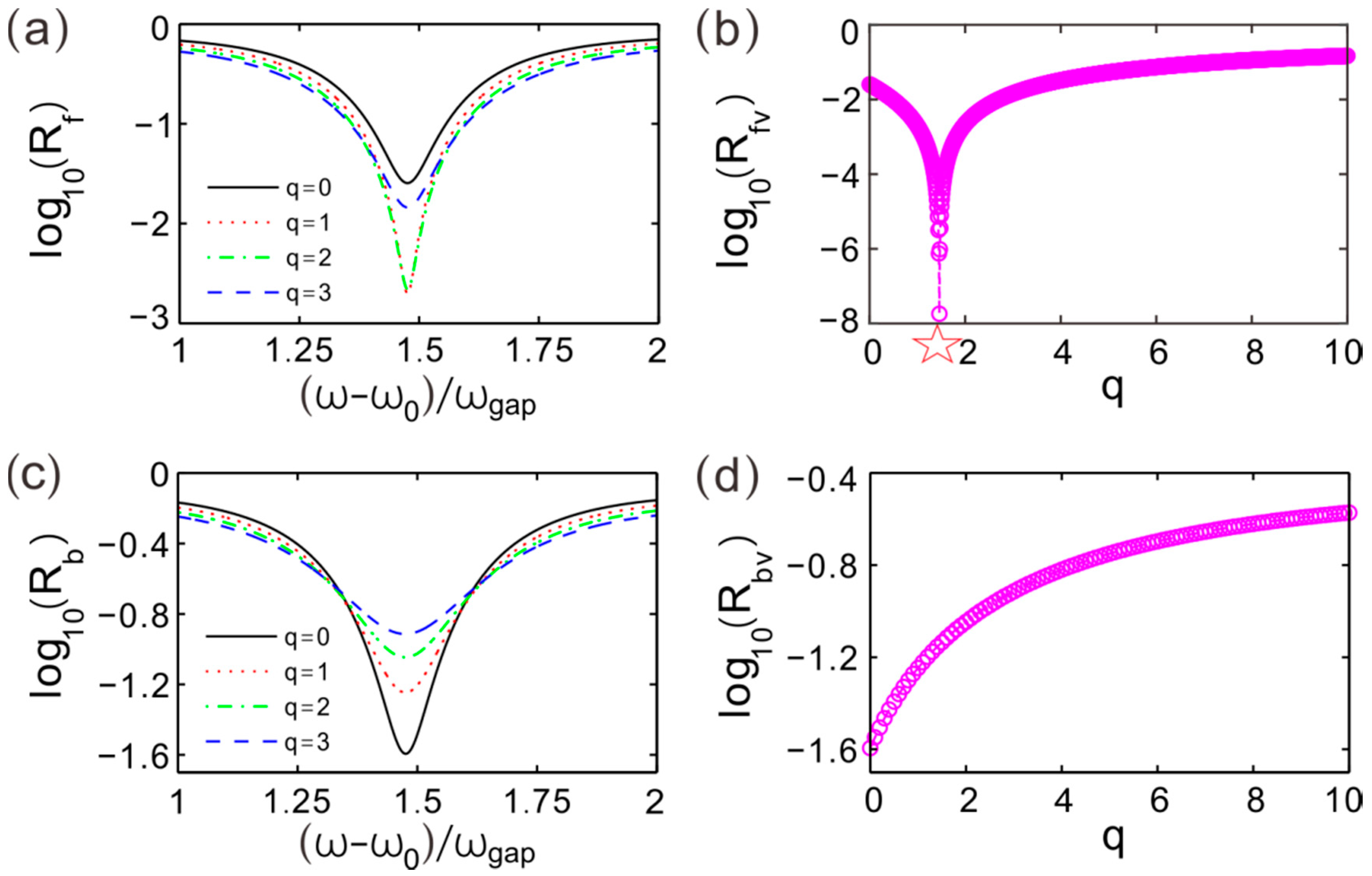
Figure 6a provides the reflection spectra around the valley around the sign of II for different values of the optical loss. There are four given values of loss coefficient
q = 0, 1, 2 and 3. The values of reflectance at the valleys for
q = 1, 2 are lower than that for
q = 0. Therefore, the reflection can be suppressed by turning up the value of
q. However, one can find that the valley reflection value for
q = 1 is equal to that for
q = 3. This phenomenon manifests that singular optical characteristics may exist in the range of
q = [
1,
3].
Figure 6b describes the value at the reflection valley II changing with the optical loss coefficient
q. It demonstrates that the reflectance decreases with the increase in
q, and then there is a dip that appears in the reflectance curve. In our simulation accuracy, the minimum reflectance is provided by log
10(
Rfv) = −7.57 for
q = 1.459. The minimum of
Rfv is denoted by a red star (✩). The minimum reflectance can be further decreased by improving the simulation accuracy accordingly, so the minimum reflectance point can be viewed as the zero point of reflection. Then, increasing the value of
q, the reflectance of light waves changes as well, but the value increases slowly and tends to be constant.
Figure 6c provides the reflectance changing with the normalized frequency for different values of loss coefficient around the reflection valley II. A light wave is an incident from the right. As the light frequency approaches the corresponding value at the valley, the reflection spectrum elevates on the whole by turning up the parameter
q. The reflection value at the valley is denoted by
Rbv.
Figure 6d shows the reflectance at the valley in
Figure 6c changing with the optical loss coefficient. It shows that the reflectance is increasingly proportional to
q. This effect presents that the unidirectional reflection of light waves could be enhanced by modulating the optical loss in dielectrics.
For different values of
q, the transmission spectra are provided in
Figure 7a around the reflection valley II, as shown in
Figure 5a. There is a peak in each transmission spectrum. Light waves can be incident from the right and left. The transmission spectra are coincident. The corresponding frequency at the transmission peaks is exactly equal to these values at the reflection valleys in
Figure 6a.
The resonances of these transmission peaks gradually weaken as the loss coefficient increases. The peak value of transmittance varying with the loss coefficient is demonstrated in
Figure 7b. The transmittance at these peaks is denoted by
Tp, and one can see that the resonance is suppressed by turning up the optical loss. The maximum of transmittance decreases with the increase in
q. Greater optical loss may induce lower transmitted intensity of light accordingly.
To improve the numerical simulating accuracy,
Figure 8a presents the reflectance of light waves by scanning the normalized frequency and the loss coefficient. There is a reflection minimum in the parameter space. The reflectance is log
10(
Rf) = −7.57 at this valley point of [
q = 1.459, (ω − ω
0)/ω
gap = 1.467], so the reflected intensity of light at this minimum can be viewed as
Rf = 0 strictly with a higher simulation accuracy. The APT-symmetric system is non-Hermitian, so the minimum reflection point in the parameter is actually an exceptional point (EP) of non-Hermitian systems.
To represent the EP further,
Figure 8b provides the complex phase of the reflection coefficient changing with the normalized frequency. Light waves are incident from the left and right, respectively. The given loss coefficient is
q = 1.459, which is exactly equal to the value at the EP in the above parameter space, as shown in
Figure 8a. It shows that there is an upward step change in the complex phase at (ω – ω
0)/ω
gap = 1.467. The phase jump is
Δφrf = π for the light wave incident from the left, while for a light beam incident from the right, the phase changes with the normalized frequency continuously by ignoring the meaningless
Δφrb = 2π. For the left incident light wave, the zero point of reflectance at the EP determines the π phase uncertainty. The reflection coefficient is
r(
ωEP) = 0 at EP. The left limit of the reflection coefficient at EP is
r(
ωEP−) < 0, and the right limit is
r(
ωEP+) > 0. As the reflection coefficient is denoted by
r = |
r|exp(
iφr), the phase difference of the right and left limits for the reflection coefficient is
Δφr =
φr(
ωEP+) −
φr(
ωEP−)= π. Therefore, the phase of reflection coefficient
φr(
ωEP) is uncertain at EP. The π variation at the step point in the reflection coefficient phase is a typical characteristic of EPs, which is generally utilized to confirm EPs in non-Hermitian systems.
Furthermore,
Figure 8c,d provides another method to confirm EPs in APT−symmetric systems, in which the imaginary and real terms of eigenvalues of the scattering matrix. Here, the scattering matrix in the APT-symmetric Cantor multilayers is defined as
Scat = [
t rf;
rb t], which can be viewed as the counterpart of Hamiltonian in quantum systems [
22,
28]. The eigenvalues of the
Scat-matrix are λ
1,2 =
t ± (
rfrb)
1/2, and the eigenvectors are provided by (
rf1/2, ±
rb1/2). At (
rfrb)
1/2 = 0, the eigenvectors can degenerate, and the eigenvalues coalesce, which is EP’s conception of eigenvalues. In other words, one can search for EP in parameter space under the condition of
rf or
rb = 0. One can see that, by changing the normalized frequency, the curves of imaginary terms of eigenvalues cross around EP, while for the real terms of eigenvalues, the corresponding curves present the peculiarity of anti-cross near EP. This property further approves the EP of eigenvalues in the parameter space.
The optical fractal effect may have a significant influence on EPs in Cantor APT-symmetric multilayers.
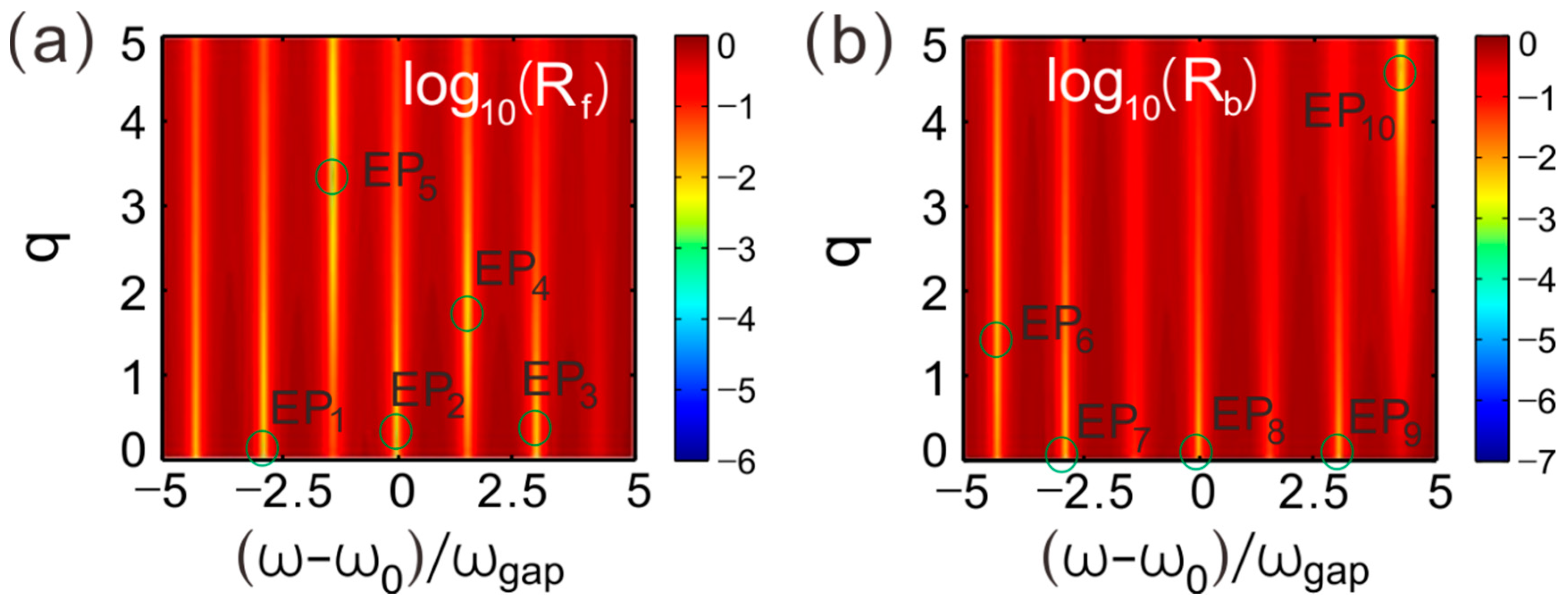
Figure 9a,b provides the transmittance of light waves incident from the left and right, respectively. The parameter space is composed by the loss coefficient and normalized frequency. We have taken the logarithm operation of the transmittance
T of light beams. One can see that, for the left incident light waves, there are five EPs in the interested area of the parameter space, denoted by EP
1, EP
2, EP
3, EP
4 and EP
5, respectively, while for the right incident light beams, there are also five EPs arising in the parameter space, and we denote them by EP
6, EP
7, EP
8, EP
9 and EP
10, respectively.
EPs can also be achieved at these frequencies of the first and the last peaks, as shown in
Figure 5a. We have provided the corresponding EPs in
Figure 9b, respectively, denoted by EP
6 and EP
10. The position coordinates of EP
6 in parameter space are [
q = 1.5802, (
ω −
ω0)/
ωgap = −4.3032], and EP
10 is local at [
q = 4.6652, (
ω −
ω0)/
ωgap = 4.2761].
All of the EPs are labeled with red circles to highlight their positions in the parameter space. The phenomenon demonstrates that multiple EPs may be realized by increasing the generation number
N of the Cantor sequence in APT-symmetric multilayers. These EPs result from optical fractal resonances. Resonant cavities in the aperiodic photonic multilayers increase exponentially as
N increases. The multiple EPs are finally induced by the numerous resonant cavities. Even though it shows a single EP can be induced in the APT-symmetric periodic photonic crystals [
29], our study provides a scheme to achieve multiple EPs in fractal structures, which can be utilized for multiple wavelengths optical reflectors and suppressors.
Since the refractive indices of materials can be regulated by iron doping, we have set the values to remain constant as the incident light wavelength changes. It is a one-to-one correspondence between the normalized frequency and wavelength, so the simulation is still valid by tuning the wavelength. The thickness of each dielectric slab remains unchanged. Consequently, the APT symmetry of Cantor dielectric multilayers could also be satisfied when the wavelength of incident light varies.
The two optical fractal resonances of P
1 and P
3, as shown in
Figure 2a, can also induce Eps. EP
5, presented in
Figure 9a, arises from the fractal resonance of P
1. EP
5 in parameter space is located at [
q = 3.3438, (
ω −
ω0)/
ωgap = −1.3845]. EP
10 originates from the fractal resonance of P
3. The reflection valley I in
Figure 5a corresponds to the transmission peak P
1 in
Figure 2a, and the reflection valley III corresponds to the transmission peak P
3. There is a valley in each reflection spectrum around the frequency of EP. In particular, the valley reflectance for the left incident light is minimum as the loss factor
q = 3.3438 is equal to the corresponding value of EP
5, while the valley reflectance for the right incident light is minimum as the loss factor
q = 4.6652 equates to the corresponding value of EP
10. Therefore, unidirectional suppression and enhancement of reflection can also result from two optical fractal resonances, P
1 and P
3.


