Article

On the Efficient Particle Dispersion and Transfer in the Fabrication of SiC-Particle-Reinforced Aluminum Matrix Composite

1
Department of Materials Processing and Control Engineering, School of Materials Science and Engineering, University of Science and Technology Beijing, Xueyuan Road 30, Haidian District, Beijing 100083, China
2
China Academy of Machinery Sciences and Technology (Jiangle) Institute of Semi-Solid Metal Technology, Huancheng East Road 22, Jiangle County, Sanming 353300, China
3
Department of Materials and Manufacturing, School of Engineering, Jönköping University, P.O. Box 1026, 551 11 Jönköping, Sweden
*
Authors to whom correspondence should be addressed.
Crystals 2023, 13(12), 1621; https://doi.org/10.3390/cryst13121621
Submission received: 24 October 2023 / Revised: 17 November 2023 / Accepted: 21 November 2023 / Published: 22 November 2023

Abstract

:
Lightweight SiC-particle-reinforced aluminum composites have the potential to replace cast iron in brake discs, especially for electric vehicles. This study investigates the effect of SiC particle size and matrix alloy composition on the resulting transfer efficiency and particle distribution. The performance of a specially designed stirring head was studied using a water model, and the stirring head conditions were assessed to understand the particle transfer and dispersion mechanisms in the molten aluminum. The standard practice of thermal pre-treatment promotes the wetting of the reinforcing particles and commonly causes clustering before the addition to the melt. This early clustering affects the transfer efficiency and particle dispersion, where their interaction with the melt top-surface oxide skin plays an important role. In addition, the transfer efficiency was linked to the particle size and the chemical composition of the matrix alloy. Smaller particles aggravated the degree of clustering, and the addition of rare earth elements as alloying elements in the matrix alloy affected the particle dispersion. The stirring parameters should be selected to ensure cluster disruption when the carbides are added to the melt.

Graphical Abstract

1. Introduction

Silicon carbide (SiC) presents more than two hundred crystalline forms, many of these are rare in nature, but they can be artificially synthesized. Thanks to its interesting thermophysical and electrical properties, SiC has been highly used in thermal isolation materials, microelectronics, optoelectronics, and nuclear applications [1,2,3,4]. SiC particles are especially interesting for producing metal matrix composites; lightweight SiC particle-reinforced aluminum (Al) composites have attracted attention in recent years for their excellent durability compared with cast iron in automotive brake discs [5]. Nowadays, legislation and requirements rapidly evolve towards stricter gas and particle emission limits, like the recent Euro 7 standard [6]. Thus, automotive and train manufacturers are becoming increasingly interested in developing lightweight components of Al alloys and their composites [7,8]. A lightweight brake system reduces the unsprung mass, improves road contact and driver experience, and, more importantly, reduces particulate matter and greenhouse gas emissions [9]. The brake discs must be durable, withstand wear, and provide friction to function correctly. Moreover, the braking system, as such, must be thermally stable [10]. The SiC particle (SiCp)-reinforced Al metal matrix composite (MMC), thanks to its high modulus and strength, high specific weight ratio, and wear resistance, is suitable for brake disc application.
Several methods are available to fabricate SiCp-MMC components, from powder metallurgy to spray deposition, from pressure infiltration to stir casting. From a commercial perspective, ease of fabrication and low cost are critical factors [11]. The stir-casting method satisfies these two factors, but there are still challenges in other production steps like machining and drilling. During the casting operations, the ambient atmosphere/air may be entrained in the molten metal during the stirring process [12]. Furthermore, in the Duralcan™ stir casting process, there are still limitations in interfacial bonding [13], and the micrometer-sized particles tend to agglomerate. Altogether, the particle dispersion in the molten Al is complex and challenging [14]. The wettability between SiCp and molten Al also affects the dispersion of particles. Bao et al. [12] employed the sessile drop experiment to test the effect of temperature on the contact angle between the molten Al and SiCps. The authors reported that a heat treatment at 1100 °C for 135 min reduced the contact angle from 136° to 55°. According to the Young–Dupre equation [15], there are three ways to improve the wettability of SiC with molten Al: by increasing the surface energy of SiC to create a coating of SiO2 film; by decreasing the surface tension of the molten Al by adding the reactive elements magnesium (Mg), titanium (Ti), and lithium (Li), which could react with the oxide Al film; and, as such, by decreasing the interfacial energy between the SiC and molten Al. Urena et al. [16] proposed that a SiO2 layer is generated on the SiCp surface after oxidation treatment of the particles; the SiO2 layer reduced the interface free energy, promoted wetting, and hindered the formation of the detrimental Al4C3. The SiC particle thermal pre-treatment and adding alloying elements to the matrix alloy are viable methods to hinder the interface chemical reaction.
Priyan et al. [17] investigated the effect of ultrasonic treatment on the dispersion of 4 wt.% of SiC particles in stir casting, and the mean inter-particle distance was the parameter used to characterize the particle dispersion property. Priyan et al. [17] reported that the mean inter-particle distance increased after the ultrasonic treatment, indicating a de-clustering effect. Fan et al. [18] suggested a new method to uniformly disperse the SiCps using a rotor and stator unit to generate high-intensity shearing to condition the melt for further processing. This method was developed for magnesium-based composites reinforced with SiC particles, which were successfully uniformly dispersed. Yang et al. [19] used a rotor and stator intensive-shearing stirring head to fabricate an Al-7Si-based composite reinforced with 10 vol.% of SiCps. Uniform particle dispersion was achieved, and the material’s tensile strength increased by intensive shearing, which successfully broke the SiCp clusters. The stirring head hindered the gas entrapment and reduced the casting defects.
From the above discussion, clustering is a challenge, and it is essential to understanding cluster behavior better. Capes [20] investigated the correlation between agglomeration strength and the size of sand particles and reported that the strength factor increased as the sand particle size decreased, indicating that the particle size decreased as the bonding point per area increased. Wilks [21] studied the effect of homogeneous SiC reinforcement on the chevron notch fracture toughness and reported that the toughness increased two-fold after breaking the SiCp clusters. Not only could the homogeneous SiCp dispersion improve the properties of the composite, but also the particle transfer efficiency. However, due to the limits of the stirring process, not all the SiC particles are transferred into the melt. Particle transfer efficiency is a critical factor that is as important as particle dispersion since it directly affects the number of particles that contribute to improving the composite’s properties.
In previous works, La and Ce elements were added to the matrix alloy of Al-based MMCs to increase their mechanical resistance at high temperatures [22,23,24] for their use in train brake discs. The same composite materials were investigated in the present study from a process point of view to evaluate particle dispersion and transfer efficiency. This study investigates what hinders a high transfer efficiency of SiC particles to an Al melt and a good dispersion of reinforcement with a low level of clustering. The state-of-the-art and best practices for the thermal pre-treatment of stirring conditions were taken as a starting point to have a direct link to commercial processing. This study focuses on the effect of two factors: the chemical composition of the matrix alloy and particle size and size distribution. The goal is to describe the role played by the SiC particles’ characteristics and the alloying elements in the matrix alloy in influencing the transfer and agglomeration of carbides. The results help select the best process parameters to obtain a homogeneously dispersed composite.

2. Materials and Methods

The current paper investigates the introduction and dispersion of SiC particles into an Al alloy melt. The workflow consists of the following steps.
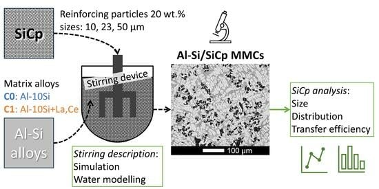
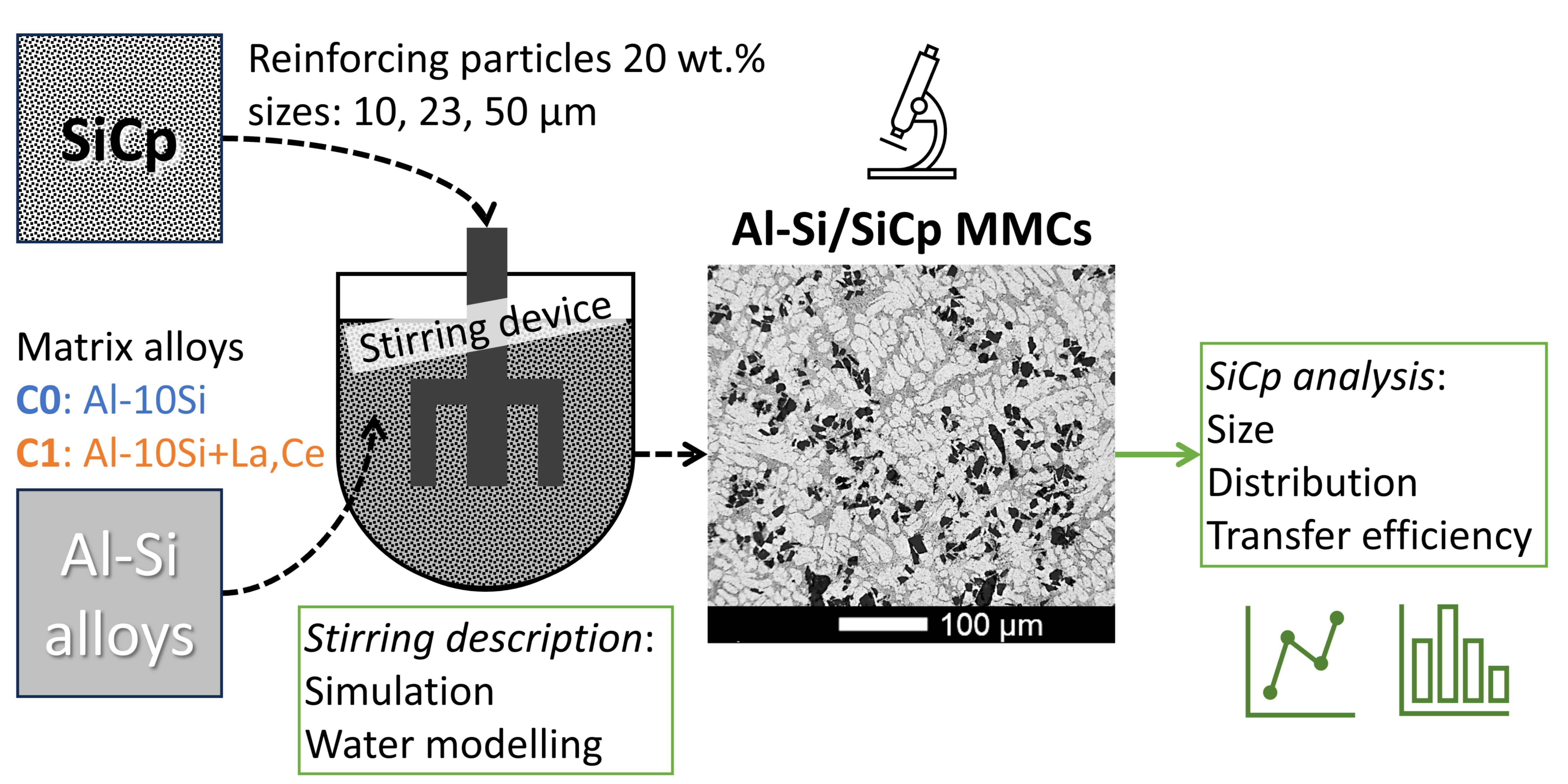
  • Preparation of the composite materials to study the effects of SiCp size and size mix as well as the addition of rare earth elements that have an affinity to oxygen and may change the melt’s wetting behavior.
  • Water modeling with torque and rate of rotation assessment to estimate the shear forces in the pumping head to assess the possibility of breaking SiCp clusters and alumina bifilms that appear when introducing the SiC particles through the melt top surface.
  • Simulation work to understand the flow speeds and general dispersion of the particles in the crucible and to assess the absence of stagnant zones and pseudo cavern formation.
  • Metallographic analysis to assess the transfer efficiency and level of agglomeration and clustering. The resulting data is used together with steps 2 and 3 to explain the origin of losses in particle transfer, particle dispersion, and the agglomeration/deagglomeration effect.

2.1. Material Production and Characterization

2.1.1. Material Production

Five different composite materials were produced by squeeze casting with different SiC particle sizes and matrices. The targeted addition of SiC particles was 20 wt.%, as Jarfors et al. [25] proposed that 20 wt.% of SiC particles could provide enough friction force for the brake disc application. The matrix alloy formulation was based on previous work [22] and the currently available commercial application for automotives [5,26]. The chemical composition of the composite materials, listed in Table 1, were evaluated with optical emission spectroscopy. The Si values include the Si of the matrix alloy and the Si in the SiC particles. The material production process was described in recent work [27].
A newly designed rotor–stator stirring device made of SiC ceramic was used for the stirring process, and the design was modified from the original version of the device developed by Yang et al. [19]. The device’s schematic was also described in previous work [27]; the schematic structure and dimensions of the rotor–stator device are shown in Figure 1. The rotor–stator device was made of silicon carbide, and the crucible was made of clay-bonded graphite. The SiC particles are poured on the molten metal’s surface and then sucked into the melt by the action of the rotor–stator unit. No inert gas protection was used, and the rotor speed was limited to 500 rpm to avoid gas entrainment/cavitation effects and keep the melt surface quiescent while stirring for one hour. The SiC particles were pre-treated at 1000 °C under air atmosphere conditions for 1 h to form a thin SiO2 layer on the SiCp particles [16]. Squeeze casting with 100 MPa of pressure was used to minimize the casting defects, and the mold dimensions’ details were shown in previous work [22]. Each casting experiment produced 4 kg of composite and 30 samples. Randomly, one sample was cut and polished for metallographic observations.

2.1.2. Microstructural Characterization

The samples were prepared for metallographic observation by combining the grinding steps for a hard material and the polishing steps for a soft material. In this case, the SiC particles represent the hard material, and the Al-Si matrix is the soft material. The sequence of grinding and polishing discs (Struers, Ballerup, Denmark) was Piano 220 with water, Largo with 9 µm diamond suspension, Dac with 3 µm diamond suspension, and Dur with 1 µm diamond suspension. Metallographic observations were performed on an optical microscope, the Olympus DSX1000 (Olympus Corporation, Shinjuku, Japan). The SEM observations were performed on the scanning electron microscope JSM-7001f (JEOL, Akishima, Japan).
The SiC particles and particle clusters were analyzed by the MIPAR Image Analysis software (version 4.0.0) on panorama micrographs that covered the entire surface of the samples. The area fraction and diameter of the SiCp clusters were used to evaluate the particles’ dispersion. The particle transfer efficiency is defined in Equation (1) as the ratio between the amount of SiCp evaluated through the image analysis (IA) and the targeted content of SiCps.
S i C p   t r a n s f e r   e f f i c i e n c y = S i C w t . %   a c h i e v e d S i C w t . %   t a r g e t e d
The nearest neighbor distance was calculated based on the centroid coordinates of the SiC particles and the ‘knnsearch’ function in MATLAB R2022b. The average of the nearest neighbor values was used to evaluate the distribution of the carbides.

2.2. Modeling

2.2.1. Water Modeling

A glass tank full of water was used for the water modeling, and the rotor and stator were fabricated by 3D printing (Figure 2). The servo motor (Delta, ASDA-B2) was used for the rotor motion, and the servo controller (Delta, ASDA-B2) was used to control velocity and collect torque and power consumption values.
The tracing particles are lightweight white wax-based particles (Amer Technology Co. Ltd., Guangzhou, China) that are free to move in water to visualize the flow and verify if the rotor–stator device could generate a strong enough flow to disperse the particles in the water homogeneously.
The structure of the rotor–stator device and the experiment parameters in the water modeling experiment were similar to those used in the Al melt stirring experiment. The steady-state velocity gradient, ∂u/∂z, depends on the geometry only, so using the same structure rotor–stator unit in the water modeling experiment resulted in similar experimental parameters to those in the Al melt stirring experiment.
For this reason, using water modeling to evaluate the torque and thus the velocity gradient, ∂u/∂z, in the Al melt stirring experiment was possible. In the measurements from the water modeling experiment, the torque, T w a t e r , is measured to calculate the shear force at the rotor according to Equation (2).
τ w a t e r = T w a t e r A × r
In Equation (2), A is the blade tip area (8.1 10−4 m2), r is the radius of the rotor (0.028 m), and τwater is the shear force generated by the rotor–stator device in the water modeling experiment. This calculation gives an effective measure of the speed gradient in the rotor–stator pumping arrangement, and it is related to the viscosity as in Equation (3). Using τwater [Pa] and the water viscosity, μwater (1 mPa s) [28], in Equation (3), it is possible to obtain ∂u/∂z of in the water modeling experiment.
u z = τ w a t e r μ w a t e r
The assumption is that the system is under a steady state; thus, the speed gradient is only geometry-dependent and, therefore, can be used for both the water and the composite slurry. Equation (4) clarifies the relationship:
τ M M C = μ M M C u z μ M M C τ w a t e r μ w a t e r ,
where τ M M C is the shear stress generated by composite slurry stirring and μ M M C is the viscosity of the composite slurry.

2.2.2. Flow-3D Simulation

The commercial Flow-3D software (version 11.2) simulated the SiC particle stirring and dispersion process, and the structure size of the rotor and stator was the same as for the casting experiment. The AlSi10Mg alloy was chosen for this simulation. The parameters of velocity and temperature were fixed to 500 rpm and 700 °C, respectively. A cartesian grid mesh with a cell size of 1.5 mm and a time step of 0.001 s was used. The applied models are three-dimensional with gravity and a non-inertial reference frame; a general moving object model was used for the particles with a random distribution; and the turbulence model was the renormalized group (RNG) model. The boundary conditions were no wall shear stress or pressure on the top surface. The tracers representing the SiC particles in the simulation were described as spheres with a diameter of 23 μm and a density of 3.2 g/cm3, and the volume fraction was 1% for computational efficiency as their effect on viscosity was regarded as limited [29]. The simulation described the flow pattern of the Al melt during the stirring process.

3. Results and Discussion

The results and discussion will start with the transfer efficiency, followed by the deagglomeration and dispersion of the particles into the melt.

3.1. Particle Transfer Efficiency

Table 2 shows the SiCp transfer efficiency, and data were obtained through the metallographic observation of fifteen images.
The material C0_50 presented a 75.8% transfer efficiency, which was the highest value. The material C0_10 presented a transfer efficiency of 24.1%, which was the lowest value, while the mixed-size particles transferred into the melt with a 42.2% transfer efficiency. The materials with the same size of SiCp but with a different chemical composition of the matrix alloy, materials C0_23 and C1_23, presented transfer efficiencies of 43.6% and 61.9%, respectively. Figure 3 represents the transfer efficiency in relation to the particle size and shows a positive correlation between the two factors.
The material C1_23 was not included in the fitting due to its different matrix composition. The material C1_23 shows a higher transfer efficiency compared with the material C0_23, even though they have the same particle size. This suggests that the La/Ce addition did affect the transfer efficiency.
Figure 4 shows the structure and morphology of the SiC particles after the thermal pre-treatment and before their addition to the melt. After the thermal pre-treatment, the SiC particles tended to agglomerate due to a slight sintering tendency. Figure 4a shows the particles with a particle size of 23 μm, and the agglomeration is visible. Figure 4b shows the particles with a size of 50 μm, the largest particles used in this research, and an agglomeration of particles is not observed. Figure 4c shows the particles with a size of 10 μm, the smallest particles used in the present study, and they show clustering similar to the 23 µm-sized particles. Figure 4d shows the particles with mixed sizes, with a ratio of 1:1:1 = 23 μm:50 μm:10 μm. The small particles with a size of 10 μm adhere to other particles, forming satellite particles on the surfaces of the larger particles with sizes of 23 μm and 50 μm. Figure 4 shows that the mixed-sized particles appear clustered before their addition to the melt, which might affect the transfer efficiency. The material C0_50 shows the highest transfer efficiency, and the particles were not agglomerated before adding the molten metal.
The SiCp particles added in a clustered state mean that each cluster requires the top surface of the molten metal to be broken. The presence of aluminum oxide layers characterizes the surface of the molten aluminum, also referred to as bifilms, according to research by Campbell [30]. These bifilms can interact with the SiCp clusters and wrap the particles, making their dispersion in the melt more difficult. The air sandwiched between the SiC particles of the cluster decreased the density of the clusters, making them highly buoyant. During the addition of SiCps into the melts, the stirring force is a critical factor in transferring the particles into the melts to counteract floatation and settling. The aluminum oxide film encapsulating the SiCp clusters must be fractured to allow melt infiltration. This phenomenon would then decrease the transfer efficiency of the particles. Once the aluminum oxide film is broken, wetting is possible.
Compared to material C0_23, the transfer efficiency of the material C1_23 was 42.5% higher, which indicated that the addition of La and Ce did affect the transfer efficiency. Liu et al. [31] indicated that La and Ce react with Al2O3, forming (La,Ce)2O3, which could reduce the surface energy and promote the wettability of SiCps. According to the Young–Dupre equation [15], reducing the surface energy could decrease the contact angle and promote wettability between the SiC and Al melts. Lloyd [13] reviewed that Mg reacted with Al2O3, forming the spinel crystal MgAl2O4, which increases the wettability of SiC in the molten Al alloy. For this reason, it is interesting to compare the well-known behavior of Mg with La and Ce to better understand their possible contribution in terms of wetting. Table 3 shows the standard Gibbs energy change of oxidation reactions from the Ellingham diagrams [32]; the larger the negative value of the standard Gibbs energy change of the formation ∆G°f [kJ/(mol O2)], the more stable the oxide is. According to the data presented in Table 3 by Hasegawa [32], La has a larger negative value than Mg, which means the affinity of La to O is higher than that of Mg to O, and oxygen (O) is more likely to react with La than with Mg for spinel formation. Based on these values, one can conclude that La and Ce have a behavior similar to Mg in promoting the transfer efficiency of SiC particles.

3.2. Deagglomeration of Clusters

3.2.1. SiC Particle Cluster Strength

Yang et al. [33] used Rump’s model to calculate the tensile strength of a SiC agglomerate using Equation (5). In Equation (5), Tmax is the max tensile strength of the SiC cluster, φ is the volume fraction of SiC particles in the cluster, a is the average radius of the SiC particles, F is the average binding force of a single bond, and nb is the average number of bonds per particle.
T m a x = 9 32 φ π a 2 n b F
The particle–particle cohesive force was in the range of 5 nN to 15 nN for different ceramic particles of similar sizes, as reported by Jones et al. [34]. The work by Jones et al. has already been used as a reference by Yang et al. [19] when investigating the influence of reinforcing particle distributions on the casting characteristics of Al-SiCp composites. ϕ is the maximum packing fraction calculated by Equations (6) and (7), where rp is the aspect ratio of the SiC particles—these equations approximate the Kitano [35] and Pabst [36] models.
Φ S i C = 2 0.321 × r p + 3.02
n S i C n f c c = ϕ S i C ϕ f c c
In Equation (7), nfcc is the maximum number of bonds for an fcc structure, which is 12; nSiC is the maximum number of bonds in a SiC cluster; ϕSiC is the maximum SiC particle package density, and ϕfcc is the packing density of an fcc structure, which is 0.74. After the calculation of Equations (6) and (7), the maximum number of bonds per particle, nSiC, is shown in Table 4, together with the max tensile strength of the SiC particle cluster and the data used in the calculations. The larger particle sizes exhibit a smaller tensile strength, which is reasonably similar to the work by Tzantzis et al. [37].

3.2.2. The Shear Stress Generated by the Stirring Device

The rotor–stator stirring device could generate intensive shearing, and the shear force should break up the particle clusters. While the shear force in the rotor–stator device could not be directly measured, the τ M M C could be calculated from Equations (2)–(4).
Figure 5 shows the relationship between torque and rotation speed in the rotor–stator device. The torque varied as the rotation speed increased.
According to Figure 5, the stirring velocity of 500 rpm corresponded to a torque, T, calculated as 0.051 N×m. Using the viscosity, µ M M C [Pa×s], of the Al-Si/SiCp slurry and the velocity gradient, ∂u/∂z, the shear strength, τ M M C , of the stator during the stirring of the composite slurry was calculated using Equation (4). According to Guth and Simha [29], reported by Yang et al. [33], the viscosity of the Al-Si/SiCp slurry can be calculated from Equation (8) [29], where Φ is the volume fraction of SiC particles shown in Table 2 and µ0 = 1.4 mPa × s is the dynamic viscosity of the Al-10Si-Mg melt [38]:
μ = μ 0 1 + 5 2 Φ + 109 14 Φ 2 .
The shear stress in the holes through the stator wall was calculated from Equation (9) [19]:
τ H = f ρ ϑ 2 2 .
The f is the Fanning friction factor, which is 0.02 for a turbulent flow in a smooth steel pipe [33], ρ is the flow density, and θ is the mean flow velocity. The Flow-3D simulations approximated the flow velocity, θ, to be 8.15 m/s. The composite density was calculated using the rule of mixtures, shown in Equation (10).
ρ c = V p ρ p + V m ρ m
In Equation (10), ρc is the density of the composite material, Vp and Vm are the volume fractions of the SiC particles and matrix alloy, and ρp and ρm are the density values of the SiC particles and the matrix alloy, respectively. The density of the matrix alloy used is 2.7 g/cm3 [39], and the density of the SiC particles is 3.2 g/cm3 [40]. The parameters and calculated data are shown in Table 5. It should be noted that the given speed of 8.15 m/s is an estimate based on the simulations and will be slightly lower in reality. However, the viscosity variations in the added particle ranges in this study will produce a viscosity variation less than the uncertainty of the viscosity variations of the aluminum melt itself, as described by Dinsdale and Quested [41].
In conclusion, the shear stress of the rotor–stator device and the holes through the stator wall was 1.8–5.5 kPa. This shear stress exceeds the shear strength of the SiC clusters, and it may thus be assumed that the shear stress in the rotor–stator region was sufficient to break up the SiCp clusters. This finding is further supported by the fact that Yang et al. [33] calculated the tensile strength of a SiC cluster to be in the range of 6.5–19.5 Pa. It is thus reasonable to conclude that the rotor–stator configuration in the current study would have the ability to fracture a SiC cluster to facilitate the dispersion of individual particles. Kahl et al. [42] evaluated the tensile strength of the 0.2 μm-thick oxide skin to be approximately σmax ≈ 5 MPa. This value is lower than other researchers found, with results ranging from 20 MPa to 250–300 MPa [43]. Due to the high strength of the oxide films, the shear stress generated by the rotor–stator device in the current study would not rupture the oxide skin. If the oxide skin is wrapped around the clusters as they break the top surface during the additions, that would present a problem as the rotor–stator system would be unable to break the cluster oxide skin. This would prevent the air inside the clusters from leaving and aid in the floatation of the SiCp clusters, reducing the transfer efficiency.

3.3. The Flow Pattern in the Furnace

Figure 6 shows the simulation result of the dynamic flow pattern of the slurry in the furnace. The black dots represent the SiC particles based on a Lagrangian formulation for the tracer particles.
The open bottom of the stirring head acts as a pump as it sucks in the slurry and pushes it out through the stator wall holes. Two main circulation regions form patterns similar to pseudo-caverns [44]. The stirring head drives these two flows, with one flow directed upwards, forming pseudo-caverns (A), and another downwards, forming pseudo-caverns (B). The SiC particles follow these two pseudo-caverns moving in the furnace. The different colors label the slurry velocity. The low-velocity zone located at the top of the furnace keeps the fluid level steady and does not allow gas entrance into the melts. In the high-velocity zone inside the stator, the high-velocity gradient will generate an intensive shear strength, so the high shear strength is located at that site. A SiC cluster usually floats up and stays in the low-velocity zone, so putting an SiC cluster into the stirring head will affect the transfer efficiency and particle dispersion.

3.4. Particle Dispersion Analysis

Starting with a qualitative description of the dispersion, the following is observed. Figure 7 shows the morphology of the SiC particles in the composite materials. Figure 7a,e show the 23 μm-particle-reinforced composite, and the SiC particles are homogeneously dispersed in these two composites. Figure 7b shows the 50 μm-particle-reinforced composite, the largest particle size in the matrix. There is no apparent agglomeration observed. Figure 7c shows the 10 μm-particle-reinforced composite, the smallest particle size used in this study, and the SiC particles are easily found in clusters. In Figure 7c, there are traces of oxide films, indicated with an arrow, supporting the hypothesis that clusters may be promoted by oxides, hindering the wetting of the clusters. The idea is that the air inside the cluster is trapped by the oxide film wrapped around the SiC particles and makes the cluster float to the top regions of the melt, where the flow is quiescent. This would then hinder the disintegration of the floated clusters, reducing the transfer efficiency. Figure 7d shows the mixed-particle-reinforced composite, where 10 μm-size particles form satellite particles around the larger sized 23 μm and 50 μm particles and promote the formation of SiC clusters.
The equivalent diameter and average neighbor distance of the clusters were measured, among other geometrical features. Figure 8 represents the image analysis result considering only the clustered SiC particles, neglecting the well-dispersed ones appearing in the matrix alloy.
Table 6 shows the measured values forSiC particle clusters. The average neighbor distance in the materials C0_23 and C1_23 is 1.46 ± 0.81 mm and 1.18 ± 0.86 mm, respectively. All the investigated clusters had an area larger than 0.01 mm2. The material C0_10 shows the smallest average neighbor distance of 0.99 ± 0.71 mm, highlighting the lower quality dispersion of the SiC particles compared to the other composites. The material C0_mix showed a 1.13 ± 0.84 mm average neighbor distance. Due to the addition of 10 μm-sized particles, the dispersion decreased.
The use of large-sized particles reduced the clustering of SiC particles by almost 80%, according to Table 6. The materials C0_23 and C1_23 contain identical particles, and the probability of clusters is expected to be similar for both materials. The fraction of clustered SiC particles reported in Table 6 for the two materials ranges from 10% to 20%. The different matrix alloy resulted in a 53.7% increase in clustered SiC particles, from 13.7% to 21.1%.
The degree of clustering is a critical factor, starting with the clustering tendencies after the thermal pre-treatment and continuing with the agglomerating tendency as they pass through the top surface of the molten metal. The possibility of being coated by an aluminum oxide film when added to the melt can significantly affect the transfer efficiency. These observations are summarized in Figure 9, where the transfer efficiency is plotted against the degree of clustering.
Despite the low value of the regression coefficient (0.87), the linear fitting helps visualize the role of the matrix alloy in the clustering and transferring of SiC particles. A low transfer efficiency is directly related to a high clustering tendency and a reinforcement loss. The red dashed line (refer to colored version) is a rigid translation of the blue fitting line and is added to visualize the possible effect of Ce and La: adding rare earth elements to the matrix alloy increased the transfer efficiency but decreased the particle dispersion. The increased wettability increases the transfer efficiency, but the explanation of the decreased particle dispersion is still somewhat unclear as the reaction has possible effects on both the melt and oxides surrounding the clusters.

4. Conclusions

The current study focuses on an Al-MMC solution for a challenging lightweight application such as brake discs for high-speed trains. The required high-temperature performance for such an application may be addressed by an Al-MMC with rare earth element additions such as Ce and La to improve the strength of the matrix alloy [22]. The addition of SiC as a reinforcing material and rare earth elements affects the material and component fabrication. This paper aimed to investigate what hinders a high transfer efficiency of SiC particles to an Al melt and a good dispersion with a low level of clustering to allow efficient and cost-effective manufacturing. The following observations were made:
  • The required heat treatment to support wetting results in a certain degree of clustering in the SiC particlesafter the thermal pre-treatment. The presence of smaller particles aggravated the degree of clustering.
  • The transfer efficiency increased with increasing particle sizes. The mechanism suggested for this relationship was that the clusters from the pre-treatment were encapsulated by an oxide film during addition, making them buoyant. The pumping action of the rotor–stator device left the top surface quiescent, making it difficult to reintroduce floated clusters and thus reducing the transfer efficiency. The SiCp clusters should break up once entering the stirring head, but the shear stress in the stirring heads was insufficient to break the aluminum oxide skins generated during the melting process.
  • Adding Ce and La increased the transfer efficiency. La, having a high oxygen affinity, could potentially affect the wetting reaction between SiO2, which has a stronger driving force to react with oxygen than Mg. However, this effect on wetting would need further investigation to be fully understood and described.

Author Contributions

Conceptualization, A.E.W.J. and J.Z.; methodology, A.D., L.L. and A.E.W.J.; investigation, A.D. and L.L.; resources, A.E.W.J. and J.Z.; writing—original draft preparation, A.D. and L.L.; writing—review and editing, all authors together; supervision, A.E.W.J., J.Z., G.Y. and K.W.; project administration, A.E.W.J. and J.Z.; funding acquisition, A.E.W.J., J.Z. and L.L. All authors have read and agreed to the published version of the manuscript.

Funding

This research was funded by the Short-term Recruitment Program of Foreign Expert (China), grant 20181215, and the Stiftelsen för Kunskaps-och Kompetensutveckling (Sweden), Prospekt grant ProForAl-20201702.

Data Availability Statement

The data presented in this study are available on request from the corresponding author. The data are not publicly available due to ongoing research and proprietary information.

Acknowledgments

The authors gratefully acknowledge the technical staff at the Department of Materials and Manufacturing of the School of Engineering, Jönköping University. Ansys is gratefully acknowledged for its support with Granta Selector 2023 R1 software through the Research Partnership with Tekniska Högskolan i Jönköping.

Conflicts of Interest

The authors declare no conflict of interest. The funders had no role in the design of the study; in the collection, analyses, or interpretation of data; in the writing of the manuscript; or in the decision to publish the results.

References

  1. Huczko, A.; Dabrowska, A.; Savchyn, V.; Popov, A.I.; Karbovnyk, I. Silicon Carbide Nanowires: Synthesis and Cathodoluminescence. Phys. Status Solidi (b) 2009, 246, 2806–2808. [Google Scholar] [CrossRef]
  2. Xu, H.; Li, X.; Tong, Z.; Zhang, B.; Ji, H.; Cannilla, C.; Vakros, J.; Hapeshi, E.; Xu, H.; Li, X.; et al. Thermal Radiation Shielding and Mechanical Strengthening of Mullite Fiber/SiC Nanowire Aerogels Using In Situ Synthesized SiC Nanowires. Materials 2022, 15, 3522. [Google Scholar] [CrossRef] [PubMed]
  3. Lebedev, A.S.; Suzdal’tsev, A.V.; Anfilogov, V.N.; Farlenkov, A.S.; Porotnikova, N.M.; Vovkotrub, E.G.; Akashev, L.A. Carbothermal Synthesis, Properties, and Structure of Ultrafine SiC Fibers. Inorg. Mater. 2020, 56, 20–27. [Google Scholar] [CrossRef]
  4. Zheng, X.; Lee, H.; Weisgraber, T.H.; Shusteff, M.; DeOtte, J.; Duoss, E.B.; Kuntz, J.D.; Biener, M.M.; Ge, Q.; Jackson, J.A.; et al. Ultralight, Ultrastiff Mechanical Metamaterials. Science 2014, 344, 1373–1377. [Google Scholar] [CrossRef] [PubMed]
  5. Thomas, A.; Zervos, N.; Ekelund, A.; Awe, S.A. Simulation Study on the Thermomechanical Behaviour of Al-MMC Automotive Brake Discs. In Proceedings of the Eurobrake 2019, Dresden, Germany, 21–23 May 2019; pp. 1–12. [Google Scholar]
  6. European Vehicle Emissions Standards—Euro 7 for Cars, Vans, Lorries and Buses. Available online: https://ec.europa.eu/info/law/better-regulation/have-your-say/initiatives/12313-European-vehicle-emissions-standards-Euro-7-for-cars-vans-lorries-and-buses_en (accessed on 23 June 2022).
  7. Serrenho, A.C.; Norman, J.B.; Allwood, J.M. The Impact of Reducing Car Weight on Global Emissions: The Future Fleet in Great Britain. Philos. Trans. R. Soc. A Math. Phys. Eng. Sci. 2017, 375, 20160364. [Google Scholar] [CrossRef] [PubMed]
  8. Kenworthy, J.R. Transport Energy Use and Greenhouse Gases in Urban Passenger Transport Systems: A Study of 84 Global Cities. In Proceedings of the International Sustainability Conference 2003, Fremantle, Western Australia, 17–19 September 2003; pp. 1–28. [Google Scholar]
  9. Hredzak, B.; Gair, S.; Eastham, J.F. Control of an EV Drive with Reduced Unsprung Mass. IEE Proc. Electr. Power Appl. 1998, 145, 600. [Google Scholar] [CrossRef]
  10. Lattanzi, L.; Etienne, A.; Li, Z.; Manjunath, T.; Nixon, N.; Jarfors, A.E.W.; Awe, S.A. The Influence of Ni and Zr Additions on the Hot Compression Properties of Al-SiCp Composites. J. Alloys Compd. 2022, 905, 164160. [Google Scholar] [CrossRef]
  11. Skibo, M.D.; Schuster, D.M. Process for Preparation of Composite Materials Containing Nonmetallic Particles in a Metallic Matrix. U.S. Patent 4,865,806, 12 September 1989. [Google Scholar]
  12. Bao, S.; Tang, K.; Kvithyld, A.; Engh, T.; Tangstad, M. Wetting of Pure Aluminium on Graphite, SiC and Al2O3 in Aluminium Filtration. Trans. Nonferrous Met. Soc. China 2012, 22, 1930–1938. [Google Scholar] [CrossRef]
  13. Lloyd, D.J. Particle Reinforced Aluminium and Magnesium Matrix Composites. Int. Mater. Rev. 1994, 39, 1–23. [Google Scholar] [CrossRef]
  14. Hashim, J.; Looney, L.; Hashmi, M.S.J. Metal Matrix Composites: Production by the Stir Casting Method. J. Mater. Process. Technol. 1999, 92–93, 1–7. [Google Scholar] [CrossRef]
  15. Malaki, M.; Tehrani, A.F.; Niroumand, B.; Gupta, M. Wettability in Metal Matrix Composites. Metals 2021, 11, 1034. [Google Scholar] [CrossRef]
  16. Ureña, A.; Martínez, E.E.; Rodrigo, P.; Gil, L. Oxidation Treatments for SiC Particles Used as Reinforcement in Aluminium Matrix Composites. Compos. Sci. Technol. 2004, 64, 1843–1854. [Google Scholar] [CrossRef]
  17. Shanmuga Priyan, V.G.; Kanmani, S. Effect of Ultrasonic Treatment during Stir Casting on Mechanical Properties of AA6063-SiC Composites. Mater. Chem. Phys. 2023, 294, 126977. [Google Scholar] [CrossRef]
  18. Fan, Z.Y.; Zuo, Y.B.; Jiang, B. A New Technology for Treating Liquid Metals with Intensive Melt Shearing. Mater. Sci. Forum 2011, 690, 141–144. [Google Scholar] [CrossRef]
  19. Yang, X.; Barekar, N.S.; Ji, S.; Dhindaw, B.K.; Fan, Z. Influence of Reinforcing Particle Distribution on the Casting Characteristics of Al-SiCp Composites. J. Mater. Process. Technol. 2020, 279, 116580. [Google Scholar] [CrossRef]
  20. Capes, C.E. The Correlation of Agglomerate Strength with Size. Powder Technol. 1972, 5, 119–125. [Google Scholar] [CrossRef]
  21. Wilks, G.B. The Influence of Reinforcement Homogeneity on the Deformation and Fracture of Discontinuously Reinforced Aluminum Matrix Composite. Ph.D. Thesis, Pennsylvania State University, Graduate School College of Earth and Mineral Sciences, University Park, PA, USA, 2007. [Google Scholar]
  22. Du, A.; Jarfors, A.E.W.; Zheng, J.; Wang, K.; Yu, G. The Influence of La and Ce on Microstructure and Mechanical Properties of an Al-Si-Cu-Mg-Fe Alloy at High Temperature. Metals 2021, 11, 384. [Google Scholar] [CrossRef]
  23. Du, A.; Lattanzi, L.; Jarfors, A.W.E.; Zheng, J.; Wang, K.; Yu, G. On the Hardness and Elastic Modulus of Phases in Sic-Reinforced al Composite: Role of La and Ce Addition. Materials 2021, 14, 6287. [Google Scholar] [CrossRef]
  24. Du, A.; Lattanzi, L.; Jarfors, A.E.W.; Zhou, J.; Zheng, J.; Wang, K.; Yu, G. The Influence of Ce, La, and SiC Particles Addition on the Formability of an Al-Si-Cu-Mg-Fe SiCp-MMC. Materials 2022, 15, 3789. [Google Scholar] [CrossRef]
  25. Jarfors, A.E.W.; Ghasemi, R.; Awe, S.; Jammula, C.K. Comparison between High-Pressure Die-Cast and Rheo-Cast Aluminium SiCp MMC; Wear and Friction Behaviour. La Metall. Ital. 2021, 12, 13–18. [Google Scholar]
  26. Awe, S.A.; Thomas, A. The Prospects of Lightweight SICAlight Discs in the Emerging Disc Brake Requirements. In Proceedings of the Eurobrake 2021, Online, 18–20 May 2021; pp. 1–6. [Google Scholar]
  27. Du, A.; Lattanzi, L.; Jarfors, A.E.W.; Zheng, J.; Wang, K.; Yu, G. Role of Matrix Alloy, Reinforcement Size and Fraction in the Sliding Wear Behaviour of Al-SiCp MMCs against Brake Pad Material. Wear 2023, 530, 204969. [Google Scholar] [CrossRef]
  28. Bird, B.R.; Stewart, W.E.; Lightfoot, E.N. Transport Phenomena, 2nd ed.; John Wiley & Sons: Hoboken, NJ, USA, 2006; ISBN 978-0-470-11539-8. [Google Scholar]
  29. Guth, E.; Simha, R. Untersuchungen Über Die Viskosität von Suspensionen Und Lösungen. 3. Über Die Viskosität von Kugelsuspensionen. Kolloid-Zeitschrift 1936, 74, 266–275. [Google Scholar] [CrossRef]
  30. Campbell, J. The Melt. In Castings; Elsevier: Amsterdam, The Netherlands, 2003; pp. 1–16. [Google Scholar]
  31. Liu, Q.; Wang, F.; Qiu, X.; An, D.; He, Z.; Zhang, Q.; Xie, Z. Effects of La and Ce on Microstructure and Properties of SiC/Al Composites. Ceram. Int. 2020, 46, 1232–1235. [Google Scholar] [CrossRef]
  32. Hasegawa, M. Ellingham Diagram. Treatise Process Metall. 2014, 1, 507–516. [Google Scholar] [CrossRef]
  33. Yang, X.; Huang, Y.; Barekar, N.S.; Das, S.; Stone, I.C.; Fan, Z. High Shear Dispersion Technology Prior to Twin Roll Casting for High Performance Magnesium/SiCp Metal Matrix Composite Strip Fabrication. Compos. Part A Appl. Sci. Manuf. 2016, 90, 349–358. [Google Scholar] [CrossRef]
  34. Jones, R.; Pollock, H.M.; Geldart, D.; Verlinden, A. Inter-Particle Forces in Cohesive Powders Studied by AFM: Effects of Relative Humidity, Particle Size and Wall Adhesion. Powder Technol. 2003, 132, 196–210. [Google Scholar] [CrossRef]
  35. Kitano, T.; Kataoka, T.; Shirota, T. An Empirical Equation of the Relative Viscosity of Polymer Melts Filled with Various Inorganic Fillers. Rheol. Acta 1981, 20, 207–209. [Google Scholar] [CrossRef]
  36. Pabst, W.; Gregorová, E.; Berthold, C. Particle Shape and Suspension Rheology of Short-Fiber Systems. J. Eur. Ceram. Soc. 2006, 26, 149–160. [Google Scholar] [CrossRef]
  37. Tzamtzis, S.; Barekar, N.S.; Hari Babu, N.; Patel, J.; Dhindaw, B.K.; Fan, Z. Processing of Advanced Al/SiC Particulate Metal Matrix Composites under Intensive Shearing—A Novel Rheo-Process. Compos. Part A Appl. Sci. Manuf. 2009, 40, 144–151. [Google Scholar] [CrossRef]
  38. Wei, P.; Wei, Z.; Chen, Z.; He, Y.; Du, J. Thermal Behavior in Single Track during Selective Laser Melting of AlSi10Mg Powder. Appl. Phys. A 2017, 123, 604. [Google Scholar] [CrossRef]
  39. Al-10Si alloy, Granta Selector 2023 R1, Version 23.1.1, consulted in August 2023.
  40. Silicon carbide particles (SiCp), Granta Selector 2023 R1, Version 23.1.1, consulted in August 2023.
  41. Dinsdale, A.T.; Quested, P.N. The Viscosity of Aluminium and Its Alloys—A Review of Data and Models. J. Mater. Sci. 2004, 39, 7221–7228. [Google Scholar] [CrossRef]
  42. Kahl, W.; Fromm, E. Examination of the Strength of Oxide Skins on Aluminum Alloy Melts. Metall. Trans. B 1985, 16, 47–51. [Google Scholar] [CrossRef]
  43. Engler, S.; Ellerbrok, R. Über Das Formfüllungsvermögen Der Gusswerkstoffe. Giessereiforschung 1974, 26, 49–62. [Google Scholar]
  44. Doucet, L.; Ascanio, G.; Tanguy, P.A. Hydrodynamics Characterization of Rotor-Stator Mixer with Viscous Fluids. Chem. Eng. Res. Des. 2005, 83, 1186–1195. [Google Scholar] [CrossRef]
Figure 1. The schematic structure and dimensions of the rotor–stator device.
Crystals 13 01621 g001
Figure 2. Experimental setup of the water modeling, showing the drive rod, rotor–stator device, and tracing particles for flow visualization. The vertical ruler serves as a scale bar.
Crystals 13 01621 g002
Figure 3. A diagram of particle transfer efficiency vs. average particle size.
Crystals 13 01621 g003
Figure 4. Appearance of SiC particles after the thermal pre-treatment: (a) 23 µm; (b) 50 µm; (c) 10 µm; (d) mix of the three dimensions.
Crystals 13 01621 g004
Figure 5. The relationship between the torque and the rotation speed in the rotor–stator device used for water modeling.
Crystals 13 01621 g005
Figure 6. The rotor–stator device stirring Flow-3D simulation (500 rpm).
Crystals 13 01621 g006
Figure 7. The morphology of SiC particles in the composite: (a) material C0_23; (b) material C0_50; (c) material C0_10, where the arrow indicates the residues of an oxide film; (d) material C0_mix; (e) material C1_23.
Crystals 13 01621 g007
Figure 8. The method used to analyze the SiC clusters (material C1_23): (a) before and (b) after cluster detection in the MIPAR software.
Crystals 13 01621 g008
Figure 9. The transfer efficiency versus the degree of clustering confirms that the clustering level and the chemical composition of the matrix alloy influence the transfer efficiency. The linear fitting (blue solid line) on the C0 materials and its rigid translation (red dashed line) to the C1 material are meant to highlight the role of the different matrix alloys.
Crystals 13 01621 g009
Table 1. Chemical composition of composite materials [wt.%], including the SiC particles 1.
MaterialSiCp Size [µm]SiFeCuMnMgNiTiCeLa
C0_232315.80.70.00.00.70.00.1--
C0_505021.20.50.00.00.70.00.1--
C0_101010.90.40.10.00.60.10.1--
C0_mix10 + 23 + 50 217.40.20.00.00.80.00.1--
C1_232319.80.51.90.90.81.90.40.60.7
1 The carbon was not included in the analysis due to equipment limitations. 2 The different sizes were added at equal mass ratios in the material C0_mix.
Table 2. Particle image analysis and evaluation of the transfer efficiency. The quantitative image analysis was performed on panorama images that covered the entire surface of the samples.
MMCC0_23C0_50C0_10C0_MixC1_23
Average particle size [μm]14 ± 0.932 ± 1.412 ± 1.819 ± 1.515 ± 1.1
SiCp wt.% targeted fraction20%20%20%20%20%
SiCp wt.% fraction8.7%15.2%4.8%8.5%12.4%
SiCp transfer efficiency43.6%75.8%24.1%42.2%61.9%
Table 3. The standard Gibbs energy change of oxidation reactions by Hasegawa [32].
ElementLaCeMgAlTiSiMnFeCu
∆G°f [kJ/(mol O2)]−1055−880−992−900−845−728−624−400−200
Table 4. The calculated maximum strength of particle clusters.
MMCC0_23C0_50C0_10C0_mixC1_23
rp1.86 ± 0.0231.81 ± 0.0441.75 ± 0.0361.72 ± 0.0111.73 ± 0.014
ϕSiC0.55290.55530.55830.55980.5593
nSiC8.979.019.059.089.07
a [μm]7 ± 0.4516 ± 0.706 ± 0.909.5 ± 0.757 ± 0.55
Tmax [Pa]44.45–136.378.7–26.2262.47–187.4324.98–74.9645.98–137.98
Table 5. The parameters that were used to calculate the shear strength and the calculated result.
MMCC0_23C0_50C0_10C0_MixC1_23
µ [Pa·s]2.10 × 10−32.46 × 10−31.56 × 10−32.00 × 10−32.10 × 10⁻³
τ M M C [kPa]4.024.913.583.994.50
ρ [kg/m3]27432776272427432762
τH [kPa]1.801.821.781.801.81
Table 6. The results of the image analysis on SiCp clusters.
MMCC0_23C0_50C0_10C0_mixC1_23
Average neighbor distance [mm]1.46 ± 0.813.95 ± 2.560.99 ± 0.711.13 ± 0.841.18 ± 0.86
Area fraction of SiC particles7.5%13.1%4.1%7.2%10.7%
Area fraction of SiCp clusters1.9%0.7%2.8%2.5%4.0%
Fraction of clustered SiC particles13.7%2.9%37.7%19.0%21.1%
Variation in clustered SiC particles compared to C0_23 −78.8%+174.4%+38.6%+53.7%
Disclaimer/Publisher’s Note: The statements, opinions and data contained in all publications are solely those of the individual author(s) and contributor(s) and not of MDPI and/or the editor(s). MDPI and/or the editor(s) disclaim responsibility for any injury to people or property resulting from any ideas, methods, instructions or products referred to in the content.

