Article

Stretching and Compression of Double Dusty Plasma Vortex

1
Institute for Laser, Plasma and Radiation Physics, Atomiştilor 409, 077125 Măgurele, Romania
2
Horia Hulubei National Institute for R&D in Physics and Nuclear Engineering, 077125 Măgurele, Romania
*
Author to whom correspondence should be addressed.
Crystals 2023, 13(1), 76; https://doi.org/10.3390/cryst13010076
Submission received: 2 December 2022 / Revised: 22 December 2022 / Accepted: 28 December 2022 / Published: 1 January 2023

Abstract

:
The interest in complex plasmas is increasing due to the multiple applications they target (astrophysics, plasma fusion, industry, etc.). A crystal with two vortexes made of spherical microparticles that levitates in an rf plasma interacts with a gas jet. The crystal is displaced in the jet propagation direction due to the neutral pushing force, maintaining its vortex structure. The crystal shift also involves a change of its shape, especially at the level of the two vortexes. One vortex is stretched, and the other one is compressed. During the three phases of modification of the shape of the crystal, its length is approximately constant, about 12.5 mm, this being a consequence of the fact that electric forces and ion drag forces are preserved. The orderly structure of the crystal lasts until the particles begin to fall on the bottom electrode. The changing of the vorticity in the crystal regions can be attributed to the neutral push force.

1. Introduction

Dusty plasma, often called complex plasma, is made of charged ions or molecules, electrons, fields, and particles of matter. The study of dusty plasma is of interest to many areas of physics, such as astrophysics (Saturn and Jupiter rings, comet tails, meteoric dust, zodiac light, etc.), semiconductor technology, and microchips. The field of dusty plasma in the literature has an interdisciplinary character covering a wide range of physical phenomena, as well as applications at the technological and industrial level [1]. In the latter case it is sufficient to think, for example, of fragments of dust in fusion plasmas where strong interactions of high-energy plasma with tokamak walls will produce material impurities. These solid microparticles cover a wide range of sizes from a few nm to mm. Fusion reactors produce ionizing radiation (especially neutrons). This dust produced by the erosion of walls, an electric arc, surface peeling, and impurities can be radioactive (by activating tritium dust particles) and can lead to instabilities [2]. At the same time, this powder can play a positive role and can be used as a diagnostic tool in plasma [3]. Dusty plasmas also show similar behavior with microscopic phenomena such as solid–liquid phase transition [4], the formation of crystals [5,6], viscous heating [7,8,9], and dust flow dynamics [9]. A special case of a dusty plasma is the plasma crystal. Spherical microparticles once immersed in low-temperature plasma start charging with electrons and ions. The microparticles levitate and occupy specific positions in the plasma, with their spatial distribution being periodic. Depending on the plasma parameters (pressure and electric power), the system can oscillate between the liquid and crystal states. Conditions can also be found to study the phase transition. The presence of vortexes in a dusty plasma is a great opportunity to investigate turbulent flow and instabilities [10]. In the community of dusty plasma physics, there are several ideas to explain the nature of vortexes. M. R. Akdim and W. J. Goedheer [11] argued that non-conservative forces exerted by the discharge on the dust particles are responsible for the production of vortices. Other authors such as Shimizu et al. [12] have come to the conclusion that the vortices are caused by a temperature gradient between the two electrodes. Others researchers (Fortov et al. [13]) argued that the dust vortex is the result of the case when the gradient of dust-charge is not parallel to non-electrostatic forces (gravitational force and ion drag force). An interesting analogy to the poloidal magnetic field is made by Kil-Byoung Chai and Paul M. Bellan [14].
The vortices created experimentally in dusty plasma are generally made in Ar and have a stationary character. An extensive theoretical approach was realized to describe the vortexes’ dynamics [15,16,17,18]. To the authors’ knowledge, the manipulation by kinetic displacement of a dusty plasma with vortexes has not been reported before. In our experiment, the dusty plasma featuring two vortices produced in CO2 gas and rf discharge was transported and preserved for a period of several seconds using neutral drag force.

2. Experimental Setup

In our experiments we use a ‘’six-cross”-type vacuum chamber, two vacuum pumps (a preliminary one to obtain a pressure of 10−2 Torr and a turbomolecular one to gain high vacuum which reach a value of 10−5 Torr), a radio frequency generator, and a laser that operates at 20 mW. We introduce CO2 gas inside the vacuum chamber at a pressure of 250 mTorr to create an rf plasma between two parallel electrodes placed as in Figure 1. The lower electrode is capacitively coupled to a voltage source of 13.56 MHz, and the upper electrode is grounded. The electric power that ignites the plasma is 2W. With the help of a dispenser tool, we immerse the polystyrene particles into the plasma spherical micrometric particles with a diameter of 14.45 µm and a density ρ = 1.05 g cm−3. Once immersed in the rf plasma, the monodisperse polystyrene particles behave like probes that collect electrons and ions. Using a high-speed camera (Photron) that is positioned sideways, we can capture detailed images of the plasma crystal, which also serve as a tool to measure interparticle distances and grains velocities. The particles are illuminated by a He-Ne laser beam passed through a cylindrical lens. A great help in the acquisition of plasma parameters is brought by a Langmuir probe, especially for inferring the electron temperature and density. The schematic diagram of the experimental arrangement can be seen in Figure 1.
Under these conditions, we obtain a crystal of centimeter dimensions (Figure 2) with an average interparticle distance d = 40   μ m . The peculiarity of this crystal is marked by the presence of two symmetrical vortexes in the crystal extremities. In Figure 2, we can see the two phases of the crystal; in the middle zone the particles are static, and in the extremities the particles move continuously in trajectories with an ellipsoidal shape.
A Voronoi diagram [19] with a top view of the crystal in the region where the particles are stable can be seen in the Figure 3. Most cells have a hexagonal shape (hcp). While the bcc and fcc formations [6,20,21,22,23] can appear in dusty plasma, the hpc structure is more often found in those experiments where ion flow plays a significant role. We notice in the Voronoi diagram how the polygons on the left correspond to the solid area of the particle cloud, while on the right they are wider, a sign that indicates the area where the vortices appear.
For the region of the two vortices, a brief analysis of the divergence of the velocity field shows values close to zero. We know from the equation of continuity [24], v = 0 , that incompressibility is achieved when the divergence is zero. We can see from Figure 4 how the divergence values are slightly different from zero. Taking into account the values for divergence near to zero on the region of the two vortexes and the stable central area analyzed by the Voronoi diagram, it can be considered that in this dusty plasma the crystalline and the liquid phases coexist together. A similar situation was reported [5,25] in an argon plasma with spherical microparticles, with the difference that the liquid state was obtained by melting the crystalline structure by varying the discharge current. Other experiments [26] with thermal plasmas (1700–2200 K) confirm the mixture of states and the phase transition through melting.

3. Results and Analyses

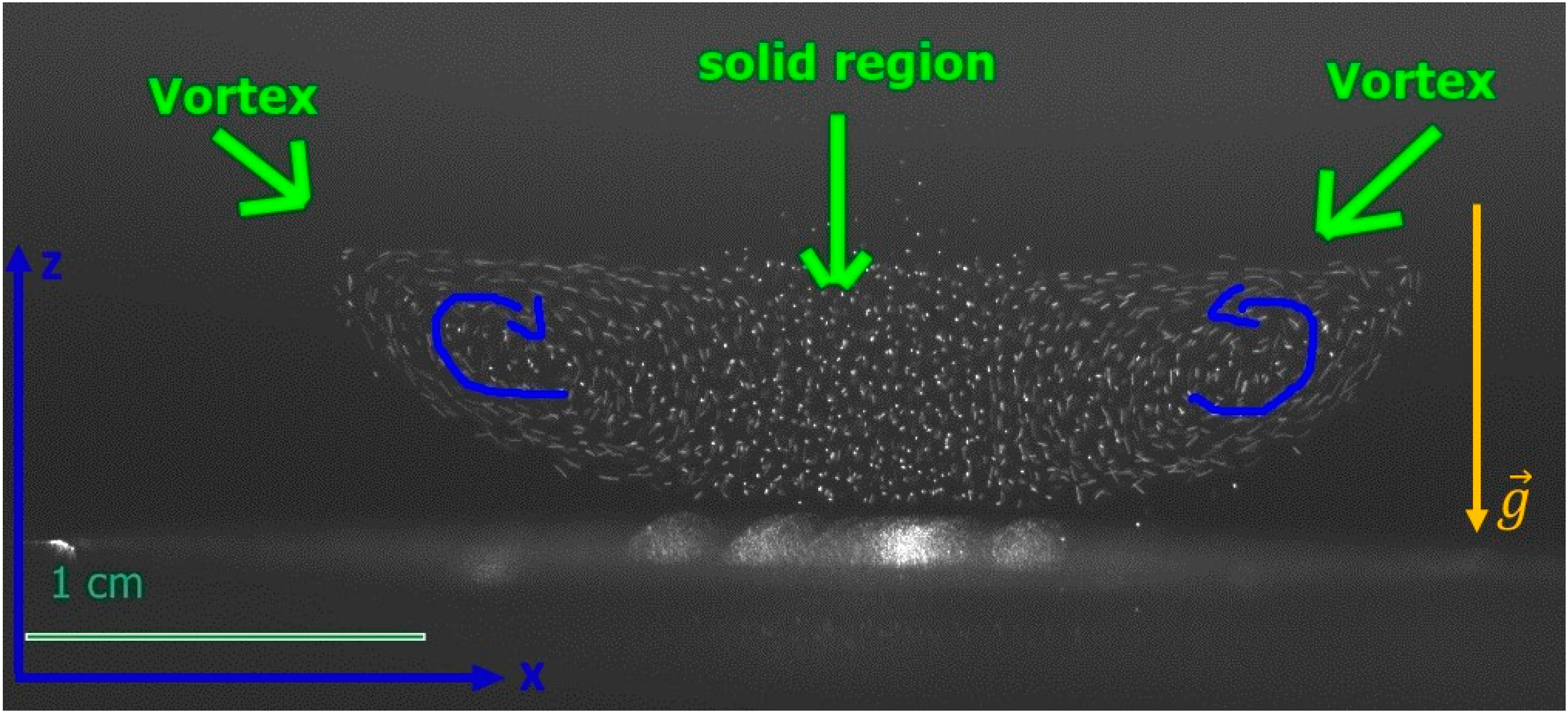
3.1. Experimental Observations

Initially, the crystal stays in place and the vortices rotate with constant speed and vorticity at a pressure of 250 mTorr and an electric power of 2 W. After introducing the gas into the vacuum chamber at constant speed through the gas valve, we observe the collective displacement of the particles in the crystal in the direction of gas propagation. The shift of the particles is in the direction of gas flow that we see in Figure 5b,c. In Figure 2 and Figure 5, the movement of the crystal is along the x axis, more precisely from +x to −x. Gravity acts in the direction of the −z axis. For this reason, it is reasonable to assert that the crystal displacement is done by pushing the neutral gas particles. The crystal shift also involves a change of its shape, especially at the level of the two vortexes. One vortex was stretched, and the other was compressed. In Figure 5, we can observe three phases associated with evolution of the crystal. The displacement of the crystals takes 2.5 s, and then the particles fall to the down electrode. Three regions of the speed of the crystal vortexes can be identified. In Figure 5d, a significant increase in average rotational speed can be observed from the moment the crystal is displaced up to twice the initial speed.
In the interval of 1–2 s, the average speed starts to decrease, being a possible consequence of the fact that the pressure in the enclosure increases and the friction with the neutral gas is greater; then, it decreases even more steeply after 4 s, a phenomenon associated with the particles falling on the electrode. When this happens, the gas pressure in the chamber increases to 700 mTorr, almost three times more than the initial condition.
During the three phases of crystal shape modification and its displacement of 7 mm on the x axis (from +x to −x), its length is approximately constant, about 12.5 mm. This could be a consequence of the fact that the electric and ion drag forces are preserved until the crystal reaches the edge of the confining region, where the electric field between the electrodes is uniform.

3.2. Estimation of Forces

The rotation of dust particles results from the cooperation of several forces. The forces that ensure the cohesion of the crystal are the gravity force, the electric force inside the plasma sheath, the neutral drag force, a weak horizontal confining force, and the ion drag force. Gravity ( F g = m d g = 4 3 π r d 3 ρ d g ) acts downward with a value of 1.62 × 10⁻¹¹ N, where r d is the radius of the dust microparticle, ρ d is its density, and g is the gravitational acceleration. The particles are trapped in the plasma sheath by the electric force. A general relationship is F E = Q d E , where E is the electric field. In order for the dust particles to be levitated Q d E m d g , with the electric field E pointing downward.
Taking into account that the crystal floats above the bottom electrode coupled to the rf high-voltage source and inside the plasma sheath, the electric field will vary depending on the height above the electrode. The particles in the cloud that are at the top of the dust cloud in the vicinity of the plasma (at a distance of 1 mm) see an electric field of approximately | E | = 70 Vcm−1, while the particles deep into the sheath (at a height 6 mm) see an electrical field approximately five times larger, | E | = 350 Vcm−1. From the above relations, Q d 1.4 × 10 4 and 2.9 × 10 3 e , respectively, where e is the elementary charge, at the two heights. Here, we consider a parabolic potential profile inside the sheath [27], and we neglect the wake potential exerted by the top dust particles at the position of the bottom dust particles, which in principle can influence the local electric field [28].
An estimation of the repulsion interaction force between two charged grains found at the top of the crystal is F d d = 1.25 × 10 11 N, using F d d = Q d 2 4 π ε 0 d 2 e d λ D , where λ D = ( λ D e 2 + λ D i 2 ) 1 / 2 is the Debye length [28], and λ D e , i = ε 0 k B T e , i e 2 n e , i are the electron and ion Debye’s lengths. In our case, λ D λ D i = 45   μ m . For the ion temperature Ti, we consider ions almost as hot as the neutral gas, at 290 K. Thus, the horizontal confining force that holds the dust crystal is of the order of F d d such that the dust particles do not drift away due to their own repulsion.
The electron temperature T e was measured with a Langmuir probe and had a value T e 4.5 ± 0.2 eV, while the density of electrons in the plasma was n e 6.7 ± 0.3 × 10 14 m−3 for a neutral gas pressure of 250 mtorr. Additionally, for the evaluation of the sheath electric field profile values of the plasma potential V P = 24 V and dc bias on the rf electrode V D C = 150 V were utilized. Here, we neglect the production of negative ions within the CO2 plasma given that the rf power fed into the discharge is low (2 W).
The combination of electric force and its associated dust-charge gradient together with the ion drag force can be the main cause of the formation of vortices in the plasma, as argued by Fortov about the experiments carried out onboard the Alpha International Space Station [13]. Using the approach of Fortov and Morfill [29] and Lipaev et al. [30], we can estimate the drag force as F i 8 2 π 3 r d 2 n i m i v t i u i o n G , where n i = n e is the ion density; m i = 44   u is the mass of CO2 ions ( u = 1.67 × 10 27 kg); v t i is the thermal velocity of ions ( 375 ms−1); u i o n is the streaming velocity of ions accelerated into the sheath field (higher than the Bohm velocity k B T e m i ); and G is a function of the Coulomb logarithm (considering the collisions of ions with a dust particle), the normalized dust charged, and the ratio of electron to ion temperature.
A value of 0.6 × 10 12 N for the ion drag force can be attained when u i o n 2 × 10 4 ms−1 and G 10 , close to the value of the electric force, and could be the main cause for vortexes. The direction of the ion drag force producing the two vortexes with opposite rotations is consistent with the flow direction of the streaming ions, from the bulk plasma to the rf electrode. A similar pushing effect caused by the ion drag force that formed a void of dust particles inside a plasma crystal has been observed in microgravity conditions [30]. At the end of the stretching and compression process, we can see how the particles are free falling, unable to be sustained by the electric forces.
Neutral drag force is important in our experiment as the force of friction of the dust particles with the neutral gas, but also as the force of pushing the whole crystal. Using the approach described by Melzer [28], the neutral drag force is given by F n = m d β v d , where v d is a measured dust speed of 6 cm/s of the motion on the vortex and β is the friction (Epstein) coefficient which depends of gas pressure, β = δ 8 π p r ρ d v t h , n . The coefficient δ was calculated by Epstein in 1924 to analyze friction in Millikan’s oil drop experiment and represents the parameter for diffuse reflection, with a value of 1.44. For the thermal neutral velocity v t h , n , for CO2 at a temperature, T = 300 K, we use v t h , n = 8 k B T π m , with k B the Boltzmann constant and m the mass of a CO2 molecule. The value is F n = 4.48 × 10 12 N in the initial phase at the pressure of 250 mTorr, but after we introduce the gas and the particles start to fall at the final pressure of 700 mTorr, the force value is F n = 1.25 × 10 12 N. The drag force that pushes the whole crystal in the direction of gas propagation is much stronger due the high flow speed injected towards the crystal, which is of the order of the sonic speed in CO2 ( ~ 10 2 ms−1). The drag force that pushes is given by F d r a g = 1 2 ρ g a s v d i s p l 2 C d r a g A , where gas density, ρ g a s , for CO2 is 5.06 g/L; v d i s p l is the gas particle speed, C d r a g ; and A is the drag coefficient and the area of a half sphere.
Thus, the drag force is four orders of magnitude higher than F n : F d r a g 10 8 N. This strong force is important in our experiment because it is responsible for the deformation of the crystal. The high flow velocity of the neutral gas that exerts a thrust differs considerably from the rate at which the microparticles spin into vortexes. This difference in velocities may be related to the Kelvin–Helmholtz effect [24,31,32]. The regions in our system where there is interaction between the pushing stream of gas and the rotational circulation of microparticles can be viewed like two fluids with different behaviors.

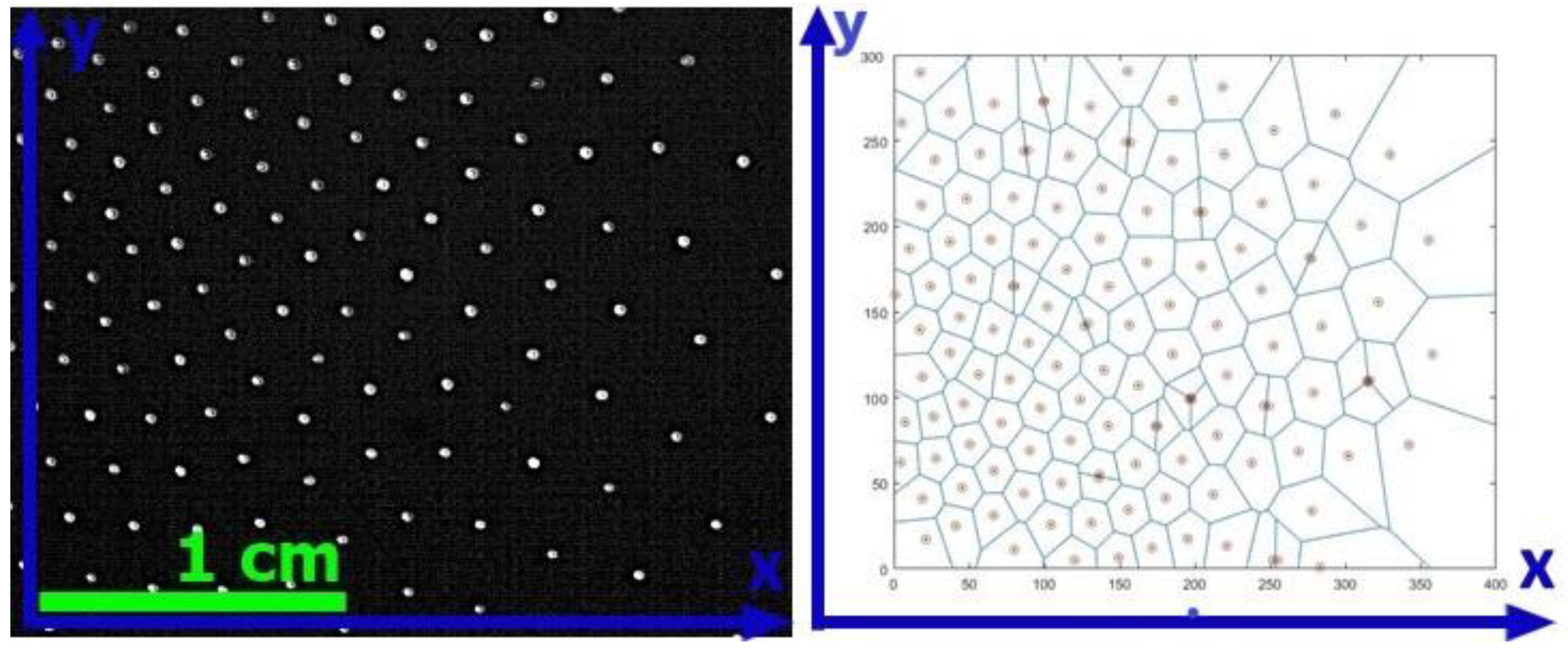
3.3. Particle Image Velocimetry (PIV) Analysis

A short PIV analysis [33] shows that in the first phase the vorticity of the flow field, ω = × v d , is not constant like in the case of a rigid rotating disc, but it shows a gradient of vorticity with values of 2 to 14 s−1 (as in Figure 6a). The highest values of vorticity can be seen in center of the vortexes. In the edge regions of the crystal, a strong velocity shear in the form of narrow islands situated above and below the vortexes can be seen. Initially, after the neutral gas pushing force displaces the crystal, we can observe an increasing value for the central vortex and edge vortexes from 12–14 s−1 to 17–20 s−1 (Figure 6b). This increase in vorticity can be attributed partially to the dissipation of the energy of the pushing force of the neutral gas. Additionally, the stretching and compression phenomena of vortexes associated with the increasing vorticity can be related to the Kelvin–Helmholtz instability. After 3.25 s, the maximum vorticity of both vortexes drops to 2–6 s−1 for the central region and to 16 s−1 for the narrow island of the stretched vortex (Figure 7). The decrease in vorticity after a few seconds can be attributed to a higher density of the neutral gas introduced into the chamber, which makes the friction with the neutral gas greater. A similar effect was reported in [34]; however, the cloud of particles from the DC plasma increased its width with increasing pressure. In our experiment, the dimension of the dusty plasma system remains almost constant by increasing the gas pressure up to 700 mTorr.
Another group [35,36] reported particle vortices in DC plasma behaving like a rigid solid, with a velocity profile varying from low velocities in the center to high velocities outwards (exactly opposite to our experiment), a pattern similar to the behavior of rotating solid bodies. The explanation is that the particles move downward against the sheath electric field in the zones of higher ion drag force and upwards in the zones with lower ion drag force. In our experiment, the flow at the level of vortices can be seen as a laminar flow. Taking into account the Reynolds number, R e = v w ϑ , considering the kinematic viscosity [37] ϑ = 0.01 cm−2 s−1; the velocity of dust, v = 2.84 cm/s and D= 0.8 cm; and the diameter of the circular edge of the particles farthest from the center of the vortex, we estimate a value R e = 227 . According to the criteria of classical fluids, this corresponds to a laminar flow regime, at the upper limit of the regime of viscoelastic fluids [38,39]. Higher values, over 2500, would refer to turbulence behavior in classical fluids.

4. Conclusions

Using rf CO2 rf plasma, we obtain a special dusty plasma system with two vortices that can be seen as a structure with both crystalline and liquid phases. The collective displacement of 7 mm on a horizontal axis is achieved by triggering a neutral gas pushing force. Crystal shift also involves a change of its shape, especially at the level of the two vortexes. One vortex is stretched, and the other is compressed. The cohesion of the crystal subjected to the pushing neutral gas force is ensured by the electric and the confining forces. The value of the drag force 10 8 N is orders of magnitude higher than the ion drag force, 0.6 × 10 12 N, thought to be responsible for the observed rotation of the vortexes and the electrostatic force between charged grains 1.25 × 10 11 N. As the gas flow impinges on the dust particles, the crystal is slightly modified, mainly on the level of vortices. The crystal has a translational movement in which its structure is preserved. In contrast, a much greater drag force such as the one produced by a coaxial plasma gun blows away the entire crystal and breaks its cohesion forces [40].
The presence of vortexes in a dusty plasma is a great opportunity to investigate turbulent flow and instabilities. Increased vorticity can be caused by energy dissipation from the neutral gas pushing force and could also be connected to the Kelvin–Helmholtz instability.
We did not consider the effect of negative ions, given the fact that we are dealing with an electronegative plasma. Future investigations aim to detail and quantitatively estimate the effect of negative ions. They can have an influence on the transport and spatial distribution of charged particles as well as on the structure of the sheath [41].

Author Contributions

Conceptualization, A.S.; methodology, A.S. and D.T.; software, M.L.M.; validation, A.S., D.T. and C.M.T.; formal analysis, N.U.; investigation, M.L.M.; resources, A.S.; data curation, N.U.; writing—original draft preparation, A.S.; writing—review and editing, A.S. and M.L.M.; visualization, D.T.; supervision and writing, C.M.T.; project administration, A.S. and D.T; and funding acquisition, A.S. All authors have read and agreed to the published version of the manuscript.

Funding

This research was funded by Ministry of Research, Innovation, and Digitization under contract NUCLEU LAPLAS VI, P.N. 19. 15/16N2019, and by the Romanian Space Agency (ROSA) under contract DUSTEXSPACE nr. 123 Competition C3-2016 and PN 18 13 01 01.

Acknowledgments

Special thanks to our technician Emil Constantin.

Conflicts of Interest

The authors declare no conflict of interest.

References

  1. Merlino, R.L. Dusty plasmas and applications in space and industry. Plasma Phys. Appl. 2006, 81, 73–110. [Google Scholar]
  2. Ratynskaia, S.; Bortolon, A.; Krasheninnikov, S.I. Dust and powder in fusion plasmas: Recent developments in theory, modeling, and experiments. Rev. Mod. Plasma Phys. 2022, 6, 20. [Google Scholar] [CrossRef]
  3. Samarian, A.A.; Kames, B.W. Dust as fine electrostatic probes for plasma diagnostic. Plasma Phys. Control. Fusion 2005, 47, B629. [Google Scholar] [CrossRef]
  4. Thomas, H.; Morfill, G. Melting dynamics of a plasma crystal. Nature 1996, 379, 806–809. [Google Scholar] [CrossRef]
  5. Thomas, H.; Morfill, G.E.; Demmel, V.; Goree, J.; Feuerbacher, B.; Möhlmann, D. Plasma Crystal: Coulomb Crystallization in a Dusty Plasma. Phys. Rev. Lett. 1994, 73, 652. [Google Scholar] [CrossRef] [PubMed] [Green Version]
  6. Chu, J.H.; Lin, I. Direct observation of Coulomb crystals and liquids in strongly coupled rf dusty plasmas. Phys. Rev. Lett. 1994, 72, 4009. [Google Scholar] [CrossRef]
  7. Nosenko, V.; Goree, J. Shear Flows and Shear Viscosity in a Two-Dimensional Yukawa System (Dusty Plasma). Phys. Rev. Lett. 2004, 93, 155004. [Google Scholar] [CrossRef] [Green Version]
  8. Gavrikov, A.; Shakhova, I.; Ivanov, A.; Petrov, O.; Vorona, N.; Fortov, V. Experimental study of laminar flow in dusty plasma liquid. Phys. Lett. A 2005, 336, 378–383. [Google Scholar] [CrossRef]
  9. Feng, Y.; Goree, J.; Liu, B. Observation of Temperature Peaks due to Strong Viscous Heating in a Dusty Plasma Flow. Phys. Rev. Lett. 2012, 109, 185002. [Google Scholar] [CrossRef] [Green Version]
  10. Ticos, C.M.; Ticos, D.; Williams, J.D. Kinetic effects in a plasma crystal induced by an external electron beam. Phys. Plasmas 2019, 26, 043702. [Google Scholar] [CrossRef]
  11. Akdim, M.R.; Goedher, W.J. Modeling of self-excited dust vortices in complex plasmas under microgravity. Phys. Rev. Lett. 1994, 73, 652. [Google Scholar] [CrossRef] [PubMed]
  12. Shimizu, S.B.; Klumov, T.; Shimizu, H.; Rothermel, O.; Havnes, H.M.; Thomas, G.E.; Morfill, J. Synthesis of water ice particles in a plasma chamber. Geophys. Res. Atmos. 2010, 115, D18205. [Google Scholar] [CrossRef] [Green Version]
  13. Fortov, V.E.; Vaulina, O.S.; Petrov, O.F. Dynamics of macroparticles in a dusty plasma under microgravity conditions. J. Exp. Theor. Phys. 2003, 96, 704. [Google Scholar] [CrossRef]
  14. Chai, C.B.; Bellan, P.M. Vortex motion of dust particles due to non-conservative ion drag force in a plasma. Phys. Plasmas 2016, 23, 023701. [Google Scholar] [CrossRef] [Green Version]
  15. Vaulina, O.S.; Nefedov, A.P.; Petrov, O.F.; Fortov, V.E. Instability of plasma-dust systems with a macroparticle charge gradient. J. Exp. Theor. Phys. 2000, 91, 1147–1162. [Google Scholar] [CrossRef]
  16. Vaulina, O.S.; Samarian, A.A.; Petrov, O.F.; James, B.W.; Fortov, V.E. Self-excited motions in dusty plasmas with gradient of charge of macroparticles. New J. Phys. 2003, 5, 82. [Google Scholar]
  17. Vaulina, O.S.; Nefedov, A.P.; OFPetrov Samaryan, V.E.; Fortov, A.A. Self-oscillations of macroparticles in the dust plasma of glow discharge. J. Exp. Theor. Phys. 2001, 93, 1184–1189. [Google Scholar] [CrossRef]
  18. Samarian, A.; Vaulina, O.S.; Tsang, W.; James, B.W. Formation of Vertical and Horizontal Dust Vortexes in an RF-Discharge. Plasma Phys. Scr. 2002, 2002, 123. [Google Scholar]
  19. Aurenhammer, F. Voronoi diagrams—A survey of a fundamental geometric data structure. ACM Comput. Surv. 1991, 23, 345–405. [Google Scholar] [CrossRef]
  20. Zuzic, M.; Ivlev, A.V.; Goree, J.; Morfill, G.E.; Thomas, H.M.; Rothermel, H.; Konopka, U.; Sutterlin, R.; Goldbeck, D.D. Three-Dimensional Strongly Coupled Plasma Crystal under Gravity Conditions. Phys. Rev. Lett. 2000, 85, 4064. [Google Scholar] [CrossRef] [Green Version]
  21. Pieper, J.B.; Goree, J.; Quinn, R.A. Three-dimensional structure in a crystallized dusty plasma. Phys. Rev. E 1996, 54, 5636. [Google Scholar]
  22. Lin, I.; Chih-Hui, C.; Chu, J.H.; Jaun, W.T. Order-Disorder Structures in Strongly Coupled Dusty Plasmas: From Coulomb Crystals to Gases. Chin. J. Phys. 1995, 33, 453–465. [Google Scholar]
  23. Nefedov, A.P.; Morfill, G.E.; Fortov, V.E.; Thomas, H.M.; Rothermel, H.; Hag, T.; Ivlev, A.V.; Zuzic, M.; Klumov, B.A.; Lipaev, A.M.; et al. PKE-Nefedov*: Plasma crystal experiments on the International Space Station. New J. Phys. 2003, 5, 33. [Google Scholar] [CrossRef]
  24. Leissure, M. Fluid mechanics and its applications. In Turbulence in Fluids; Springer: Berlin/Heidelberg, Germany, 2008; Volume 84, p. 27. [Google Scholar]
  25. Fortov, V.E.; Molotkov, V.I.; Nefedov, A.P.; Petrov, O.F. Liquid- and crystallike structures in strongly coupled dusty plasmas. Phys. Plasmas 1999, 6, 1759. [Google Scholar] [CrossRef]
  26. Fortov, V.E.; Petrov, O.F. Crystal and liquid structures in strongly nonideal dusty plasmas under laboratory and microgravity conditions. High Temp. 2010, 48, 943–956. [Google Scholar] [CrossRef]
  27. Ticoș, C.M.; Dyson, A.; Smith, P.W. The charge on falling dust particles in a RF plasma with DC negative bias. Plasma Sources Sci. Technol. 2004, 13, 395–402. [Google Scholar] [CrossRef]
  28. Melzer, A. Physics of Dusty Plasmas: An Introduction (Lecture Notes in Physics), 1st ed.; Springer Nature: Cham, Switzerland, 2019. [Google Scholar]
  29. Fortov, V.E.; Morfill, G.E. Complex and Dusty Plasmas: From Laboratory to Space; CRC Press: New York, NY, USA, 2010; Volume 157. [Google Scholar]
  30. Lipaev, A.M.; Khrapak, S.A.; Molotkov, V.I.; Morfill, G.E.; Fortov, V.E.; Ivlev, A.V.; Thomas, H.M.; Khrapak, A.G.; Naumkin, V.N.; Ivanov, A.I.; et al. Void Closure in Complex Plasmas under Microgravity Conditions. Phys. Rev. Lett. 2007, 98, 265006. [Google Scholar] [CrossRef]
  31. Dharodi, V.S. Rotating vortices in two-dimensional inhomogeneous strongly coupled dusty plasmas: Shear and spiral density waves. Phys. Rev. E 2020, 102, 043216. [Google Scholar] [CrossRef]
  32. Dharodi, V.S.; Patel, B.; Das, A. Kelvin–Helmholtz instability in strongly coupled dusty plasma with rotational shear flows and tracer transport. J. Plasma Phys. 2022, 88, 905880103. [Google Scholar] [CrossRef]
  33. Grant, I. Particle image velocimetry: A review. Proc. Inst. Mech. Eng. Part C J. Mech. Eng. Sci. 1997, 211, 55–76. [Google Scholar] [CrossRef]
  34. Choudhary, M.; Mukherjee, S.; Bandyopadhyay, P. Collective dynamics of large aspect ratio dusty plasma in an inhomogeous plasma background: Formation of the co-rotating vortex series. Phys. Plasmas 2018, 25, 023704. [Google Scholar] [CrossRef] [Green Version]
  35. Kaur, M.; Bose, S.; Chattopadhyayb, P.K.; Sharma, D.; Ghosh, J.; Saxena, Y.C. Observation of dust torus with poloidal rotation in direct current glow discharge plasma. Phys. Plasmas 2015, 22, 033703. [Google Scholar] [CrossRef]
  36. Kaur, M.; Bose, S.; Chattopadhyayb, P.K.; Ghosh, J.; Saxena, Y.C. Complex plasma experimental device—A test bed for studying dust vortices and other collective phenomena. Pramana—J. Phys. 2016, 87, 89. [Google Scholar] [CrossRef]
  37. Fortov, V.E.; Petrov, O.F.; Vaulina, O.S.; Timirkhanov, R.A. Viscosity of a Strongly Coupled Dust Component in a Weakly Ionized Plasma. Phys. Rev. Lett. 2012, 109, 055002. [Google Scholar] [CrossRef]
  38. Groisman, A.; Steinberg, V. Elastic turbulence in a polymer solution flow. Nature 2000, 405, 53. [Google Scholar] [CrossRef]
  39. Afonso, A.M.; Alves, M.A.; Poole, R.J.; Oliveira, P.J.; Pinh, F.T. Viscoelastic flows in mixing-separating cells. J. Eng. Math. 2011, 71, 3–13. [Google Scholar] [CrossRef]
  40. Ticos, C.; Jepu, I.; Lungu, C.; Chiru, P.; Zaroschi, V.; Lungu, A. Levitated dust particles subjected to plasma jet. J. Plasma Phys. 2010, 76, 501–511. [Google Scholar] [CrossRef]
  41. Kono, A. Negative ions in processing plasmas and their effect on the plasma structure. Appl. Surf. Sci. 2002, 192, 115–134. [Google Scholar] [CrossRef]
Figure 1. Experimental setup to realize a dusty plasma crystal. (a) The camera positioned sideways, perpendicular to the direction of gravity; and (b) the camera is positioned for a top view of a crystal up along the vertical.
Crystals 13 00076 g001
Figure 2. Lateral view of dusty plasma crystal with two vortexes formed of 250 mTorr and 2 W.
Crystals 13 00076 g002
Figure 3. Voronoi diagram for top view of crystal layer in the area where the particles are stables.
Crystals 13 00076 g003
Figure 4. Divergence of the vector field in the dusty crystal.
Crystals 13 00076 g004
Figure 5. (a) Initial plasma crystal with symmetrical vortexes; (b) stretched and compressed vortexes after 0.78 s from the gas pressure rising and displacement on the x axis, from +x to −x; (c) the falling particles after 4 s; and (d) average speed of rotational dusty plasma associated with the three phases of the crystal.
Crystals 13 00076 g005
Figure 6. (a) Vorticities in the initial phase of the crystal analyzed with particle image velocimetry (PIV). The opposite vortexes and narrow shear islands. (b) Vortices after applying the neutral pushing force.
Crystals 13 00076 g006
Figure 7. Vorticities after the crystal is pushed by neutral gas and particles start to fall down.
Crystals 13 00076 g007
Disclaimer/Publisher’s Note: The statements, opinions and data contained in all publications are solely those of the individual author(s) and contributor(s) and not of MDPI and/or the editor(s). MDPI and/or the editor(s) disclaim responsibility for any injury to people or property resulting from any ideas, methods, instructions or products referred to in the content.

