Article

Comparative Characterization of the TiN and TiAlN Coatings Deposited on a New WC-Co Tool Using a CAE-PVD Technique

by
Alecs Andrei Matei
1,2,
Ramona Nicoleta Turcu
3,*,
Ion Pencea
3,
Eugen Herghelegiu
2,
Mircea Ionut Petrescu
4 and
Florentina Niculescu
4
1
Center for Microscopy-Microanalysis and Information Processing, University Politehnica of Bucharest, Splaiul Independentei 313, 060042 Bucharest, Romania
2
Department of Industrial System Engineering and Management, Faculty of Engineering, University “Vasile Alecsandri” of Bacau, Calea Marasesti 157, 600115 Bacau, Romania
3
Department of Metallic Materials Science and Physical Metallurgy, Materials Science and Engineering Faculty, University Politehnica of Bucharest, Splaiul Independentei 313, 060042 Bucharest, Romania
4
Department of Engineering and Management of Metallic Materials Manufacturing, Materials Science and Engineering Faculty, University Politehnica of Bucharest, Splaiul Independentei 313, 060042 Bucharest, Romania
*
Author to whom correspondence should be addressed.
Crystals 2023, 13(1), 112; https://doi.org/10.3390/cryst13010112
Submission received: 29 November 2022 / Revised: 31 December 2022 / Accepted: 4 January 2023 / Published: 7 January 2023
(This article belongs to the Special Issue Metal Matrix Composite Materials and Coatings)

Abstract

:
The main objective of this work was to assess and compare the structure and mechanical properties of the TiN and TiAlN coatings deposited on a new WC-Co tool using the cathodic arc evaporation vacuum deposition (CAE-PVD) technique. The cutting tool was sintered at high temperature and high pressure using a powder tungsten carbide matrix ligated with cobalt (WC-Co). Powdered grain growth inhibitors (TiC, TaC, and NbC) were admixed into the matrix to enhance its strength and to facilitate the adhesion of the Ti base coatings. Detailed scanning electron microscopy with energy-dispersive spectrometry (SEM-EDS) and X-ray diffraction (XRD) analyses were performed, aiming to substantiate the effectiveness of the inhibitor additions. XRD data were thoroughly exploited to estimate the phase contents, average crystallite sizes (D), coating thicknesses (t), texture coefficients (Thkl), and residual stress levels (σ). Atomic force microscopy (AFM) was used to calculate the average roughness (Ra) and the root mean square (Rq). The microhardness (µHV) was measured using the Vickers method. The TiAlN characteristics (D = 55 nm, t = 3.6 μm, T200 = 1.55, µHV = 3187; σ = −2.8 GPa, Ra = 209 nm, Rq = 268 nm) compared to TiN ones (D = 66 nm, t = 4.3 μm, T111 = 1.52, µHV = 2174; σ = +2.2 GPa, Ra = 246 nm, Rq = 309 nm) substantiate the better adequacy of the TiAlN coating for the WC-Co substrate. The structural features and data on the TiN and TiAlN coatings, the tool type, the different stress kinds exerted into these coatings, and the way of discrimination of the coating adequacy are the novelties addressed in the paper.

1. Introduction

This paper addresses a new advanced sintered composite cutting tool consisting of a tungsten carbide matrix ligated with cobalt (WC-Co). Tantalum carbide (TaC), niobium carbide (NbC), and titanium carbide (TiC) were added to the tool matrix to inhibit the grain growth. This tool is designed for high-speed machining. The TiN and TiAlN coatings have been used to improve the performances of the new cutting tool due to their unique combination of properties such as high wear resistance, high hardness at elevated temperature, thermal and chemical stability, low thermal conductivity, and low friction coefficient [1,2,3,4,5]. A cathode arc evaporation physical vapor deposition (CAE-PVD) method was used to obtain the TiN and TiAlN coatings.
The sintered tungsten carbides (WC) represent a group of hard and wear-resistant refractory materials used for cutting-tool production, especially for the machining of ferrous and non-ferrous alloys [1,2,3,4,6]. The main drawback of the sintered WC matrix is its low toughness, but WC ligated with cobalt (Co) combines the higher hardness and strength of the WC with the toughness of the Co ductile binder [7,8]. The Co content of the WC-Co depends on the specific use, i.e., a higher Co content is required for coarse machining while a lower Co content is required for finish machining [9].
The lifetime and the surface working performances of the WC-Co cutting tools has been considerably improved by different coating techniques: microwave-plasma-assisted chemical vapor deposition, electron-beam-assisted physical vapor deposition, CAE-PVD, multi-arc physical vapor deposition, pulsed-laser deposition, ion plating, and others [10,11,12,13,14,15,16]. The TiN and TiAlN coatings have been used to improve cutting-tool performance due to their unique combination of properties such as high hardness, high wear resistance at elevated temperature, low thermal conductivity, thermal and chemical stability, and low friction coefficient [17,18,19,20,21,22,23,24]. Compared with the TiN coating, the TiAlN coating has received much more attention due to its higher hardness and better oxidation resistance [23,25]. Moreover, the TiAlN coating has been considered for bio-implants [26,27].
The adhesion of the TiN and TiAlN to the WC-Co increases as the crystallite size of the substrate decreases. Additionally, it has been proved that the number of the defects and the internal stress level into coatings increase as the crystallite size decreases; consequently, the crystallite size influences the coating failure mechanism [28,29]. To explore the above-mentioned effects, a new composite cutting tool has been developed, consisting of a WC powder matrix admixed with powdered TiC, TaC, and NbC grain growth inhibitors [28,30,31,32,33,34]. The assessing of the effectiveness of the grain growth inhibitor implies a detailed microstructure analysis to reveal the influence of the dense grain boundary network on the structure and morphology of the coating deposited on such a tool.
The interaction between the milled part and the tool takes place at the coating upper surface mostly through shear forces that are proportional to the surface roughness. The surface roughness influences the cutting-tool working performance and it is responsible for cutting failure by abrasion [35]. Accordingly, the cutting tool must have a higher hardness in order to reduce its abrasive wear and to produce good-quality parts in economic conditions. Therefore, measurement of the roughness parameters and the microhardness are mandatory for a reliable assessment of the performance of cutting tools. Additionally, microstructure analysis, residual stress, and microhardness data support the selection of the best coating solution, as is shown in this case study for the TiN and TiAlN coatings that were deposited using the CAE-PVD technique. The structures of the TiN and TiAlN coatings were investigated using the X-ray diffraction (XRD) method because it has the highest efficiency/cost ratio that is lowest compared to neutron diffraction, electron diffraction, etc. The same motivation works for the atomic force microscopy (AFM) technique which was used to estimate the roughness parameters of different coatings. The TiN and TiAlN coatings’ microhardness was measured using the Vickers method while the internal stress levels were estimated based on XRD data.

2. Materials and Methods

The addressed cutting tools are parallelepipedal in shape with dimensions of 25 × 10 × 8 mm. They are manufactured through high-pressure and high-temperature sintered methods. The sintered tools are made of (wt.%): 80% WC, 10% Co, 5% TiC, 3% TaC, and 2% NbC. The WC grain sizes of the sintered matrix vary between 0.5 and 3 µm and the mass density of the sintered matrix is approximately 13 g/cm3. The WC grain morphology is of faced type; the majority are parallelepipedal in shape, but a lower fraction are of pyramidal shape.
The studied WC-Co cutting tools were coated with TiN and TiAlN using a specific CAE-PVD process with the following parameters (pressure in vacuum chamber (Pa) 1.4 × 10⁻⁷; deposition temperature: 490 °C; target current: 200 A; nitrogen pressure 6–8 × 10⁻² Pa; bias voltage: −250 V; and deposition rate 10 A/s). The resulting specimens are denoted further in the paper as: MTC-TN in the case of TiN coating and MTC-TAN in the case of TiAlN coating.
The phase analysis, the crystallite sizes, the texture coefficients, the secondary residual stress levels and the coating thicknesses were estimated based on the XRD data acquired with an APD 2000 diffractometer (GNR, AgrateConturbia (Novara), Italy), mounted in a Bragg–Brentano configuration using a Cu anode X-ray tube operated at 40 kV and 30 mA. The angular (2θ) range (30° to 90°) was scanned with a 0.02° step size and 5 s counting time per step.
The microstructures of the top surfaces of the coatings and of the cross sections through cutting tools were observed with a QUANTA 450 FEG (FEI, Hillsboro, OR, USA) scanning electron microscope while the elemental distributions (mapping and local analysis) were performed with the EDS-EDAX (FEI, Hillsboro, OR, USA) unit of the same equipment. The SEM images support the adhesion qualitatively appraisal, i.e., the intimate contact between the coating and the substrate.
A Quesant Q-Scope 350 AFM (Ambious Scan Atomic V.5.0.0, Toronto, ON, Canada) operated in (tapping mode) was used to investigate the roughness of the TiN and TiAlN coatings. The scanned area was 40 × 40 μm2 for all the measurements. The Ra and Rq parameters were calculated using the equipment software.
The microhardness of the coatings was measured with a CV100AT (Clark Instrument, Wixom, MI, USA) tester and HV 0.05 setting. The microhardness variation across the interface between the coating and the substrate as a function of the distance was measured with a FALCON 500 INNOVATEST microhardness tester for a better understanding of the adhesion behavior. The measurement was repeated five times to ensure a better exactness of the outcomes.
According to EN ISO 17025:2018, the results can be compared if their measurement uncertainties have been estimated [36]. Hence, the expanded uncertainty (U) was estimated for all addressed quantitative measurands based on the GUM approach given in the EN Guide ISO 98-3:2008 [37]. The U of each measurand was estimated using an expansion coefficient (k = 2) for the 0.95 confidence level. Each test was performed five times in repetitive or reproductive conditions. Even the XRD measurements were repeated five times. The normal distribution was assigned to all measurands in cases where their U were estimated.

3. Results

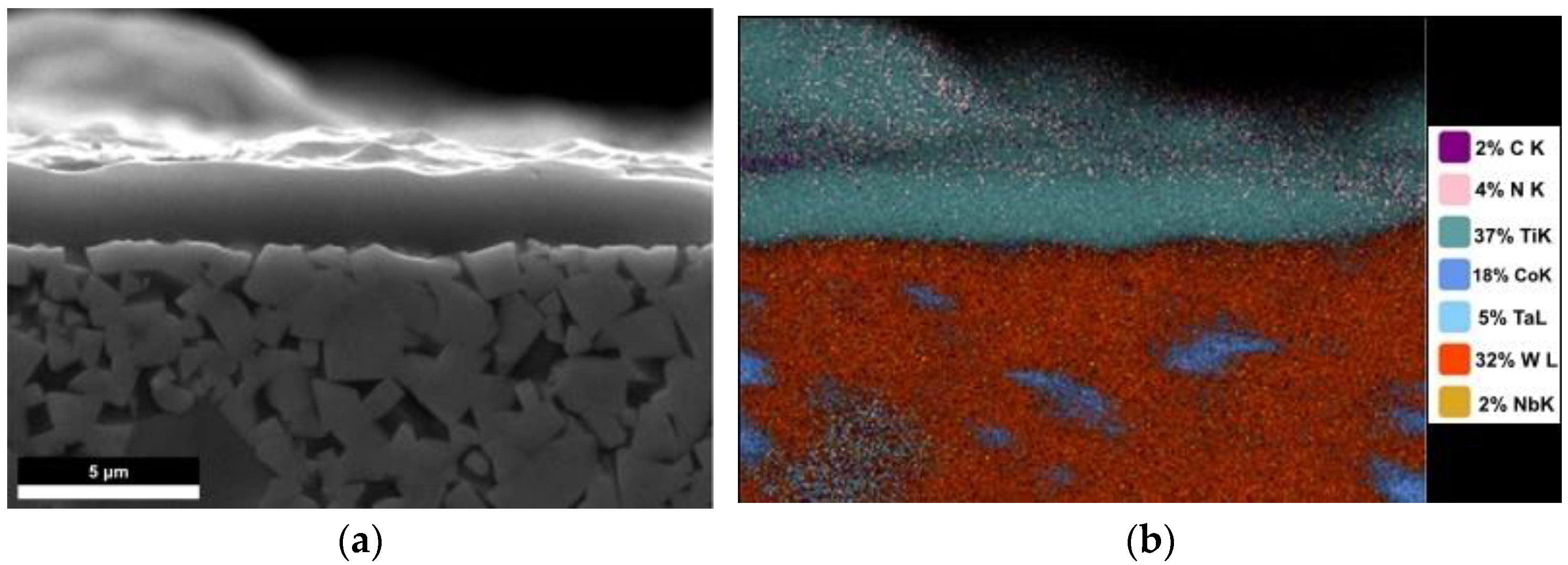
3.1. Scanning Electron Microscopy and Energy-Dispersive Spectrometry (SEM-EDS)

The SEM images (Figure 1 and Figure 2) of the cross sections through the TiN and TiAlN coatings show that the coating layers were continuous while the substrates were granulated. Figure 1b clearly shows the spreading of the Co throughout the substrate matrix, but no diffusion of Co into the coating was observed.
The composition of the TiN coating given in Table 1 is affected by the parasitic signals caused by the electron beam spreading onto the substrate, giving rise to the W, Co, and C incidence. If the W, Co, and C are disregarded, then the coating composition is quite stoichiometric (TiN). The elemental maps carried on the TiN–substrate interface do not highlight the interdiffusion of the Ti, N, W, and Co. Thus, the TiN coating adhesion to the substrate could not be attributed to an interdiffusion mechanism, but to mechanical and/or chemical ones.
The composition of the TiAlN coating, given in Table 2, presents the same artifacts as that of the TiN, but the atomic concentrations given in Table 2 support the stoichiometry of the (Ti, Al)N layer.
The elemental map of the TiAlN–substrate interface (Figure 2) does not highlight the interdiffusion of the Ti, N, Al, W, and Co. As for the TiN, the adhesion of the TiAlN coating to substrate cannot be related to an interdiffusion mechanism. The SEM images show smoother interfaces between the WC-Co and the coatings (TiN and TiAlN). Thus, the mechanical adherence could be generated by the penetration of the coating substance in the plasma state into the superficial crevices (pores) of the substrate.
The SEM observations reveal a quasi-uniform thickness of the coatings deposited by the CAE-PVD process while the EDS measurements prove that there is no elemental interdiffusion through the interface.

3.2. X-ray Diffraction (XRD)

The XRD pattern of the blank WC substrate, e.g., without grain growth inhibitors (TiC, TaC, and NbC) addition (Figure 3) shows only the peaks assigned to the WC phase (ICDD card No. 03-1096).
The XRD measurements carried on the MCT specimen provided quite similar diffractograms to that given in Figure 4, but showing the TiC lines (ICDD card No. 06-0614.).
The peaks of the TaC and NbC could not be clearly revealed by XRD data processing (stripping and deconvolution). The lack of the TaC and NbC peaks could be caused by at least three factors: low TaC and NbC concentrations; structural distortions; and dissolution during the sintering process.
The diffractograms of the TiN coating show the XRD lines ascribed to the WC substrate and tow lines that were assigned to the FCC TiN phase, i.e., (111) and (200), ICDD card No. 38-1420, as is shown in Figure 5.
The TiAlN coating provided the XRD lines ascribed to the WC of the substrate and two lines that were clearly assigned to the (TiAl)N phase, i.e., (111) and (200), ICDD card No. 71-5864, as is shown in Figure 6.
The XRD data show that the coatings were polycrystalline. Additionally, they have the same FCC structure type. The interplanar spacing (d) was used as a strain gauge for assessing the residual stresses into the coatings, based on the Equation given in [35,38]:
σ = E e = E d h k l d 0 h k l d 0 h k l
where E is Young’s modulus, dhkl is the measured interplanar with (hkl) Miller indices, and d0hkl is the strain-free interplanar spacing for the same family planes.
The stress levels (σ) were calculated using the values of the Young’s modulus posted in [39,40]. The values of the second-order stresses into TiN and (TiAl)N coatings are posted in Table 3.
The stress levels into the TiN and TiAlN coatings were quite low because the differences among the interplanar distances of the unstressed and stressed coatings were less than 1% of the d0hkl value. The TiN coating exhibited positive stresses meaning that the TiN coating suffered a shear contraction due to the substrate. On the contrary, TiAlN exhibited negative ones, i.e., it suffered shear extension.
The average crystalline size (D) of the TiN and (TiAl)N phases were estimated based on the Scherrer approach [41]:
D = k   λ β cos θ
where k = 0.9 is the Scherrer constant, λ is the wavelength of the radiation, β is the corrected FWHM expressed in radian, and θ is the Bragg angle of the peak.
An accurate estimation of the crystallite size is quite difficult due to the unknown distribution of the crystallite sizes and of their shapes. The crystallite sizes estimated for different (hkl) Miller indices are given in Table 4.
The average crystallite size of the blank WC substrate was about 128 nm while the average crystallite size of the WC substrate with grain growth inhibitors added was about 72 nm (Table 4). TiC, TaC, and NbC addition decreased the crystallite size of WC by 44%. The average TiN crystallite size was about 65 nm while that of the (TiAl)N was about 55 nm. The decrease in the (TiAl)N average crystallite size can be attributed to the substitution of the Ti atoms by the Al atoms in the TiN lattice.
The texture of the specimens was quantified based on the “texture coefficient” (Thkl), which is an adequate estimator for such a coating [42]:
T h k l = I h k l I 0 h k l 1 n n I h k l I 0 h k l
where I (hkl) is the measured relative intensity of the (hkl) peak, I0 (hkl) is the standard intensity assigned to the same (hkl) planes whose value is specified in the ICDD file, and n is the number of the peaks used to assess the Thkl value.
A Thkl value < 1 indicates a smaller fraction of crystallites that have the <hkl> directions normal to the coating surface, while a Thkl value > 1 indicates an abundance of such crystallites. The XRD patterns (Figure 5 and Figure 6) definitely show that the TiN and the TiAlN coatings were textured. The average T111 of the TiN coatings was about 1.52, which indicates significant <111> preferred orientations relative to the <200> direction. The average T200 of the TiAlN coating was about 1.55 which indicates significant <200> preferred orientations. The Thkl values of both coatings suggest that the texture mechanisms in the TiN coating differed from that in the TiAlN one, i.e., the TiN crystallites were oriented along the <111> direction while the (TiAl)N ones were oriented along the <200> direction.
The CAE-PVD deposition process is a hybrid one, consisting of three intricated processes, i.e., ion deposition, cluster deposition, and droplets [43,44,45]. Our XRD data indicate the preferred growth of the TiN and (TiAl)N crystallites. It can be explained through a cluster growth mechanism that favorizes selective accommodation of the clusters on specific Miller planes. The coating thicknesses (t) were estimated based on the attenuation of the substrate diffraction lines according to the de Beer–Lambert law [46]:
t = sin ( θ ) 2 μ l n I I 0
where θ is the Bragg angle, I is the diffracted integral intensity of a substrate peak covered with the coating, I0 is the same quantity corresponding to the uncovered substrate, and μ is the linear absorption coefficient of the material [47,48].
The integral intensity of the strongest diffraction line given by the uncoated substrate has been compared to that given by the coated ones. The average thickness of the TiN coating is tTiN = 4.3 μm while that of the TiAlN coating is tTiAlN = 3.6 μm. The estimated uncertainties for tTiN and tTiAlN are UTiN [95%] = 0.3 μm and UTiAlN [95%] = 0.3 μm, respectively.

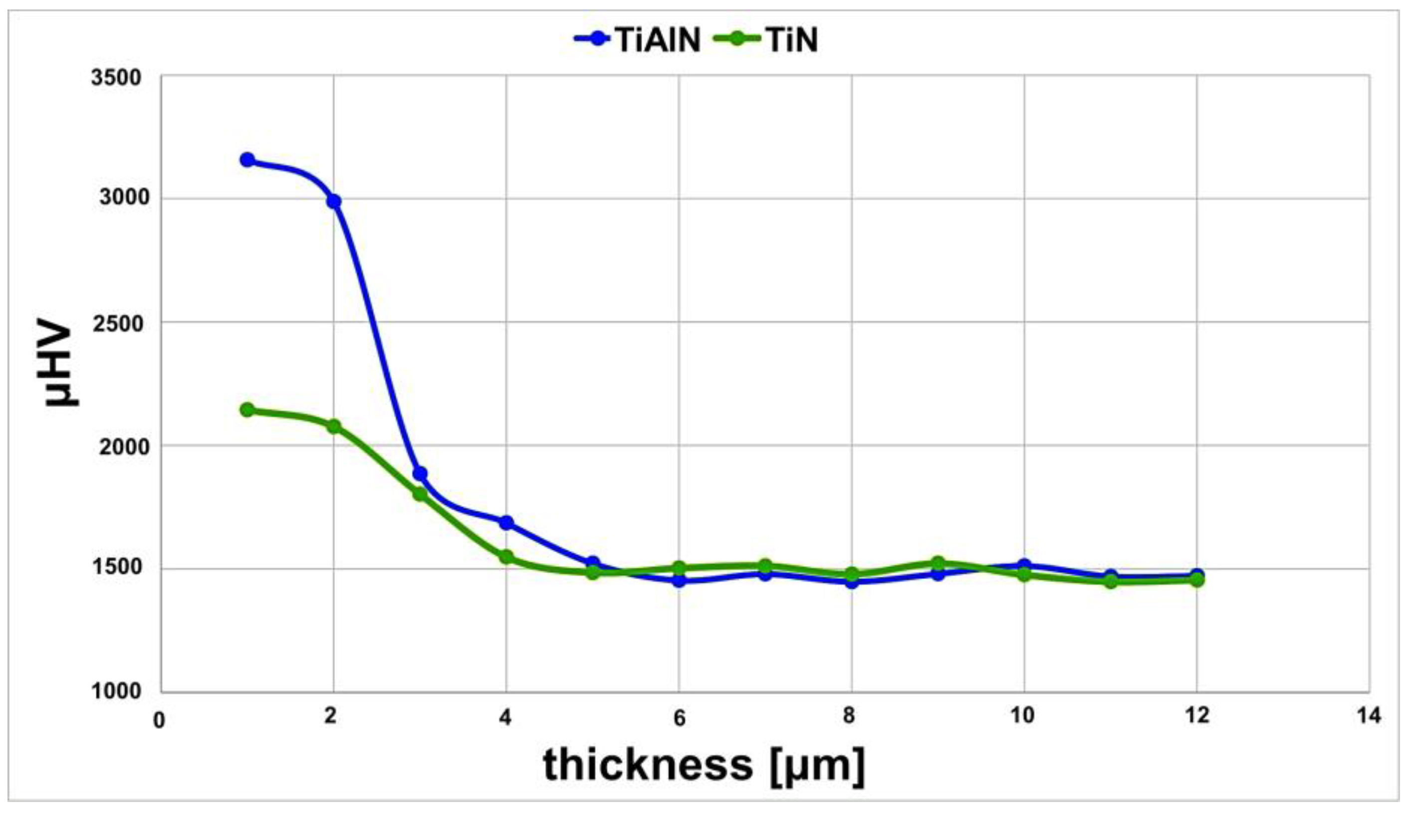
3.3. Microhardness Measurements

The Vickers microhardness of the uncoated tool (MCT) was estimated as 1485 µHV with an expanded uncertainty of 14 µHV corresponding to a 95% confidence level. The MCT-TN and MCT-TAN coatings had increased µHV values, i.e., 2174 ± 29 µHV (95%) in case of the TiN coating and 3187 ± 31 µHV (95%) in case of the TiAlN coating. The TiN coating showed a low µHV value compared with the one of the TiAlN coating.
The microhardness variations across the interface as a function of the distance from the top coated surface towards the substrates for the TiN and TiAlN systems are shown in Figure 7. The gradient of the microhardness distribution across the interface is caused by the vicinity of the softer substrate rather than by the decrease in the intrinsic hardness of the coating.
The higher microhardness of the TiAlN coating compared with that of the TiN one can be attributed to the dislocation effect and to the internal stress arising from the partial replacement of the Ti atoms by the Al atoms in the TiN lattice [49].

3.4. Atomic Force Microscopy

The coating-surface morphologies (Figure 8a,b) resembled that of orange peel, i.e., the coatings exhibited pits, pores, and black points (particles) of micron size.
Figure 8 points out that the roughness of the specimens was higher. These aspects are typical for the CAE-PVD deposition technique due to its high mass deposition rate. Accordingly, the higher roughness could be explained by a cluster growth mechanism; i.e., the TiN and TiAlN nucleate partially in highly dense ionic plasma and, subsequently, the clusters accommodate onto the specific crystalline plane.
Representative AFM images of the TiN and TiAlN coatings are presented in Figure 9a and Figure 9b, respectively. The AFM image of the TiAlN (Figure 9b) shows a smoother surface topography compared to the TiN one (Figure 9a).
The average values of the Ra and Rq parameters measured for the TiN and TiN coatings are given in Table 5.
Since there was no overlapping of the confidence intervals, the values of Ra and Rq posted in Table 5 reveal that the TiAlN coatings were smoother than that of the TiN. Noteworthy, the important role played by the U (95%) in a comparative study based on numerical values, such as in this case.
The literature information and other data support the hypothesis that a hard coating, whatever its nature (i.e., TiN vs. TiAlN), has better performance inasmuch as it consists of smaller crystallites, shows higher hardness, it is smoother, it is free of stress, and has an adequate thickness [27,50]. The values of the addressed measurands are summarized in Table 6.
The differences between the values of the same measurand obtained on TiN and TiAlN were tested using Welch’s t-test [51]. The TiN or the TiAlN receives a “+” mark if one has a better value. The cases in which the measurands’ values cannot be statistically discriminated are marked with “?”.
In this regard, the average crystallite sizes and the thicknesses of the TiN and TiAlN coatings cannot be statistically discriminated. The Ra, Rq, and µHV values of the coatings can be clearly discriminated and they are higher in the case of the TiAlN coating. On the other hand, the opposite sign of the σ remains to be explained based on further research. As can be observed in Table 6, all the “+” marks were assigned to the TiAlN coating; therefore, it can be considered superior to the TiN ones.

4. Conclusions

The values of the crystallite size, stress level, texture coefficient, thickness, roughness parameters, and microhardness showed that the TiAlN coating is more appropriate for the new WC-Co tool than the TiN one.
Noteworthily, the comparative study was conducted in the frame of the ISO 98-3, i.e., using expanded uncertainty with a 95% confidence level as a band-guard between compared values.
SEM-EDS showed that there was no elemental interdiffusion between the substrates and coatings (TiN and TiAlN) which disregards the interdiffusion adhesion mechanism of the coatings to substrates. Additionally, the SEM, XRD, and AFM results provide a thorough insight of the structural and morphological features of the TiN and TiAlN coatings, validating the XRD and AFM outcomes and supporting further research toward improving the performance of such coatings.
Although the values of σ and Thkl do not support the discrimination between the studied coatings, because they are of different types, these findings are important as they differentiate the TiN and TiAlN coatings.
The XRD measurements provided quite similar values for the D and t measurands.
The Ra, Rq, and µHV definitely support the superiority of the TiAlN coating compared with the TiN one.
Noteworthily, the superiority of the TiAlN coating does not disqualify the TiN as a hard coating for cutting tools, as the D and t values could not be discriminated. Additionally, the effects of the different preferred orientations and stresses on the functional properties of the studied coatings are unknown.
An explanation of the XRD data regarding the preferred orientation of the TiN and TiAlN crystallites needs further research to elucidate its intimate phenomenology, which leads to different preferred orientations of the crystallites.

Author Contributions

A.A.M. and I.P.: Conceptualization. R.N.T. and F.N.: Methodology. A.A.M.: software. M.I.P.: Validation. F.N.: Formal analysis. A.A.M. and R.N.T.: Investigations. E.H.: Resources, Data curation. I.P.: Writing—original draft preparation. I.P. and R.N.T.: writing—review and editing. I.P. and R.N.T.: Visualization. M.I.P.: Supervision. All authors have read and agreed to the published version of the manuscript.

Funding

This research received no external funding.

Institutional Review Board Statement

Not applicable.

Informed Consent Statement

Not applicable.

Data Availability Statement

Not applicable.

Acknowledgments

The authors acknowledge Emilia Ciovica (University of VALAHIA, Targoviste, Romania) for providing the tool samples.

Conflicts of Interest

The authors declare no conflict of interest.

References

  1. Andersson, J.M.; Vetter, J.; Müller, J.; Sjölén, J. Structural effects of energy input during growth of Ti1− xAlxN (0.55 ≤ x ≤ 0.66) coatings by cathodic arc evaporation. Surf. Coat. Technol. 2014, 240, 211–220. [Google Scholar] [CrossRef]
  2. Ahlgren, M.; Blomqvist, H. Influence of bias variation on residual stress and texture in TiAlN PVD coatings. Surf. Coat. Technol. 2005, 200, 157–160. [Google Scholar] [CrossRef]
  3. Hörling, A.; Hultman, L.; Odén, M.; Sjölén, J.; Karlsson, L. Mechanical properties and machining performance of Ti1− xAlxN-coated cutting tools. Surf. Coat. Technol. 2005, 191, 384–392. [Google Scholar] [CrossRef]
  4. Palomar, F.E.; Zambrano, P.C.; Gomez, M.I.; Colas, R.; Guerrero, M.P.; Castillo, A. Coatings made of tungsten carbide and tantalum carbide for machining tools. Vacuum 2010, 84, 1236–1239. [Google Scholar] [CrossRef]
  5. Lungu, M.V. An Insight into TiN, TiAlN and AlTiN Hard Coatings for Cutting Tools. Mat. Sci. Res. India 2020, 17, 87–89. [Google Scholar] [CrossRef]
  6. El Rayes, M.M.; Sherif, E.-S.M.; Abdo, H.S. Comparative Study into Microstructural and Mechanical Characterization of HVOF-WC-Based Coatings. Crystals 2022, 12, 969. [Google Scholar] [CrossRef]
  7. Yang, X.H.; Wang, K.F.; Zhang, G.H.; Chou, K.C. Fabrication and performances of WC-Co cemented carbide with a low cobalt content. Int. J. Appl. Ceram. Technol. 2021, 19, 1341–1353. [Google Scholar] [CrossRef]
  8. Duman, D.; Gökce, H.; Cimenoglu, H. Synthesis, microstructure, and mechanical properties of WC–TiC–Co ceramic composites. J. Eur. Ceram. Soc. 2012, 32, 1427–1433. [Google Scholar] [CrossRef]
  9. Kim, H.C.; Shon, I.J.; Munir, Z.A. Rapid sintering of ultra-fine WC–10 wt% Co by high-frequency induction heating. J. Mater. Sci. 2005, 40, 2849–2854. [Google Scholar] [CrossRef]
  10. Sampath Kumar, T.; Balasivanandha Prabu, S.; Manivasagam, G. Metallurgical Characteristics of TiAlN/AlCrN Coating Synthesized by the PVD Process on a Cutting Insert. J. Mater. Eng. Perform. 2014, 23, 2877–2884. [Google Scholar] [CrossRef]
  11. Hong, L.; Bian, G.; Hu, S.; Wang, L.; Dacosta, H. Tribological Properties of CrAlN and TiN Coatings Tested in Nano- and Micro-scale Laboratory Wear Tests. J. Mater. Eng. Perform. 2015, 24, 2670–2677. [Google Scholar] [CrossRef]
  12. Wei, Y.Q.; Li, C.W.; Gong, C.Z.; Tian, X.B.; Yang, S.Q. Microstructure and mechanical properties of TiN/TiAlN multilayer coatings deposited by arc ion plating with separate targets. Trans. Nonferrous Met. Soc. China 2011, 21, 1068–1073. [Google Scholar] [CrossRef]
  13. Zhao, Y.; Guo, C.; Yang, W.; Chen, Y.; Yu, B. TiN films deposition inside stainless-steel tubes using magnetic field-enhanced arc ion plating. Vacuum 2015, 112, 46–54. [Google Scholar] [CrossRef]
  14. Dobrzanski, L.A.; Zukowska, L.W.; Mikula, J.; Golombek, K.; Pakula, D.; Pancielejko, M. Structure and mechanical properties of gradient PVD coatings. J. Mater. Process. Technol. 2008, 201, 310–314. [Google Scholar] [CrossRef]
  15. Pang, X.; Zhang, L.; Yang, H.; Gao, K.; Volinsky, A.A. Residual Stress and Surface Energy of Sputtered TiN Films. J. Mater. Eng. Perform. 2015, 24, 1185–1191. [Google Scholar] [CrossRef] [Green Version]
  16. Aihua, L.; Jianxin, D.; Haibing, C.; Yangyang, C.; Jun, Z. Friction and wear properties of TiN, TiAlN, AlTiN and CrAlN PVD nitride coatings. Int. J. Refract. Met. Hard Mater. 2012, 31, 82–88. [Google Scholar] [CrossRef]
  17. Tomaszewski, Ł.; Gulbiński, W.; Urbanowicz, A.; Suszko, T.; Lewandowski, A.; Gulbiński, W. TiAlN based wear resistant coatings modified by molybdenum addition. Vacuum 2015, 121, 223–229. [Google Scholar] [CrossRef]
  18. Barshilia, H.C.; Yogesh, K.; Rajam, K.S. Deposition of TiAlN coatings using reactive bipolar-pulsed direct current unbalanced magnetron sputtering. Vacuum 2008, 83, 427–434. [Google Scholar] [CrossRef]
  19. Bengoa, L.N.; Tuckart, W.R.; Zabala, N.; Prieto, G.; Egli, W.A. Tin Coatings Electrodeposited from Sulfonic Acid-Based Electrolytes: Tribological Behavior. J. Mater. Eng. Perform. 2015, 24, 2274–2281. [Google Scholar] [CrossRef]
  20. Skoric, B.; Kakas, D.; Bibic, N.; Rakita, M. Microstructural studies of TiN coatings prepared by PVD and MAD. Surf. Sci. 2004, 566, 40–44. [Google Scholar] [CrossRef]
  21. Zhang, L.; Yang, H.; Pang, X.; Gao, K.; Tran, H.T.; Volinsky, A.A. TiN-Coating Effects on Stainless Steel Tribological Behavior Under Dry and Lubricated Conditions. J. Mater. Eng. Perform. 2014, 23, 1263–1269. [Google Scholar] [CrossRef] [Green Version]
  22. Vera, M.V.E.E.; Lewis, R.; Gallardo, E.A.; Laguna-Camacho, J.R. A study of the wear performance of TiN, CrN and WC/C coatings on different steel substrate. Wear 2011, 271, 2116–2124. [Google Scholar] [CrossRef]
  23. Vilhena, L.; Domingues, B.; Fernandes, C.; Senos, A.; Ramalho, A. Mechanical and Tribological Characterization of WC-Co andWC-AISI 304 Composites by a NewlyDeveloped Equipment. Materials 2022, 15, 1187. [Google Scholar] [CrossRef] [PubMed]
  24. Mikuła, J.; Pakuła, D.; Żukowska, L.; Gołombek, K.; Kříž, A. Wear Resistance of (Ti,Al)N Metallic Coatings for Extremal Working Conditions. Coatings 2021, 11, 157. [Google Scholar] [CrossRef]
  25. Ding, X.; Bui, C.T.; Zeng, X.T. Abrasive wear resistance of Ti1−xAlxN hard coatings deposited by a vacuum arc system with lateral rotating cathodes. Surf. Coat. Technol. 2008, 203, 680–684. [Google Scholar] [CrossRef]
  26. Subramanian, B.; Muraleedharan, C.V.; Ananthakumar, R.; Jayachandran, M. A comparative study of titanium nitride (TiN), titanium oxy nitride (TiON) and titanium aluminum nitride (TiAlN), as surface coatings for bio implants. Surf. Coat. Technol. 2011, 205, 5014–5020. [Google Scholar] [CrossRef]
  27. Danışman, S.; Odabaş, D.; Teber, M. The Effect of TiN, TiAlN, TiCN Thin Films Obtained by Reactive Magnetron Sputtering Method on the Wear Behavior of Ti6Al4V Alloy: A Comparative Study. Coatings 2022, 12, 1238. [Google Scholar] [CrossRef]
  28. He, C.L.; Zhang, J.L.; Wang, J.M.; Ma, G.F.; Zhao, D.L.; Cai, Q.K. Effect of structural defects on corrosion initiation of TiN nanocrystalline films. Appl. Surf. Sci. 2013, 276, 667–671. [Google Scholar] [CrossRef]
  29. Heydari, L.; Lietor, P.F.; Corpas-Iglesias, F.A.; Laguna, O.H. Ti(C,N) and WC-Based Cermets: A Review of ynthesis, Properties and Applications in Additive Manufacturing. Materials 2021, 14, 6786. [Google Scholar] [CrossRef] [PubMed]
  30. Huang, S.G.; Liu, R.L.; Li, L.; Van der Biest, O.; Vleugels, J. NbC as grain growth inhibitor and carbide in WC-Co hardmetals. Int. J. Refract. Met. Hard Mater. 2008, 26, 389–395. [Google Scholar] [CrossRef]
  31. Xiao, D.-H.; He, Y.-H.; Luo, W.-H.; Song, M. Effect of VC and NbC additions on microstructure and properties of ultrafine WC-10 Co cemented carbides. Trans. Nonferrous Met. Soc. China 2009, 19, 1520–1525. [Google Scholar] [CrossRef]
  32. Weidow, J.; Andrén, H.-O. Grain and phase boundary segregation in WC–Co with TiC, ZrC, NbC or TaC additions. Int. J. Refract. Met. Hard Mater. 2011, 29, 38–43. [Google Scholar] [CrossRef]
  33. Lee, H.R.; Kim, D.J.; Hwang, N.M.; Kim, D.-Y. Role of vanadium carbide additive during sintering of WC–Co: Mechanism of grain growth inhibition. J. Am. Ceram. Soc. 2003, 86, 152–154. [Google Scholar] [CrossRef]
  34. Naglič, I.; Zaky, A.; Leskovar, B.; Čekada, M.; Markoli, B. Characterization of different WC-Co cemented-carbide tools. Mater. Technol. 2022, 56, 423–428. [Google Scholar] [CrossRef]
  35. Matei, A.A.; Pencea, I.; Stanciu, S.G.; Hristu, R.; Antoniac, I.; Ciovica (Coman), E.; Sfat, C.E.; Stanciu, G.A. Structural characterization and adhesion appraisal of TiN and TiCN coatings deposited by CAE-PVD technique on a new carbide composite cutting tool. J. Adhes. Sci. Technol. 2015, 29, 2576–2589. [Google Scholar] [CrossRef]
  36. ISO/IEC 17025:2018; General Requirements for the Competence of Testing and Calibration Laboratories. IOS: Geneva, Switzerland, 2018.
  37. ISO/IEC 98-3:2008; Uncertainty of Measurement—Part 3: Guide to the Expression of Uncertainty in Measurement. IOS: Geneva, Switzerland, 2008.
  38. Şavklıyıldız, İ. In-Situ Strain Measurement on Al7075 Plate by Using High Energy Synchrotron Light Source. Eur. J. Eng. Sci. Technol. 2021, 23, 435–439. [Google Scholar] [CrossRef]
  39. Sivitski, A.; Gregor, A.; Saarna, M.; Kulu, P.; Sergejev, F. Application of the indentation method for cracking resistance evaluation of hard coatings on tool steels. Est. J. Eng. 2009, 15, 309–317. [Google Scholar] [CrossRef] [Green Version]
  40. Sampath Kumar, T.; Balasivanandha Prabu, S.; Manivasagam, G.; Padmanabhan, K.A. Comparison of TiAlN, AlCrN, and AlCrN/TiAlN coatings for cutting-tool applications. Int. J. Miner. Met. Mater. 2014, 21, 796–805. [Google Scholar] [CrossRef]
  41. Langford, J.I.; Wilson, A.J.C. Scherrer after sixty years: A survey and some new results in the determination of crystallite size. J. Appl. Crystallogr. 1978, 11, 102–113. [Google Scholar] [CrossRef]
  42. Abadias, G. Stress and preferred orientation in nitride-based PVD coatings. Surf. Coat. Technol. 2008, 202, 2223–2235. [Google Scholar] [CrossRef]
  43. Gudmundsson, J.T.; Anders, A.; von Keudell, A. Foundations of physical vapor deposition with plasma assistance. Plasma Sources Sci. Technol. 2022, 31, 083001. [Google Scholar] [CrossRef]
  44. Sebastiani, M.; Piccoli, M.; Bemporad, E. Effect of micro-droplets on the local residual stress field in CAE-PVD thin coatings. Surf. Coat. Technol. 2013, 2015, 407–412. [Google Scholar] [CrossRef]
  45. Ali, M.; Hamzah, E.; Qazi, I.A.; Toff, M.R.M. Growth Defects and Surface Roughness in TiN-Coated Tool Steel at Various N2 Gas Flow Rates Using Cathodic Arc PVD Technique. Mater. Sci. Forum 2010, 636–637, 965–970. [Google Scholar] [CrossRef]
  46. Hejdova, H.; Cermak, M. A new X-ray-diffraction method for thin-film thickness estimation. Phys. Status Solidi A 1982, 72, 95–98. [Google Scholar] [CrossRef]
  47. Rafaja, D.; Valvoda, V.; Perry, A.J.; Treglio, J.R. Depth profile of residual stress in metal-ion implanted TiN coatings. Surf. Coat. Technol. 1997, 92, 135–141. [Google Scholar] [CrossRef]
  48. Vlasveld, A.C.; Harris, S.G.; Doyle, E.D.; Lewis, D.B.; Munz, W.D. Characterisation and performance of partially filtered arc TiAlN coatings. Surf. Coat. Technol. 2002, 149, 217–223. [Google Scholar] [CrossRef]
  49. Chen, L.; Du, Y.; Wang, S.Q.; Li, J. A comparative research on physical and mechanical properties of (Ti, Al)N and (Cr, Al)N PVD coatings with high Al content. Int. J. Refract. Met. Hard Mater. 2007, 25, 400–404. [Google Scholar] [CrossRef]
  50. Long, Y.; Zeng, J.; Yu, D.; Wu, S. Microstructure of TiAlN and CrAlN coatings and cutting performance of coated silicon nitride inserts in cast iron turning. Ceram. Int. 2014, 40 Pt A, 9889–9894. [Google Scholar] [CrossRef]
  51. Welch, B.L. The generalization of “Student’s” problem when several different population variances are involved. Biometrika 1947, 34, 28–35. [Google Scholar] [CrossRef]
Figure 1. The SEM images of: (a) TiN–substrate interface; (b) TiN–substrate element overlay.
Crystals 13 00112 g001
Figure 2. The SEM images of: (a) TiAlN–substrate interface; (b) TiAlN–substrate element overlay. Note. The upper magenta layer in (b) assigned to C is an instrumental artefact.
Crystals 13 00112 g002
Figure 3. The representative XRD pattern of blank WC-Co substrate (cutting tool).
Crystals 13 00112 g003
Figure 4. The representative XRD patterns of the MCT specimen.
Crystals 13 00112 g004
Figure 5. The representative XRD patterns of the MCT-TN.
Crystals 13 00112 g005
Figure 6. The representative XRD patterns of the MCT-TAN specimen.
Crystals 13 00112 g006
Figure 7. Microhardness profiles across the TiN and TiAlN coatings and substrates.
Crystals 13 00112 g007
Figure 8. Representative optical micrographics: (a) TiN coating; (b) TiAlN coating.
Crystals 13 00112 g008
Figure 9. The AFM images: (a) the 3D topography of the TiN coating; (b) the 3D topography of the TiAlN coating.
Crystals 13 00112 g009
Table 1. The composition of the TiN coating.
ElementWeigh %Atomic %Net Int.Error %
N K31.4262.962149.196.54
Ti K59.9535.1332,998.041.16
Co K1.510.72459.336.41
W L6.551.00772.406.05
Table 2. The composition of the TiAlN coating.
ElementWeigh %Atomic %Net Int.Error %
C K6.3412.08209.5310.24
N K31.5351.531255.339.13
Al K23.7720.1712,748.565.99
Ti K31.6715.1419,859.471.43
Co K0.960.37364.916.13
W L5.740.71820.736.57
Table 3. The stress values, their measurement uncertainties, and supported data.
CoatingPhasehkldhkld0hklσ (GPa)U [95%] (GPa)
TiNTiN1112.4622.4492.20.2
2002.1232.1210.50.2
TiAlN(TiAl)N1112.4042.419−2.80.3
2002.0882.095−1.20.2
Table 4. The average crystallite sizes, their measurement uncertainties, and supported data.
SpecimenPhasehklD (nm)U [95%] (nm)
WC-CoWC0011285
WC-Co and inhibitorsWC001723
WC-Co and inhibitorsTiC200683
TiNTiN111663
200642
TiAlN(TiAl)N111563
200543
Table 5. The roughness average values of the TiN and TiAlN coatings and their measurement uncertainties.
Coating Ra (nm)URa [95%] (nm)Rq (nm)URq [95%] (nm)
TiN2461630915
TiAlN2091126812
Table 6. The summarized characteristics of the TiN and TiAlN coatings and the assigned marks: “+” for the better values and ”?” for indiscriminate values.
Coating Materialσ (GPa)D(nm)Thklt (μm)µHVRa (nm)Rq (nm)
TiN2.266T111
1.52
4.32174246309
TiAlN−2.855T200
1.55
3.63187209268
TiN????
TiAlN????+++
Disclaimer/Publisher’s Note: The statements, opinions and data contained in all publications are solely those of the individual author(s) and contributor(s) and not of MDPI and/or the editor(s). MDPI and/or the editor(s) disclaim responsibility for any injury to people or property resulting from any ideas, methods, instructions or products referred to in the content.

